EP1408571A2 - Behälterstruktur für Brennstoffzelle - Google Patents
Behälterstruktur für Brennstoffzelle Download PDFInfo
- Publication number
- EP1408571A2 EP1408571A2 EP03022847A EP03022847A EP1408571A2 EP 1408571 A2 EP1408571 A2 EP 1408571A2 EP 03022847 A EP03022847 A EP 03022847A EP 03022847 A EP03022847 A EP 03022847A EP 1408571 A2 EP1408571 A2 EP 1408571A2
- Authority
- EP
- European Patent Office
- Prior art keywords
- fuel cell
- container
- exhaust
- pipe
- compressed air
- Prior art date
- Legal status (The legal status is an assumption and is not a legal conclusion. Google has not performed a legal analysis and makes no representation as to the accuracy of the status listed.)
- Withdrawn
Links
- 239000000446 fuel Substances 0.000 title claims abstract description 146
- 238000007599 discharging Methods 0.000 claims abstract description 7
- 239000001257 hydrogen Substances 0.000 description 33
- 229910052739 hydrogen Inorganic materials 0.000 description 33
- UFHFLCQGNIYNRP-UHFFFAOYSA-N Hydrogen Chemical compound [H][H] UFHFLCQGNIYNRP-UHFFFAOYSA-N 0.000 description 32
- 239000007789 gas Substances 0.000 description 17
- 239000002737 fuel gas Substances 0.000 description 10
- 239000000428 dust Substances 0.000 description 9
- 239000012466 permeate Substances 0.000 description 4
- XLYOFNOQVPJJNP-UHFFFAOYSA-N water Substances O XLYOFNOQVPJJNP-UHFFFAOYSA-N 0.000 description 4
- 238000009423 ventilation Methods 0.000 description 3
- 230000000694 effects Effects 0.000 description 2
- 230000001590 oxidative effect Effects 0.000 description 2
- 238000005516 engineering process Methods 0.000 description 1
- 150000002431 hydrogen Chemical class 0.000 description 1
- 238000000034 method Methods 0.000 description 1
- 239000005518 polymer electrolyte Substances 0.000 description 1
- 239000007787 solid Substances 0.000 description 1
Images



Classifications
-
- H—ELECTRICITY
- H01—ELECTRIC ELEMENTS
- H01M—PROCESSES OR MEANS, e.g. BATTERIES, FOR THE DIRECT CONVERSION OF CHEMICAL ENERGY INTO ELECTRICAL ENERGY
- H01M8/00—Fuel cells; Manufacture thereof
- H01M8/24—Grouping of fuel cells, e.g. stacking of fuel cells
- H01M8/2465—Details of groupings of fuel cells
- H01M8/247—Arrangements for tightening a stack, for accommodation of a stack in a tank or for assembling different tanks
- H01M8/2475—Enclosures, casings or containers of fuel cell stacks
-
- H—ELECTRICITY
- H01—ELECTRIC ELEMENTS
- H01M—PROCESSES OR MEANS, e.g. BATTERIES, FOR THE DIRECT CONVERSION OF CHEMICAL ENERGY INTO ELECTRICAL ENERGY
- H01M8/00—Fuel cells; Manufacture thereof
- H01M8/04—Auxiliary arrangements, e.g. for control of pressure or for circulation of fluids
- H01M8/04082—Arrangements for control of reactant parameters, e.g. pressure or concentration
- H01M8/04089—Arrangements for control of reactant parameters, e.g. pressure or concentration of gaseous reactants
- H01M8/04104—Regulation of differential pressures
-
- H—ELECTRICITY
- H01—ELECTRIC ELEMENTS
- H01M—PROCESSES OR MEANS, e.g. BATTERIES, FOR THE DIRECT CONVERSION OF CHEMICAL ENERGY INTO ELECTRICAL ENERGY
- H01M2250/00—Fuel cells for particular applications; Specific features of fuel cell system
- H01M2250/20—Fuel cells in motive systems, e.g. vehicle, ship, plane
-
- Y—GENERAL TAGGING OF NEW TECHNOLOGICAL DEVELOPMENTS; GENERAL TAGGING OF CROSS-SECTIONAL TECHNOLOGIES SPANNING OVER SEVERAL SECTIONS OF THE IPC; TECHNICAL SUBJECTS COVERED BY FORMER USPC CROSS-REFERENCE ART COLLECTIONS [XRACs] AND DIGESTS
- Y02—TECHNOLOGIES OR APPLICATIONS FOR MITIGATION OR ADAPTATION AGAINST CLIMATE CHANGE
- Y02E—REDUCTION OF GREENHOUSE GAS [GHG] EMISSIONS, RELATED TO ENERGY GENERATION, TRANSMISSION OR DISTRIBUTION
- Y02E60/00—Enabling technologies; Technologies with a potential or indirect contribution to GHG emissions mitigation
- Y02E60/30—Hydrogen technology
- Y02E60/50—Fuel cells
-
- Y—GENERAL TAGGING OF NEW TECHNOLOGICAL DEVELOPMENTS; GENERAL TAGGING OF CROSS-SECTIONAL TECHNOLOGIES SPANNING OVER SEVERAL SECTIONS OF THE IPC; TECHNICAL SUBJECTS COVERED BY FORMER USPC CROSS-REFERENCE ART COLLECTIONS [XRACs] AND DIGESTS
- Y02—TECHNOLOGIES OR APPLICATIONS FOR MITIGATION OR ADAPTATION AGAINST CLIMATE CHANGE
- Y02T—CLIMATE CHANGE MITIGATION TECHNOLOGIES RELATED TO TRANSPORTATION
- Y02T90/00—Enabling technologies or technologies with a potential or indirect contribution to GHG emissions mitigation
- Y02T90/40—Application of hydrogen technology to transportation, e.g. using fuel cells
Definitions
- the present invention relates to a container structure housing a fuel cell of a fuel cell vehicle.
- a ventilation port is directly attached onto a container which houses a fuel cell, and outside air is taken therefrom to ventilate the inside of the container.
- the number of revolutions of a ventilation fan or opening/closing of an open valve is controlled in response to the concentration of hydrogen permeating a fuel cell stack, thus exhausting permeation hydrogen to the air.
- dirt such as dust, humidity and the like, which enter the fuel cell container from the outside while the outside air is being taken in or the permeation hydrogen is being exhausted to the air.
- the present invention was made in consideration of the above-described problems. It is an object of the present invention to provide a container structure for a fuel cell where there is a small possibility of entry of dirt such as dust, humidity and the like from the outside.
- the first aspect of the present invention provides a container structure for a fuel cell, comprising: a fuel cell container; a separate plate having a plurality of orifices; an exhaust pipe discharging gas in the fuel cell container; and a compressed air pipe sending a compressed air into the fuel cell container, wherein the inside of the fuel cell container is divided into an exhaust manifold unit and a cell housing unit housing the fuel cell by the separate plate, the exhaust pipe is attached to connect an exhaust port provided on the exhaust manifold unit and an exhaust outlet provided on a surface of a vehicle, and an air pressure in the exhaust manifold unit is set at an atmospheric pressure, and the compressed air pipe is attached onto the cell housing unit, and an air pressure in the cell housing unit is set equal to or smaller than a fuel cell gas pressure and equal to or larger than the atmospheric pressure.
- the second aspect of the present invention provides a container structure for a fuel cell, comprising: a fuel cell container; a separate plate having a plurality of orifices; and an exhaust pipe discharging gas in the fuel cell container, wherein the inside of the fuel cell container is divided into an exhaust manifold unit and a cell housing unit housing the fuel cell by the separate plate, the exhaust pipe is attached to connect an exhaust port provided on the exhaust manifold unit and an exhaust outlet provided on a surface of a vehicle, and an exhaust fan is provided in any one of the insides of the exhaust pipe and the exhaust manifold unit.
- the third aspect of the present invention provides a container structure for a fuel cell, comprising: a fuel cell container; an exhaust pipe discharging gas in the fuel cell container; a pipe making the fuel cell container and the exhaust pipe communicate with each other through an orifice; and a compressed air pipe sending a compressed air into the fuel cell container, wherein the orifice and the pipe are provided above the fuel cell container, an air pressure in the pipe is set at an atmospheric pressure by connecting the pipe to the exhaust pipe connected to an exhaust outlet provided on a surface of a vehicle, and the compressed air pipe is attached onto the fuel cell container, and an air pressure in the fuel cell container is set equal to or smaller than a fuel cell gas pressure and equal to or larger than the atmospheric pressure.
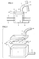
- FIGs. 1 to 9 A container structure for a fuel cell according to the present invention, in which a fuel cell 1 is housed in a container and mounted on a vehicle, will be described by use of FIGs. 1 to 9.
- the first embodiment includes the fuel cell 1, the fuel gas pipe 2 , the air pipe 3 , the exhaust pipe 7 , the compressed air pipe 8, and the fuel cell container 12.
- the fuel cell 1 As the fuel cell 1, a polymer electrolyte fuel cell (PEFC), a solid oxide fuel cell (SOFC) and the like can be utilized, whereas no particular limitations are imposed thereon.
- the fuel gas pipe 2 and the air pipe 3 are attached to the fuel cell 1, and supply fuel gas (hydrogen and the like) and oxidizing gas (air and the like) to the fuel cell 1.
- the fuel cell container 12 includes the exhaust manifold unit 5 as an upper lid portion and the cell housing unit 4 as a container portion.
- the separate plate 9 is sandwiched and fixed between the exhaust manifold unit 5 and the cell housing unit 4 in the inside of the fuel cell container 12.
- the orifices 6 are provided at all of the four corners and the center on the separate plate 9. Moreover, as shown in FIG. 9, with regard to the diameters of the orifices 6 provided in the separate plate 9, orifices 6 close to the exhaust port 13 are set small in diameter, and orifices 6 distant therefrom are set large in diameter.
- the fuel cell 1 into which the fuel gas pipe 2 and the air pipe 3 are attached are housed in the cell housing unit 4. Moreover, the compressed air pipe 8 is attached onto the corner of the side face of the cell housing unit 4.
- the exhaust pipe 7 extended from the exhaust port 13 to the vehicle side face 15 is attached onto the upper portion of the exhaust manifold unit 5. This exhaust pipe 7 is bent on the way from the exhaust port 13 to the vehicle side face 15.
- air compressed by a compressor for supply to the fuel cell 1 is divided and sent to the cell housing unit 4 from the compressed air pipe 8.
- air passing through an air filter (not shown) attached in the vicinity of the compressor is sent. Accordingly, dirt such as dust in the compressed air is removed.
- the air pressure in the cell housing unit 4 is set equal to or smaller than the fuel cell gas pressure and equal to or larger than the atmospheric pressure by the compressed air sent from the compressed air pipe 8. Therefore, an air pressure difference occurs between the cell housing unit 4 and the exhaust manifold unit 5, which is at the atmospheric pressure.
- the fuel cell gas pressure represents pressures of the fuel gas and oxidizing gas in the fuel cell stack.
- the permeation hydrogen flows into the exhaust manifold unit 5 through the orifices 6 while accelerating a flow velocity thereof by the air pressure difference. Then, the hydrogen is gathered together at the exhaust pipe 7 attached onto the exhaust port 13, and then discharged to the outside of the vehicle from the exhaust outlet 14 located on the vehicle side face 15.
- a structure is configured, in which the permeation hydrogen in the fuel cell container 12 is gathered together by the exhaust pipe 7 while accelerating the flow velocity by the air pressure difference, and then exhausted to the outside of the vehicle. Therefore, it is difficult for dirt such as dust to enter the fuel cell container.
- a structure is configured, in which the exhaust outlet 14 of the exhaust pipe 7 is located on the vehicle side face 15 without providing the exhaust outlet 14 directly to the fuel cell container 12. Therefore, dirt, water and the like can be prevented from adhered onto the fuel cell stack.
- a structure is configured, in which the hydrogen is gathered together by the exhaust pipe 7 and exhausted to the outside of the vehicle. Accordingly, the hydrogen can be exhausted to the outside of the vehicle no matter how the fuel cell container 12 is inclined.
- a ventilation port is provided directly to the container, and the hydrogen is exhausted therefrom. Consequently, in some cases, the hydrogen has remained in a dent in the inside of the vehicle, for example, on the back surface of a car hood.
- the container structure of the present invention is a structure in which the hydrogen is gathered together at one spot for exhausting and exhausted to the outside of the vehicle, and therefore, the hydrogen does not remain in the dent and the like in the inside of the vehicle.
- a permeation hydrogen sensor can be disposed easily in the fuel cell container 12.
- a structure is configured, in which a difference between the gas pressure in the fuel cell 1 and the air pressure outside the fuel cell 1 is reduced. Consequently, the permeation amount of the gas in the fuel cell 1 can be controlled.
- the exhaust manifold unit 5 is constructed so as not to be high, and to be narrow when compared with the cell housing unit 4. Hence, the exhaust manifold unit 5 does not lose the flow velocity accelerated by the air pressure difference. Specifically, if the space of the exhaust manifold unit 5 is wide, the permeation hydrogen that has been accelerated is diffused therein and decelerated. Consequently, the hydrogen is not exhausted to the outside of the vehicle efficiently. However, because the container structure of the present invention has the exhaust manifold unit 5, which is narrow, the permeation hydrogen can be exhausted securely, and further, the fuel cell container 12 can be space-saving.
- the separate plate 9 can be installed easily because the separate plate 9 is just sandwiched between the upper lid portion and container portion of the fuel cell container 12.
- orifices 6 close to the exhaust port 13 are set small in diameter, and orifices 6 distant therefrom are set large in diameter.
- the flow amount of gas exhausted from the large diameter orifices 6 becomes larger than the flow amount of gas exhausted from the small diameter orifices 6.
- the hydrogen remaining in the exhaust manifold unit 5 can be exhausted efficiently.
- a filter may be provided on the exhaust outlet 14 for the purpose of preventing the entry of dust and the like.
- FIGs. 3, 4 and 9 A configuration of a second embodiment will be described by use of FIGs. 3, 4 and 9. Note that, in the drawings, the same reference numerals will be given to portions similar to those of the first embodiment in the configuration of the container structure for the fuel cell of this embodiment, and repeated description will be omitted.
- the second embodiment includes the fuel cell 1, the fuel gas pipe 2, the air pipe 3, the exhaust pipe 7, the separate plate 9, the exhaust fan 10, and the fuel cell container 22. Further, the orifices 6 are provided in the separate plate 9. In this embodiment, the compressed air pipe 8 is not provided, but the exhaust fan 10 is provided in the vicinity of the exhaust port 13 of the exhaust pipe 7.
- a structure is configured, in which the permeation hydrogen in the fuel cell container 22 is gathered together by the exhaust pipe 7 while accelerating the flow velocity by the air pressure difference, and then exhausted to the outside of the vehicle. Therefore, it is difficult for dirt such as dust to enter the fuel cell container.
- a structure is configured, in which the exhaust outlet 14 of the exhaust pipe 7 is located on the vehicle side face 15 without providing the exhaust outlet 14 directly to the fuel cell container 22. Therefore, dirt, water and the like can be prevented from adhering onto the fuel cell stack.
- the exhaust fan 10 when the exhaust fan 10 is provided in the exhaust pipe 7, the gas sucked through the orifices 6 is gathered, thus making it possible to miniaturize the exhaust fan 10. Furthermore, because the exhaust fan 10 attached into the exhaust pipe 7 is miniaturized, it is made possible to enhance the degree of freedom in the attachment position of the exhaust fan 10 into the exhaust pipe 7.
- the attachment position of the exhaust fan is a mere example, and for example, even if the exhaust fan is attached into the exhaust manifold unit 5, a similar effect can be obtained.
- FIGs. 5 , 6 and 9 a configuration of a third embodiment will be described by use of FIGs. 5 , 6 and 9. Note that, in the drawings, the same reference numerals will be given to portions similar to those of the first embodiment in the configuration of the cell container for the fuel cell of this embodiment, and repeated description will be omitted.
- the third embodiment includes the fuel cell 1, the fuel gas pipe 2, the air pipe 3, the exhaust pipe 7, the compressed air pipe 8, the pipe 11, and the fuel cell container 32.
- the fuel cell 1 into which the fuel gas pipe 2 and the air pipe 3 are attached is housed in the cell housing unit 4 of the fuel cell container 32.
- the compressed air pipe 8 is attached onto the corner of the side face of the cell housing unit 4.
- the pipes 11 are provided as exhaust manifolds above the cell housing unit 4.
- Three pieces of the pipes 11 are arranged from one vertex of the upper surface of the fuel cell container 32 toward the three remaining vertexes.
- Each of the pipes 11 and the fuel cell container 32 are connected to each other by each of the orifices 6 attached on the four corners on the upper surface of the fuel cell container 32. Then, a point where the respective pipes 11 intersect is attached to the exhaust pipe 7 that is extended to the vehicle side face 15 and bent on the way.
- a structure is configured, in which the permeation hydrogen in the fuel cell container 32 is gathered together by the exhaust pipe 7 while accelerating the flow velocity by the air pressure difference, and then exhausted to the outside of the vehicle. Therefore, it is difficult for dirt such as dust to enter the fuel cell container.
- a structure is configured, in which the exhaust outlet 14 of the exhaust pipe 7 is located on the vehicle side face 15 without providing the exhaust outlet 14 directly to the fuel cell container 32. Therefore, dirt, water and the like can be prevented from adhering onto the fuel cell stack.
- the separate plate 9 can be eliminated, and in addition, by adjusting the diameters of the pipes 11, the flow velocity of the gas can be controlled, and further, the flow amount thereof can be restricted. Hence, the exhaust flow amount of the compressed air can be reduced more than in the first embodiment.
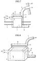
- FIGs. 7 and 8 a configuration of a fourth embodiment will be described by use of FIGs. 7 and 8. Note that, in the drawings, the same reference numerals will be given to portions similar to those of the first embodiment in the configuration of the fuel cell container of this embodiment, and repeated description will be omitted.
- the fourth embodiment includes the fuel cell 1, the fuel gas pipe 2, the air pipe 3, the exhaust pipe 7, the compressed air pipe 8, the separate plate 19, the pipe 11, and the fuel cell container 42.
- the fuel cell container 42 as a cuboid is composed of a hexagonal columnar space (cell housing unit 24) and two triangular columnar spaces (exhaust manifold units 25), in which the exhaust manifold units 25 are provided on the corners of the fuel cell container 24.
- the separate plates 19 are sandwiched and fixed between the cell housing unit 24 and the exhaust manifold units 25, in which the orifices 6 are provided.
- the fuel cell 1 into which the fuel gas pipe 2 and the air pipe 3 are attached is disposed in the cell housing unit 24 of the fuel cell container 42.
- the compressed air pipe 8 is attached onto the corner of the side face of the cell housing unit 24.
- the pipe 11 is located above the exhaust manifold units 25, connected thereto, respectively, and connects these two exhaust manifold units 25 to each other. This pipe 11 is attached to the exhaust pipe 7 that is extended to the vehicle side face 15 and bent on the way.
- a structure is configured, in which the permeation hydrogen in the fuel cell container 42 is gathered together by the exhaust pipe 7 while accelerating the flow velocity by the air pressure difference, and then exhausted to the outside of the vehicle. Therefore, it is difficult for dirt such as dust to enter the fuel cell container.
- a structure is configured, in which the exhaust outlet 14 of the exhaust pipe 7 is located on the vehicle side face 15 without providing the exhaust outlet 14 directly to the fuel cell container 42. Therefore, dirt, water and the like can be prevented from being adhered onto the fuel cell stack.
- a structure is configured, in which the narrow exhaust manifold units 25 that do not lose the flow velocity accelerated by the air pressure difference are added. Therefore, the fuel cell container 42 can be space-saving.
- the number and diameter of the orifices attached onto the separate plate can be set in accordance with the size and shape of the fuel cell container.
- the number and diameter of the orifices and the number and attachment method of the pipes can be set according to needs.
- the compressed air pipe is eliminated, and the exhaust fan is attached, thus making it possible to obtain a similar effect.
- the hydrogen can be exhausted more efficiently.
Landscapes
- Life Sciences & Earth Sciences (AREA)
- Engineering & Computer Science (AREA)
- Manufacturing & Machinery (AREA)
- Sustainable Development (AREA)
- Sustainable Energy (AREA)
- Chemical & Material Sciences (AREA)
- Chemical Kinetics & Catalysis (AREA)
- Electrochemistry (AREA)
- General Chemical & Material Sciences (AREA)
- Fuel Cell (AREA)
Applications Claiming Priority (2)
| Application Number | Priority Date | Filing Date | Title |
|---|---|---|---|
| JP2002296315 | 2002-10-09 | ||
| JP2002296315A JP2004134181A (ja) | 2002-10-09 | 2002-10-09 | 燃料電池容器構造 |
Publications (2)
| Publication Number | Publication Date |
|---|---|
| EP1408571A2 true EP1408571A2 (de) | 2004-04-14 |
| EP1408571A3 EP1408571A3 (de) | 2005-09-21 |
Family
ID=32025540
Family Applications (1)
| Application Number | Title | Priority Date | Filing Date |
|---|---|---|---|
| EP03022847A Withdrawn EP1408571A3 (de) | 2002-10-09 | 2003-10-08 | Behälterstruktur für Brennstoffzelle |
Country Status (3)
| Country | Link |
|---|---|
| US (1) | US20040072059A1 (de) |
| EP (1) | EP1408571A3 (de) |
| JP (1) | JP2004134181A (de) |
Cited By (4)
| Publication number | Priority date | Publication date | Assignee | Title |
|---|---|---|---|---|
| FR2896091A1 (fr) * | 2006-01-09 | 2007-07-13 | Peugeot Citroen Automobiles Sa | Pile a combustible et vehicule associe. |
| WO2008086923A1 (de) * | 2007-01-17 | 2008-07-24 | Robert Bosch Gmbh | Vorrichtung mit wenigstens einer elektrochemischen zelle in einem druckbeaufschlagten gehäuse und verfahren zum betreiben einer solchen vorrichtung |
| EP3086395A4 (de) * | 2013-12-18 | 2016-10-26 | Panasonic Ip Man Co Ltd | Stromerzeugungssystem |
| EP3136493A1 (de) * | 2015-08-27 | 2017-03-01 | Honda Motor Co., Ltd. | Brennstoffzellenfahrzeug |
Families Citing this family (15)
| Publication number | Priority date | Publication date | Assignee | Title |
|---|---|---|---|---|
| JP4839581B2 (ja) | 2004-06-18 | 2011-12-21 | 日産自動車株式会社 | 燃料電池のケース構造 |
| DE102004034870B4 (de) * | 2004-07-19 | 2007-08-09 | Liebherr-Aerospace Lindenberg Gmbh | System zur Wassergewinnung aus einem Abgasstrom einer Brennstoffzelle eines Luftfahrzeuges und Verwendung des Systems in einem Luftfahrzeug |
| FR2876499B1 (fr) * | 2004-10-11 | 2006-12-15 | Renault Sas | Agencement de conduites d'alimentation et/ou d'evacuation de fluides pour pile a combustible |
| JP5182540B2 (ja) * | 2004-12-07 | 2013-04-17 | トヨタ自動車株式会社 | 燃料電池用ケース |
| JP4555169B2 (ja) | 2005-06-24 | 2010-09-29 | 本田技研工業株式会社 | 燃料電池及び燃料電池スタック |
| DK2766947T3 (en) | 2011-10-14 | 2016-09-12 | Haldor Topsoe As | stack Unit |
| GB2499417A (en) | 2012-02-15 | 2013-08-21 | Intelligent Energy Ltd | A fuel cell assembly |
| JP6553371B2 (ja) * | 2014-03-20 | 2019-07-31 | 本田技研工業株式会社 | 燃料電池車両 |
| US9559379B2 (en) * | 2015-03-19 | 2017-01-31 | Delphi Technologies, Inc. | Heater |
| JP2018017648A (ja) * | 2016-07-29 | 2018-02-01 | 日産自動車株式会社 | ガス検知装置 |
| JP6674403B2 (ja) * | 2017-03-13 | 2020-04-01 | 本田技研工業株式会社 | 燃料電池搭載車輌 |
| CN110323472B (zh) * | 2018-03-30 | 2023-01-17 | 本田技研工业株式会社 | 燃料电池车辆及燃料电池用燃料气体检测装置 |
| JP7064924B2 (ja) * | 2018-03-30 | 2022-05-11 | 本田技研工業株式会社 | 燃料電池車両 |
| JP7264029B2 (ja) * | 2019-12-06 | 2023-04-25 | トヨタ自動車株式会社 | 燃料電池の冷却システム |
| CN115295826B (zh) * | 2022-07-25 | 2023-04-18 | 上海杰宁新能源科技发展有限公司 | 一种燃料电池控制方法、系统、存储介质及智能终端 |
Family Cites Families (9)
| Publication number | Priority date | Publication date | Assignee | Title |
|---|---|---|---|---|
| US4578324A (en) * | 1984-10-05 | 1986-03-25 | Ford Aerospace & Communications Corporation | Active cooling system for electrochemical cells |
| JPH0665063B2 (ja) * | 1986-05-06 | 1994-08-22 | 三洋電機株式会社 | 燃料電池の収納容器 |
| US4895774A (en) * | 1988-02-17 | 1990-01-23 | Kabushiki Kaisha Toshiba | Molten carbonate fuel cell |
| JPH01286260A (ja) * | 1988-05-13 | 1989-11-17 | Fuji Electric Co Ltd | 燃料電池の保護装置 |
| JP3549281B2 (ja) * | 1995-04-21 | 2004-08-04 | 東京瓦斯株式会社 | 燃料電池発電装置の排気ガス放出方法およびその装置 |
| US5980726A (en) * | 1998-05-05 | 1999-11-09 | Proton Energy Systems | Hydrogen electrochemical system environment |
| JP3686773B2 (ja) * | 1999-03-17 | 2005-08-24 | 京セラ株式会社 | 固体電解質型燃料電池 |
| US6605378B2 (en) * | 2000-04-06 | 2003-08-12 | Utc Fuel Cells, Llc | Functional integration of multiple components for a fuel cell power plant |
| JP4470346B2 (ja) * | 2001-01-18 | 2010-06-02 | トヨタ自動車株式会社 | 車載用燃料電池システムおよび水素オフガス排出方法 |
-
2002
- 2002-10-09 JP JP2002296315A patent/JP2004134181A/ja active Pending
-
2003
- 2003-09-12 US US10/660,531 patent/US20040072059A1/en not_active Abandoned
- 2003-10-08 EP EP03022847A patent/EP1408571A3/de not_active Withdrawn
Cited By (5)
| Publication number | Priority date | Publication date | Assignee | Title |
|---|---|---|---|---|
| FR2896091A1 (fr) * | 2006-01-09 | 2007-07-13 | Peugeot Citroen Automobiles Sa | Pile a combustible et vehicule associe. |
| WO2008086923A1 (de) * | 2007-01-17 | 2008-07-24 | Robert Bosch Gmbh | Vorrichtung mit wenigstens einer elektrochemischen zelle in einem druckbeaufschlagten gehäuse und verfahren zum betreiben einer solchen vorrichtung |
| EP3086395A4 (de) * | 2013-12-18 | 2016-10-26 | Panasonic Ip Man Co Ltd | Stromerzeugungssystem |
| EP3136493A1 (de) * | 2015-08-27 | 2017-03-01 | Honda Motor Co., Ltd. | Brennstoffzellenfahrzeug |
| US9701192B2 (en) | 2015-08-27 | 2017-07-11 | Honda Motor Co., Ltd. | Fuel cell vehicle |
Also Published As
| Publication number | Publication date |
|---|---|
| EP1408571A3 (de) | 2005-09-21 |
| JP2004134181A (ja) | 2004-04-30 |
| US20040072059A1 (en) | 2004-04-15 |
Similar Documents
| Publication | Publication Date | Title |
|---|---|---|
| US20040072059A1 (en) | Container structure for fuel cell | |
| US20250279447A1 (en) | Membrane humidifier for fuel cell | |
| US10854907B2 (en) | Fuel cell system | |
| US20180369736A1 (en) | Air filter arrangement; assembly; and, methods | |
| WO2020134054A1 (zh) | 动力电池包及车辆 | |
| CN110190211A (zh) | 电池托盘、动力电池包及车辆 | |
| CA2197433A1 (en) | Internal manifold assembly for an eletrochemical fuel cell stack array | |
| JP6232033B2 (ja) | 燃料電池スタック | |
| KR20100002303A (ko) | 가습기 및 연료전지시스템 | |
| CN108569126B (zh) | 燃料电池搭载车辆 | |
| US8968944B2 (en) | Humidifier device for humidifying a fluid in a fuel cell system | |
| US6805988B2 (en) | Humidifying apparatus for fuel cell | |
| CN107026278A (zh) | 车载用燃料电池堆 | |
| US6546954B2 (en) | Flow control valve | |
| US12347898B2 (en) | Membrane humidifier | |
| WO2002061868A1 (en) | Vacuum oxidant pem fuel cell | |
| US6582843B1 (en) | Fuel cell system | |
| CN219116699U (zh) | 一种多膜片吸附头 | |
| EP4328502A1 (de) | Luftbehandlungsvorrichtung | |
| EP4254570A1 (de) | Befeuchter für eine brennstoffzelle | |
| KR20240041020A (ko) | 차량의 배터리모듈 탑재 구조 | |
| JP7772195B2 (ja) | 加湿器 | |
| US20250099706A1 (en) | Cpap apparatus | |
| JP4644134B2 (ja) | 加湿装置 | |
| CN116207297A (zh) | 多功能中冷增湿装置及燃料电池系统 |
Legal Events
| Date | Code | Title | Description |
|---|---|---|---|
| PUAI | Public reference made under article 153(3) epc to a published international application that has entered the european phase |
Free format text: ORIGINAL CODE: 0009012 |
|
| 17P | Request for examination filed |
Effective date: 20031008 |
|
| AK | Designated contracting states |
Kind code of ref document: A2 Designated state(s): AT BE BG CH CY CZ DE DK EE ES FI FR GB GR HU IE IT LI LU MC NL PT RO SE SI SK TR |
|
| AX | Request for extension of the european patent |
Extension state: AL LT LV MK |
|
| PUAL | Search report despatched |
Free format text: ORIGINAL CODE: 0009013 |
|
| AK | Designated contracting states |
Kind code of ref document: A3 Designated state(s): AT BE BG CH CY CZ DE DK EE ES FI FR GB GR HU IE IT LI LU MC NL PT RO SE SI SK TR |
|
| AX | Request for extension of the european patent |
Extension state: AL LT LV MK |
|
| RIC1 | Information provided on ipc code assigned before grant |
Ipc: 7H 01M 8/24 B Ipc: 7H 01M 8/04 B Ipc: 7H 01M 8/02 A |
|
| AKX | Designation fees paid |
Designated state(s): DE FR GB |
|
| STAA | Information on the status of an ep patent application or granted ep patent |
Free format text: STATUS: THE APPLICATION IS DEEMED TO BE WITHDRAWN |
|
| 18D | Application deemed to be withdrawn |
Effective date: 20060915 |