EP1408655A2 - Verfahren und Vorrichtung zur doppelten Kennzeichnung von Datenpaketen - Google Patents
Verfahren und Vorrichtung zur doppelten Kennzeichnung von Datenpaketen Download PDFInfo
- Publication number
- EP1408655A2 EP1408655A2 EP03022682A EP03022682A EP1408655A2 EP 1408655 A2 EP1408655 A2 EP 1408655A2 EP 03022682 A EP03022682 A EP 03022682A EP 03022682 A EP03022682 A EP 03022682A EP 1408655 A2 EP1408655 A2 EP 1408655A2
- Authority
- EP
- European Patent Office
- Prior art keywords
- packet
- port
- bit map
- tag
- network
- Prior art date
- Legal status (The legal status is an assumption and is not a legal conclusion. Google has not performed a legal analysis and makes no representation as to the accuracy of the status listed.)
- Granted
Links
Images




Classifications
-
- H—ELECTRICITY
- H04—ELECTRIC COMMUNICATION TECHNIQUE
- H04L—TRANSMISSION OF DIGITAL INFORMATION, e.g. TELEGRAPHIC COMMUNICATION
- H04L47/00—Traffic control in data switching networks
- H04L47/10—Flow control; Congestion control
- H04L47/15—Flow control; Congestion control in relation to multipoint traffic
-
- H—ELECTRICITY
- H04—ELECTRIC COMMUNICATION TECHNIQUE
- H04L—TRANSMISSION OF DIGITAL INFORMATION, e.g. TELEGRAPHIC COMMUNICATION
- H04L12/00—Data switching networks
- H04L12/28—Data switching networks characterised by path configuration, e.g. LAN [Local Area Networks] or WAN [Wide Area Networks]
- H04L12/46—Interconnection of networks
- H04L12/4641—Virtual LANs, VLANs, e.g. virtual private networks [VPN]
- H04L12/4645—Details on frame tagging
- H04L12/4666—Operational details on the addition or the stripping of a tag in a frame, e.g. at a provider edge node
-
- H—ELECTRICITY
- H04—ELECTRIC COMMUNICATION TECHNIQUE
- H04L—TRANSMISSION OF DIGITAL INFORMATION, e.g. TELEGRAPHIC COMMUNICATION
- H04L47/00—Traffic control in data switching networks
- H04L47/10—Flow control; Congestion control
-
- H—ELECTRICITY
- H04—ELECTRIC COMMUNICATION TECHNIQUE
- H04L—TRANSMISSION OF DIGITAL INFORMATION, e.g. TELEGRAPHIC COMMUNICATION
- H04L47/00—Traffic control in data switching networks
- H04L47/10—Flow control; Congestion control
- H04L47/24—Traffic characterised by specific attributes, e.g. priority or QoS
- H04L47/2408—Traffic characterised by specific attributes, e.g. priority or QoS for supporting different services, e.g. a differentiated services [DiffServ] type of service
-
- H—ELECTRICITY
- H04—ELECTRIC COMMUNICATION TECHNIQUE
- H04L—TRANSMISSION OF DIGITAL INFORMATION, e.g. TELEGRAPHIC COMMUNICATION
- H04L47/00—Traffic control in data switching networks
- H04L47/10—Flow control; Congestion control
- H04L47/24—Traffic characterised by specific attributes, e.g. priority or QoS
- H04L47/2425—Traffic characterised by specific attributes, e.g. priority or QoS for supporting services specification, e.g. SLA
-
- H—ELECTRICITY
- H04—ELECTRIC COMMUNICATION TECHNIQUE
- H04L—TRANSMISSION OF DIGITAL INFORMATION, e.g. TELEGRAPHIC COMMUNICATION
- H04L47/00—Traffic control in data switching networks
- H04L47/10—Flow control; Congestion control
- H04L47/24—Traffic characterised by specific attributes, e.g. priority or QoS
- H04L47/2425—Traffic characterised by specific attributes, e.g. priority or QoS for supporting services specification, e.g. SLA
- H04L47/2433—Allocation of priorities to traffic types
-
- H—ELECTRICITY
- H04—ELECTRIC COMMUNICATION TECHNIQUE
- H04L—TRANSMISSION OF DIGITAL INFORMATION, e.g. TELEGRAPHIC COMMUNICATION
- H04L47/00—Traffic control in data switching networks
- H04L47/10—Flow control; Congestion control
- H04L47/24—Traffic characterised by specific attributes, e.g. priority or QoS
- H04L47/2458—Modification of priorities while in transit
-
- H—ELECTRICITY
- H04—ELECTRIC COMMUNICATION TECHNIQUE
- H04L—TRANSMISSION OF DIGITAL INFORMATION, e.g. TELEGRAPHIC COMMUNICATION
- H04L49/00—Packet switching elements
- H04L49/35—Switches specially adapted for specific applications
- H04L49/354—Switches specially adapted for specific applications for supporting virtual local area networks [VLAN]
-
- H—ELECTRICITY
- H04—ELECTRIC COMMUNICATION TECHNIQUE
- H04L—TRANSMISSION OF DIGITAL INFORMATION, e.g. TELEGRAPHIC COMMUNICATION
- H04L12/00—Data switching networks
- H04L12/02—Details
- H04L12/16—Arrangements for providing special services to substations
- H04L12/18—Arrangements for providing special services to substations for broadcast or conference, e.g. multicast
- H04L12/1886—Arrangements for providing special services to substations for broadcast or conference, e.g. multicast with traffic restrictions for efficiency improvement, e.g. involving subnets or subdomains
Definitions
- the present invention relates to a method of and an apparatus for processing a packet based on a double tagging engine within a Virtual Private LAN Service (VPLS), a Transparent LAN Service (TLS), a Virtual Private Switched Network Service (VPSNS), or any Layer 2 Virtual Private Network (VPN).
- VPLS Virtual Private LAN Service
- TLS Transparent LAN Service
- VPNNS Virtual Private Switched Network Service
- the present invention can be applied to any packet-based service provider communication network environment, such as token ring, ATM, Ethernet, Fast Ethernet, Gigabit Ethernet and 10 Gigabit Ethernet.
- the present invention relates to a method of and an apparatus for fast-path implementation for TLS using double tagging engine that can be implemented on a semiconductor substrate such as a silicon chip, or can be implemented on software, or a combination of hardware and software.
- One example of the present invention can include a method for processing a packet in a communications network.
- the method can include the steps of: receiving a packet in an ingress port at a network component, identifying a destination address and a network identifier from the packet, obtaining an outgoing port bit map based on the destination address and the network identifier of the packet, and forwarding the packet to a destination module and out of an egress port within the network component based on the outgoing port bit map.
- the present invention can relate to a method for processing a packet in a communications network.
- the method can include the steps of receiving a packet in an ingress port at a network component, identifying a network identifier from the packet, accessing a packet tag corresponding to the packet, obtaining an outgoing port bit map based on the network identifier, and obtaining a membership port bit map based on the packet tag.
- the method can have the steps of generating an egress port bit map based on the outgoing port bit map and the membership port bit map, and forwarding the packet to a destination module and an egress port within the network component based on the egress port bit map.
- the present invention can be a method for processing a packet in a communications network.
- the method can include the steps of receiving a packet in an ingress port at a network component, identifying a source module and a source port corresponding to the packet, obtaining a packet tag from the packet tag table based on the source module and the source port, assigning a packet tag priority based on a class of service of the packet, and obtaining an ether-type from a register.
- the steps can include appending the packet received within the buffer with the packet tag, the packet tag priority and the ether-type, and forwarding the packet appended with the packet tag, the packet tag priority and the ether-type to an egress port within the network component.
- Another example of the present invention can be a method for processing a packet in a communications network.
- the method can have the steps of receiving a packet in an ingress port at a network component, removing a packet tag from the packet, obtaining a multicast index and a multicast type from indexing the packet tag to a look-up table, and appending the packet with the multicast index and the multicast type.
- the method can have the steps of modifying an operational code of the packet to multicast when the multicast type is a first predetermined type, modifying the operation code of the packet to an IP multicast when the multicast type is a second predetermined type, assigning a first class of service for the packet with a packet tag priority, and forwarding the packet to a first egress port.
- the network component can have a buffer configured to receive a packet in an ingress port at a network component, a first identification unit configured to identify a destination address and a network identifier from the packet received at the buffer, a look-up table configured to be indexed by the destination address and the network identifier identified by the identification unit to obtain an outgoing port bit map, and a forwarding unit configured to forward the packet to a destination module and out of an egress port within the network component based on the outgoing port bit map.
- the present invention can relate to a network component for processing a packet.
- the network component can have a first buffer configured to receive a packet in an ingress port at a network component, a first identification unit configured to identify a network identifier from the packet received at the buffer, an accessing unit configured to access a packet tag corresponding to the packet received at the buffer, an outgoing port look-up table configured to be indexed by the network identifier identified by the identification unit to obtain an outgoing port bit map, a membership look-up table configured to be indexed by the packet tag accessed by the accessing unit to obtain a membership port bit map, a second buffer configured to store an egress port bit map based on the outgoing port bit map from the outgoing look-up table and the membership port bit map from the membership look-up table, and a forwarding unit configured to forward the packet to a destination module and an egress port within the network component based on the egress port bit map stored at the second buffer.
- the present invention can be directed to a network component for processing a packet.
- the network component can have a buffer configured to receive a packet in an ingress port at a network component, an identifying unit configured to identify a source module and a source port corresponding to the packet received at the buffer, a packet tag look-up table configured to be indexed by the source module and the source port identified by the identifying unit to obtain a packet tag, and an assigning unit configured to assign a packet tag priority based on a class of service of the packet received at the buffer.
- the present example can have a register configured to store an ether-type, an appending unit configured to append the packet received at the buffer with the packet tag, the packet tag priority and the ether-type, and a forwarding unit configured to forward the packet appended with the packet tag, the packet tag priority and the ether-type by the appending unit, to an egress port within the network component.
- the present invention can be related to a network component for processing a packet.
- the network component can include a buffer configured to receive a packet in an ingress port at a network component, a removing unit configured to remove a packet tag from the packet received at the buffer, a packet tag look-up table configured to be indexed by the packet tag removed from the removing unit to obtain a multicast index and a multicast type, and an appending unit configured to append the packet with the multicast index and the multicast type.
- the present invention can have a modifying unit configured to modify an operational code of the packet to be multicast when the multicast type appended by the appending unit is a first predetermined type, a modifying unit configured to modify the operation code of the packet to be IP multicast when the multicast type is a second predetermined type, an assigning unit configured to assign a packet tag priority based on a first class of service of the packet received at the buffer, and a first forwarding unit configured to forward the packet to a first egress port.
- the system can have a receiving means for receiving a packet in an ingress port at a network component, a first identifying means for identifying a destination address and a network identifier from the packet, an obtaining means for obtaining an outgoing port bit map based on the destination address and the network identifier of the packet, and a forwarding means for forwarding the packet to a destination module and out of an egress port within the network component based on the outgoing port bit map.
- the present invention can relate to a system for processing a packet in a network component.
- the system can include a receiving means for receiving a packet in an ingress port at a network component, a first identifying means for identifying a network identifier from the packet, an accessing means for accessing a packet tag corresponding to the packet, a first obtaining means for obtaining an outgoing port bit map based on the network identifier, a second obtaining means for obtaining a membership port bit map based on the packet tag, a generating means for generating an egress port bit map based on the outgoing port bit map and the membership port bit map, and a forwarding means for forwarding the packet to a destination module and an egress port within the network component based on the egress port bit map.
- the present invention can include a system for processing a packet in a network component.
- the system can have a receiving means for receiving a packet in an ingress port at a network component, an identifying means for identifying a source module and a source port corresponding to the packet, a first obtaining means for obtaining a packet tag from the packet tag table based on the source module and the source port, and an assigning means for assigning a packet tag priority based on a class of service of the packet.
- the system can have a second obtaining means for obtaining an ether-type from a register, an appending means for appending the packet received within the buffer with the packet tag, the packet tag priority and the ether-type, and a forwarding means for forwarding the packet appended with the packet tag, the packet tag priority and the ether-type to an egress port within the network component.
- the present invention can include a system for processing a packet in a network component.
- the said system can have a first receiving means for receiving a packet in an ingress port at a network component, a removing means for removing a packet tag from the packet, a first obtaining means for obtaining a multicast index and a multicast type from indexing the packet tag to a look-up table, and an appending means for appending the packet with the multicast index and the multicast type.
- the system can have a first modifying means for modifying an operational code of the packet to multicast when the multicast type is a first predetermined type, a second modifying means for modifying the operation code of the packet to an IP multicast when the multicast type is a second predetermined type, an assigning means for assigning a first class of service for the packet with a packet tag priority, and a first forwarding means for forwarding the packet to a first egress port.
- a method for processing a packet in a communications network comprising the steps of:
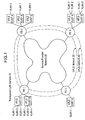
- Figure 1 illustrates one example of a Transparent LAN Service Network System in accordance with the present invention
- FIG. 2 illustrates another example of a Transparent LAN Service Network System in accordance with the present invention
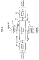
- Figure 3 illustrates one example of a Provider Edge Device in accordance with the present invention
- Figure 4 illustrates another example of a Provider Edge Device in accordance with the present invention
- Figure 5(a) illustrates one example of a packet inserted with a customer VLAN ID tag in accordance with the present invention
- Figure 5(b) illustrates one example of a packet inserted with a customer VLAN ID tag, an SP VLAN tag, and additional information in accordance with the present invention
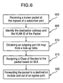
- Figure 6 illustrates one example of a method of processing a packet based on double tagging engine within a TLS network system
- Figure 7 illustrates another example of a method of processing a packet based on double tagging engine within a TLS network system
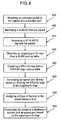
- Figure 8 illustrates yet another example of a method of processing a packet based on double tagging engine within a TLS network system
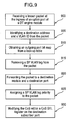
- Figure 9 illustrates one additional example of a method of processing a packet based on double tagging engine within a TLS network system.
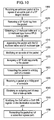
- Figure 10 illustrates another example of a method of processing a packet based on double tagging engine within a TLS network system.
- FIG 1 illustrates one example of a fast-path Transparent LAN Service (hereinafter "TLS") network system 10 that can implement double tagging.
- TLS network system 10 of this example can be configured to deliver Ethernet or other service to multiple customers geographically dispersed across a network, such as a Wide Area Network (WAN) or Metro Area Network (MAN), as if the multiple customers were connected through a Local Area Network (LAN).
- WAN Wide Area Network
- MAN Metro Area Network
- LAN Local Area Network
- the TLS network system 10 as shown in Figure 1 illustrates a Service Provider Network (SPN) 20.
- SPN 20 can be a packet switched network, such as the Internet.
- Figure 1 shows a plurality of Provider Edge (PE) devices PE 1, PE 2, PE 3 ... PE n connected to the SPN 20.
- PE Provider Edge
- Figure 1 illustrates TLS network system 10 having two VPLS customers, VPLS CUST A and VPLS CUST B. It is noted that although Figure 1 shows a TLS network system 10 having two VPLS customers, the present invention can be configured to handle a plurality of VPLS customers CUST n within the TLS network system 10.
- Each VPLS CUST A and B can be connected to a PE device.
- each VPLS customer can have its own plurality of independent Virtual Local Area Networks (VLAN), VLAN 1, VLAN 2 ... VLAN n.
- VLAN Virtual Local Area Networks
- Figure 1 shows VLAN 1, VLAN 2 ... VLAN n of VPLS CUST A being "bridged” transparently over SPN 10, wherein a Service Provider VLAN, SP VLAN 30, can be configured to specifically carry all of VPLS CUST A's communication traffic.
- Figure 1 shows VLAN 1, VLAN 2 ... VLAN n of VPLS CUST B being "bridged” transparently over SPN 10, wherein SP VLAN 40 can be configured to carry all of VPLS CUST B's communication traffic.
- FIG. 2 illustrates another example of a TLS network system 15 that can include a SPN 25 and PE devices PE 1 and PE 2.
- Each PE device can be configured to have a plurality of ports, such as at least one uplink port, upt 1 and one or more customer facing port(s), pt 0, pt 1 ... pt n.
- Each port within each of the PE devices can be configured to be a receiving port, or an ingress port, as well as a transmitting port, or an egress port, for receiving and transmitting a packet, respectively.
- the TLS network system 10, 15 of the present example can manage data and/or information in the form of a packet
- the TLS network system 10, 15 can be configured to also manage data and/or information in other formats, such as a data frame, or a data cell. Therefore, any reference to a packet herein can also refer to at least a frame, a cell, or a data packet, a data frame or a data cell.
- each port within the PE devices can be organized into groups of port(s) for one or more customer(s), wherein each organized group of port(s) can represent a VPLS domain for the TLS network system 15.
- a specific customer can be provided with one or more port(s) from the PE device.
- each port from within the organized group of port(s) assigned to the specific customer can be designated to connect with each and every VLAN of that particular customer, or selected VLANs.
- one or more customer(s) can share the same organized group of port(s) from the PE device if each customer share the same set of unique VLAN IDs.
- Figure 2 shows PE devices PE 1 and PE 2 connected to a SPN 25 via an uplink port upt1, wherein PE 1 and PE 2 can be two geographically dispersed sites.
- PE 1 and PE 2 each has a plurality of ports pt 0, pt 1, pt 2, pt 3 ... pt n therein.
- Port pt 0 of PE 1 is designated for VPLS CUST A only.
- Port pt 1 of the same PE device however is designed for two customers, them being VPLS CUST B and C.
- ports pt 3, pt 4, pt 5, pt 6, pt 7 and pt 8 are organized as a group of ports for VPLS CUST D.
- port pt 4 is designated for VPLS CUST A and port pt 5 is designated to both VPLS CUST B and C. Also, ports pt n-3, pt n-2, pt n-1 and pt n, are organized as a group of ports for VPLS CUST D.
- Figure 3 illustrates one example of a hardware configuration of a PE device.
- the hardware configuration of Figure 3 can be in an integrated, modular and single chip solution, and therefore can be embodied on a semiconductor substrate, such as silicon.
- the hardware configuration of Figure 3 can be embodied in a plurality of discrete components on a circuit board.
- Figure 3 shows a PE device that can include a double tagging engine module 300, a network module A 305, a switch fabric module 310, a network module B 315, and a network module C 320.
- the double tagging engine module 300 can have an uplink port uplink pt 325 that can be an network port for connecting to the Ethernet, such as the Internet.
- the double tagging engine module 300 can include a switch fabric port SF port a 330 for connecting to the switch fabric module 310.
- the PE device of Figure 3 also shows a network module A 305, network module B 315, and network module C 320.
- Each of the network modules A, B and C can be a network switching chip made commercially available through Broadcom® Corporation. Additionally, each of the network modules A, B and C can have one or more customer facing ports, and one switch fabric port.
- the customer facing ports can connect the PE device to the customers or subscribers of the SPN.
- the SF ports a, b and c can connect each module to the switch fabric module 310.
- the customer facing ports and the SF ports a, b and c can be an ingress port as well as an egress port.
- the switch fabric module 310 can also be a network switching chip made commercially available through Broadcom® Corporation.
- Figure 4 illustrates one example of a hardware configuration of a PE device 400.
- the hardware configuration of Figure 4 can be in an integrated, modular and single chip solution, and therefore can be embodied on a semiconductor substrate, such as silicon.
- the hardware configuration of Figure 4 can be embodied in a plurality of discrete components on a circuit board.
- the PE device 400 can be configured to include at least one uplink port uplink pt 401, and a plurality of customer facing ports or subscriber ports, pt 0, pt 1, ... pt n.
- each port within the PE device can be configured to be a receiving port, or an ingress port, as well as a transmitting port, or an egress port, for receiving and transmitting a packet, respectively.
- Figure 5(a) illustrates one example of a packet 500 that can be received in or transmitted out of any one of the customer facing ports or subscriber ports pt 0, pt 1, ... pt n.
- the packet 500 can be configured to include, at least a destination address field DA, a source address field SA, a customer VLAN identification tag VLAN ID, a type or length field T/L, and a payload P.
- the destination address field can be a bit value that can be used by the receiving Media Access Controller (MAC), in order to determine if the incoming packet is addressed to the particular port.
- MAC Media Access Controller
- the source address field can be a bit value and can be supplied by the transmitting MAC, which can inserts its own unique address into the source address field as the frame is transmitted, indicating it was the original station.
- the receiving MAC is not required to take action based on the source address field.
- the customer VLAN ID tag is a first packet tag inserted within the packet. The VLAN ID tag can identify a particular VLAN for a unique customer.
- the customer VLAN ID tag can identify the packet as originating from one of the customer's VLANs.
- the T/L field can provide the type or the length of the packet.
- the payload P can contain the actual frame data that is being transferred.
- Figure 5(b) illustrates one example of a packet 510 that can be received in or transmitted out of the uplink pt 401.
- the packet 510 can be configured to include, at least a destination address field DA, a source address field SA, an SP VLAN tag, a customer VLAN identification tag VLAN ID, an Ether-type, a SP VLAN tag priority, an op-code and a payload P.
- Packet 510 can include an SP VLAN ID tag, which can be a second tag in the packet 510.
- the SP VLAN ID tag can specify or identify a customer within the TLS network system 10. In other words, if a TLS network system 10 includes a plurality of customers, such as VPLS CUST A, VPLS CUST B, VPLS CUST C, and VPLS CUST D, the SP VLAN ID tag can identify the packet as originating from and belonging to a particular VPLS customer.
- packet 510 can include at least a first tag, that being a customer VLAN ID tag, and a second tag, that being a SP VLAN ID tag.
- the SP VLAN ID tag can identify the packet as belonging to a particular VPLS customer, and the VLAN ID tag can identify the particular VLAN belonging to that VPLS customer. Accordingly, a packet having a first and second tag can always be identified as belonging to a unique VPLS customer, even if a plurality of the VPLS customer have overlapping or common VLAN IDs.
- Figure 4 can include a storage unit 402, such as a register.
- the storage unit 402 can be configured to store a one-bit DT engine bit 403.
- the DT engine bit 403 can either be set or not set by preprogramming.
- the DT engine bit 403 can have either the value of "1" which sets the DT engine bit 403, or the value of "0" which un-set the DT engine bit 403.
- the PE device 400 can be operating under tagging engine mode.
- a bit value of "1" can indicate that the PE device 400 is operating under double tagging engine mode
- a bit value of "0" can indicate that the PE device 400 is not operating under double tagging engine mode.
- the PE device 400 of Figure 4 can be configured to include a plurality of look-up tables, such as an SP VLAN ID tag look-up table 404, a VPLS look-up table 408, a VLAN look-up table 416, an L2 multicast look-up table 420, and an L2 address look-up table 424.
- a plurality of look-up tables such as an SP VLAN ID tag look-up table 404, a VPLS look-up table 408, a VLAN look-up table 416, an L2 multicast look-up table 420, and an L2 address look-up table 424.
- the SP VLAN ID tag look-up table 404 can include one or more SP VLAN ID tag(s) 406 therein and can be indexed by a source module and a source port from a packet.
- the SP VLAN ID tag(s) 406 within the table 404 can be obtained when a packet received at the PE device 400 is to be forwarded to the uplink port 401, wherein the packet is to be double tagged.
- the VPLS look-up table 408 can have one or more entries therein.
- the VLPS look-up table 408 can be indexed by a SP VLAN ID tag so that one or more entries therein may be accessed or identified.
- Each mask entry can be configured to have a VPLS port bit map 410 or a membership port bit map therein.
- the VPLS port bit map 410 can be a bit string having a bit length that can be equal, for example, to a number of ports with the PE device 400. Each bit position of the VPLS port bit map 410 can correspond to a particular port within the PE device 400.
- the VPLS port bit map 410 can be configured to identify a group of one or more port(s) that correspond or belong to a particular VPLS membership for a PE device.
- the VPLS port bit map 410 can identify a group of one or more port(s) to which an unique customer's VLAN(s) can be mapped.
- each bit position of the VPLS port bit map 410 can be set with a value or condition of either "1" or "0".
- the port corresponding to the bit position can be included as part of the group of port(s) associated with the VPLS membership.
- the port corresponding to the bit position can be excluded from the group of port(s) associated with the VPLS membership.
- each entry within the VPLS look-up table 408 can include a Layer 2 multicast index 412 and a VPLS type 414.
- the Layer 2 multicast index 412 and the VPLS type 414 can correspond to a VPLS port bit map 410.
- FIG. 4 also shows a VLAN ID look up table 416 within the PE device 400.
- the VLAN ID look-up table 416 can include one or more preprogrammed mask entries therein. Each mask entry can be configured to be an outgoing port bit map 418.
- the outgoing bit map 418 can be a bit string having any bit length. Each bit position of the outgoing bit map 418 can correspond to a particular port of a particular module within the PE device 400 for a particular VLAN ID. In essence, the outgoing bit map 418 can be configured to identify one or more outgoing port(s) with respect to a particular VLAN ID. Accordingly, each bit position of the outgoing bit map 418 can be set with a value or condition of either "1" or "0".
- the port of a specified module corresponding to the bit position can be identified or specified as an outgoing port associated with a particular customer VLAN ID.
- the port of a specified module corresponding to the bit position can be identified or specified as not being included as an outgoing port of a particular customer VLAN ID.
- the VLAN ID look-up table 416 can be indexed by the VLAN ID tag from the packet 500 of Figure 5(a) as an example. Upon receiving the packet in an ingress port, the VLAN ID can be identified and indexed into the VLAN ID look-up table 416, wherein one VLAN ID mask entry having an outgoing port bit map 418 can be identified.
- FIG. 4 also shows an L2 Multicast look-up table 420 within the PE device 400.
- the L2 Multicast look-up table 420 can include one or more preprogrammed mask entries therein, and the size of the L2 Multicast look-up table 420 can equal to the number of multicast groups supported by the PE device 400.
- each mask entry within the L2 Multicast look-up table 420 can be accessed or identified by using the customer VLAN ID and the multicast DA within the packet received.
- Each entry can contain a list of ports which map to a L2 multicast group.
- Each mask entry within the L2 Multicast look-up table 420 can be configured to be an outgoing port bit map 422 which can be a list of ports which maps to an L2 Multicast group.
- the L2 Multicast look-up table 420 can be used to flood multicast packets to only those ports which have memberships of the L2 multicast group. In other words, rather than flooding a packet to the entire group of ports belonging to a particular VLAN ID, each outgoing port bit map 422 within the L2 Multicast table can be used to flood a packet to only the ports having membership of the L2 multicast group.
- the outgoing port bit map 422 within the L2 Multicast look-up table 420 can be a bit string having any bit length.
- Each bit position of the outgoing port bit map 422 can correspond to a particular port within the PE device 400 having an L2 multicast membership.
- the outgoing port bit map 422 can be configured to identify one or more outgoing port(s) with respect to a particular L2 multicast group. Accordingly, each bit position of the outgoing port bit map 422 can be set with a value or condition of either "1" or "0".
- the port corresponding to the bit position can be identified or specified as an outgoing port associated with a particular L2 multicast membership with respect to the packet received.
- the port corresponding to the bit position can be identified or specified as not being included as an outgoing port of a particular L2 multicast group with respect to the packet received.
- Figure 4 shows an L2 Address look-up table 424 within the PE device 400.
- the L2 Address look-up table 424 can include one or more preprogrammed mask entries therein.
- each mask entry within the L2 Address look-up table 424 can be accessed or identified by indexing the customer VLAN ID and the DA within the packet received.
- Each mask entry within the L2 Address look-up table 424 can be configured to be an outgoing port bit map 426.
- the outgoing port bit map 426 within the L2 Address look-up table 424 can be a bit string having any bit length.
- Each bit position of the outgoing port bit map 426 can correspond to a port within the PE device 400.
- the outgoing port bit map 426 can be configured to identify one or more outgoing port(s) with respect to a packet received. Similar to above, each bit position of the outgoing bit map 426 can be set with a value or condition of either "1" or "0".
- the port corresponding to the bit position can be identified or specified as an outgoing port with respect to the packet received.
- the port corresponding to the bit position can be identified or specified as not being an outgoing port with respect to the packet received.
- the PE device of Figure 3 can also include a CPU 428.
- the CPU 428 can be configured to implement a plurality of tasks and operations.
- the PE device 400 of Figure 4 can include an Ether-type configuration register 430.
- the Ether-type configuration register 430 can be configured to store an Ether-type value and can be accessed and inserted into a packet transmitted from an uplink port.
- the PE device 400 can have one or more class of service select register(s) 434 for storing a class of service type.
- the class of service select register(s) 434 can correspond to a customer port.
- Figures 6-10 illustrate one or more examples of a method of processing and double tagging a packet based on a double tagging engine thereof in accordance with the present invention.
- the method of the present example can be implemented in hardware, or software, or a combination of both hardware and software.
- Figure 6 shows one example of a method of processing a packet received on an Ethernet access port of a module based on a double tagging engine.
- a known Layer 2 unicast or a known Layer 2 multicast packet can be received at a customer subscriber port at step 600.
- a known unicast packet can be a packet that is relayed or transmitted to only one known destination port.
- a known multicast packet can be a packet that is relayed or transmitted to a multiple known destination ports.
- an unknown unicast/multicast/broadcast packet can be a destination-lookup-failure packet.
- a received packet can be an unknown unicast/multicast/broadcast packet due to a failure in the destination address (DA) lookup for the packet received. Therefore, if the destination address lookup is not successful, then the destination port or ports with respect to the packet received is unknown.
- DA destination address
- a known unicast or a known mulitcast packet can be received at one of the customer facing ports of a PE device. Once the packet is received, a destination address and a customer VLAN ID can be identified from the packet at step 605.
- an outgoing port bit map can be obtained from a look-up table at step 610. If the packet received is a known unicast packet, then the outgoing port bit map can be obtained from an L2 Address look-up table. However, if the packet received is a known multicast packet, then the outgoing port bit map can be obtained from an L2 Multicast look-up table.
- a fast filtering processor can assign a class of service (CoS) to the module header of the packet based on a service level agreement (SLA) at step 615. Thereafter, the packet can be forwarded to one or more destination module(s) and one or more egress port(s) based on the outgoing port bit map at step 620.
- CoS class of service
- SLA service level agreement
- Figure 7 shows one example of a method of processing a packet received on an Ethernet access port of a DT engine module based on a double tagging engine.
- a known Layer 2 unicast, known Layer 2 multicast, or an unknown Layer 2 unicast, multicast or broadcast packet can be received at a Ethernet access port of a DT engine module at step 700.
- a source module and a source port corresponding to the packet is identified at step 705.
- the source module and the source port indicate the source where the packet originated therefrom.
- the source module and the source port can be indexed to a SP VLAN tag look-up table to obtain a SP VLAN tag, which corresponds to the source module and the source port at step 710.
- a SP VLAN tag priority can be assigned to the packet based on the CoS of the packet at step 715.
- an Ether-type value can be obtained from an Ether-type configuration register at step 720.
- the packet received can be appended with the above information at step 725.
- the packet received at the Ethernet access port of a DT engine module can be appended with a SP VLAN tag, a SP VLAN tag priority and a Ether-type value therein.
- the packet can be forwarded out of the uplink port of the DT engine module to a SPN at step 730.
- Figure 8 shows one example of a method of processing a packet received on an Ethernet access port of a module based on a double tagging engine.
- An unknown Layer 2 unicast, multicast and broadcast packet can be received at subscriber port or a customer facing port of one or more network switching module such as Draco, or Tucana at step 800.
- a customer VLAN ID can be identified from the packet at step 805.
- a SP VLAN ID tag can be identified from the packet at step 810.
- the VLAN ID can be indexed to a VLAN ID look-up table and the SP VLAN ID tag can similarly be indexed to a SP VLAN ID look-up table.
- an outgoing port bit map can be obtained from indexing the VLAN ID to the VLAN ID look-up table at step 815, and a VPLS port bit map or a membership port bit map can also be obtained from indexing the SP VLAN ID tag to the SP VLAN ID look-up table.
- a logical AND operation can be performed on the two port bit maps to generate an egress port bit map at step 825.
- a CoS can be assigned to the packet based on a SLA at step 830, and the packet can be forwarded to one or more destination module(s) and an egress port based on the egress port bit map at step 835.
- Figure 9 shows one example of a method of processing a packet received on an uplink port or HiGig ingress port of a DT engine module based on a double tagging engine.
- a Layer 2 known unicast or a layer 2 know multicast packet can be received at the uplink port of a DT engine module at step 900.
- a destination address and a customer VLAN ID can be identified from the packet at step 905.
- an outgoing port bit map can be obtained from a look-up table at step 910. If the packet received is a known unicast packet, then the outgoing port bit map can be obtained from an L2 Address look-up table. However, if the packet received is a known multicast packet, then the outgoing port bit map can be obtained from an L2 Multicast look-up table.
- a SP VLAN ID tag can be identified and removed form the packet at step 915. Thereafter, the packet can be forwarded to one or more destination module(s) and one or more egress port(s) based on the outgoing port bit map at step 920.
- the packet can be assigned a SP VLAN tag priority to the CoS at step 925, and the CoS SEL register can be modified on the subscriber egress port(s) to match the CoS of the packet at step 930.
- Figure 10 shows one example of a method of processing a packet received on an uplink port or high Gigabit ingress port of a DT engine module based on a double tagging engine.
- a Layer 2 unknown unicast, broadcast, and multicast packet can be received at an ingress uplink port of a DT engine module at step 1000.
- a SP VLAN ID tag can be identified and removed from the packet at step 1005.
- the identified SP VLAN ID tag can be indexed to a Layer 2 multicast look-up table and obtain a L2 multicast index and a L2 multicast type from the look-up table at step 1010.
- the packet can be appended with the L2 multicast index and the L2 multicast type at step 1015.
- the operation code (op-code) within the module header of the packet can be modified to "multicast” when the multicast type appended within the packet matches a first predetermined type value at step 1020.
- the operation code (op-code) within the module header of the packet can be modified to "IP multicast" when the multicast type appended within the packet matches a second predetermined type value also at step 1020.
- a SP VLAN ID priority can be assigned to the packet's CoS at step 1025. Thereafter, the packet can be forwarded to a high Gigabit ingress port of a network switching module within a PE device at step 1030.
- the packet can be received at the high Gigabit port of a module with a PE device at step 1035.
- an outgoing port bit map can be obtained from indexing the L2 multicast look-up table at step 1040.
- the CoS SEL register can be modified on the subscriber egress port(s) to match the CoS of the packet at step 1045, and thereafter the packet can be forwarded out of one or more subscriber customer facing port(s) based on the outgoing port bit map at step 1050.
- the above-disclosed system configurations of the present invention can be embodied within a Virtual Private LAN Service (VPLS), a Transparent LAN Service (TLS), a Virtual Private Switched Network Service (VPSNS), or any Layer 2 Virtual Private Network (VPN).
- VPLS Virtual Private LAN Service
- TLS Transparent LAN Service
- VPNNS Virtual Private Switched Network Service
- the above-disclosed hardware configuration can be embodied in a semiconductor substrate, such as silicon.
- the methods of the invention can be implemented in hardware, or software, or a combination of both hardware and software.
- a person of skill in the art with respect to network system design and/or semiconductor design and manufacturing would be able to implement the various network systems, elements and methods of the present invention onto a single system or onto a single semiconductor substrate, respectively, based upon the architectural description discussed above.
Landscapes
- Engineering & Computer Science (AREA)
- Computer Networks & Wireless Communication (AREA)
- Signal Processing (AREA)
- Computer Security & Cryptography (AREA)
- Data Exchanges In Wide-Area Networks (AREA)
Applications Claiming Priority (4)
| Application Number | Priority Date | Filing Date | Title |
|---|---|---|---|
| US378937 | 1982-05-17 | ||
| US41626902P | 2002-10-07 | 2002-10-07 | |
| US416269P | 2002-10-07 | ||
| US10/378,937 US7539185B2 (en) | 2002-10-07 | 2003-03-05 | Fast-path implementation for an uplink double tagging engine |
Publications (3)
| Publication Number | Publication Date |
|---|---|
| EP1408655A2 true EP1408655A2 (de) | 2004-04-14 |
| EP1408655A3 EP1408655A3 (de) | 2006-04-12 |
| EP1408655B1 EP1408655B1 (de) | 2010-05-19 |
Family
ID=32033373
Family Applications (1)
| Application Number | Title | Priority Date | Filing Date |
|---|---|---|---|
| EP03022682A Expired - Lifetime EP1408655B1 (de) | 2002-10-07 | 2003-10-07 | Verfahren und Vorrichtung zur doppelten Kennzeichnung von Datenpaketen |
Country Status (3)
| Country | Link |
|---|---|
| US (2) | US7539185B2 (de) |
| EP (1) | EP1408655B1 (de) |
| DE (1) | DE60332591D1 (de) |
Cited By (7)
| Publication number | Priority date | Publication date | Assignee | Title |
|---|---|---|---|---|
| EP1667380A1 (de) * | 2004-12-03 | 2006-06-07 | Alcatel | Verfahren zur Übertragung von Informationen von einer Quelle zu einem Ziel über eine erste Netzwerkeinheit und ein Netzwerk und eine zweite Netzwerkeinheit. |
| CN100382531C (zh) * | 2005-10-28 | 2008-04-16 | 杭州华三通信技术有限公司 | 虚拟专网的接入方法及实现装置 |
| EP1766530A4 (de) * | 2004-07-09 | 2010-09-08 | Cisco Tech Inc | Skalierung von vlans in einem datennetzwerk |
| WO2011038050A1 (en) | 2009-09-23 | 2011-03-31 | Aerovironment, Inc | Fault-tolerant, frame-based communication system |
| GB2515363A (en) * | 2013-06-18 | 2014-12-24 | Avaya Inc | General user network interface (UNI) multi-homing techniques for shortest path bridging (SPB) networks |
| US9112785B2 (en) | 2009-09-23 | 2015-08-18 | Aerovironment, Inc. | Fault-tolerant, frame-based communication system |
| EP4044527A4 (de) * | 2019-11-07 | 2022-11-09 | ZTE Corporation | Verfahren zur weiterleitung mehrerer dienste, schalter, elektronisches gerät und lesbares medium |
Families Citing this family (67)
| Publication number | Priority date | Publication date | Assignee | Title |
|---|---|---|---|---|
| JP3521904B2 (ja) * | 2002-08-22 | 2004-04-26 | 日本電気株式会社 | イーサネット(r)におけるフレーム転送方法及びノード |
| US8225389B2 (en) * | 2003-04-11 | 2012-07-17 | Broadcom Corporation | Method and system to provide physical port security in a digital communication system |
| US7738467B2 (en) * | 2003-07-15 | 2010-06-15 | Hewlett-Packard Development Company, L.P. | Output port based double Q tagging |
| US7580409B1 (en) * | 2003-09-08 | 2009-08-25 | Extreme Networks, Inc. | System for and method of communicating control information between entities interconnected by backplane connections |
| US7839843B2 (en) * | 2003-09-18 | 2010-11-23 | Cisco Technology, Inc. | Distributed forwarding in virtual network devices |
| US7751416B2 (en) * | 2003-09-18 | 2010-07-06 | Cisco Technology, Inc. | Virtual network device |
| US8526427B1 (en) | 2003-10-21 | 2013-09-03 | Cisco Technology, Inc. | Port-based loadsharing for a satellite switch |
| US7733869B2 (en) * | 2003-12-10 | 2010-06-08 | Alcatel-Lucent | Providing VPLS-like service over native ATM networks |
| US8990430B2 (en) | 2004-02-19 | 2015-03-24 | Cisco Technology, Inc. | Interface bundles in virtual network devices |
| US8208370B1 (en) | 2004-03-31 | 2012-06-26 | Cisco Technology, Inc. | Method and system for fast link failover |
| US7889733B2 (en) * | 2004-04-28 | 2011-02-15 | Cisco Technology, Inc. | Intelligent adjunct network device |
| US7710957B2 (en) | 2004-05-19 | 2010-05-04 | Cisco Technology, Inc. | System and method for implementing multiple spanning trees per network |
| US7706364B2 (en) | 2004-05-19 | 2010-04-27 | Cisco Technology, Inc. | Virtual network device clusters |
| US7436836B2 (en) * | 2004-06-30 | 2008-10-14 | Cisco Technology, Inc. | Method and apparatus for detecting support for a protocol defining supplemental headers |
| US7808983B2 (en) | 2004-07-08 | 2010-10-05 | Cisco Technology, Inc. | Network device architecture for centralized packet processing |
| US8730976B2 (en) * | 2004-08-17 | 2014-05-20 | Cisco Technology, Inc. | System and method for preventing erroneous link aggregation due to component relocation |
| CN100438493C (zh) * | 2004-09-10 | 2008-11-26 | 华为技术有限公司 | 提高宽带接入设备用户接入容量的方法 |
| US8018964B2 (en) * | 2005-12-16 | 2011-09-13 | Cisco Technology, Inc. | Multicast operations using prioritized state information |
| US8902908B2 (en) * | 2006-05-02 | 2014-12-02 | Cisco Technology, Inc. | Support of a large number of VLANs in a bridged network |
| US8379676B1 (en) | 2006-06-01 | 2013-02-19 | World Wide Packets, Inc. | Injecting in-band control messages without impacting a data rate |
| US7760723B1 (en) * | 2006-06-01 | 2010-07-20 | World Wide Packets, Inc. | Relaying a data stream from a data device to a network tunnel |
| US7653056B1 (en) * | 2006-06-02 | 2010-01-26 | World Wide Packets, Inc. | Virtual switching using a provisional identifier to conceal a user identifier |
| US8018938B1 (en) | 2006-06-02 | 2011-09-13 | World Wide Packets, Inc. | Translating between a switching format and a transport format |
| US8379644B1 (en) * | 2006-06-30 | 2013-02-19 | Marvell International Ltd. | System and method of processing management frames |
| US7830883B1 (en) | 2006-12-19 | 2010-11-09 | World Wide Packets, Inc. | Modifying duplicate packets to have different transport formats |
| IL190433A (en) * | 2007-03-26 | 2012-07-31 | Marvell Israel Misl Ltd | System and method of modifying data packet tags |
| US8705549B2 (en) * | 2007-04-06 | 2014-04-22 | International Business Machines Corporation | Structure and implementation of universal virtual private networks |
| US20090034734A1 (en) * | 2007-07-31 | 2009-02-05 | Viasat, Inc. | Multi-Level Key Manager |
| US8125991B1 (en) * | 2007-07-31 | 2012-02-28 | Hewlett-Packard Development Company, L.P. | Network switch using managed addresses for fast route lookup |
| JP2009094832A (ja) * | 2007-10-10 | 2009-04-30 | Nec Access Technica Ltd | マルチキャストデータ配信装置、その配信方法およびその配信制御プログラム |
| US20090285207A1 (en) * | 2008-05-15 | 2009-11-19 | Cohen Yochai | System and method for routing packets using tags |
| US7916761B2 (en) * | 2008-11-03 | 2011-03-29 | The Boeing Company | Methods and apparatus for adding latency and jitter to selected network packets |
| US8885475B2 (en) * | 2010-09-10 | 2014-11-11 | Fujitsu Limited | Method and system for virtualized forwarding |
| US9571337B1 (en) * | 2010-12-22 | 2017-02-14 | Juniper Networks, Inc. | Deriving control plane connectivity during provisioning of a distributed control plane of a switch |
| US8798077B2 (en) * | 2010-12-29 | 2014-08-05 | Juniper Networks, Inc. | Methods and apparatus for standard protocol validation mechanisms deployed over a switch fabric system |
| US10171340B2 (en) * | 2011-03-24 | 2019-01-01 | Tejas Networks Limited | Interworking network element |
| US20130107887A1 (en) * | 2011-10-26 | 2013-05-02 | Mark A. Pearson | Maintaining virtual network context across multiple infrastructures |
| US8891527B2 (en) * | 2012-02-03 | 2014-11-18 | Gigamon Inc. | Systems and methods for packet filtering and switching |
| US9049233B2 (en) | 2012-10-05 | 2015-06-02 | Cisco Technology, Inc. | MPLS segment-routing |
| CN104009926B (zh) * | 2013-02-26 | 2017-04-12 | 杭州华三通信技术有限公司 | Evi网络中的组播方法及边缘设备ed |
| US9537718B2 (en) | 2013-03-15 | 2017-01-03 | Cisco Technology, Inc. | Segment routing over label distribution protocol |
| US9853822B2 (en) | 2013-09-17 | 2017-12-26 | Cisco Technology, Inc. | Bit indexed explicit replication |
| US10218524B2 (en) | 2013-09-17 | 2019-02-26 | Cisco Technology, Inc. | Bit indexed explicit replication for layer 2 networking |
| US9806897B2 (en) | 2013-09-17 | 2017-10-31 | Cisco Technology, Inc. | Bit indexed explicit replication forwarding optimization |
| US10003494B2 (en) | 2013-09-17 | 2018-06-19 | Cisco Technology, Inc. | Per-prefix LFA FRR with bit indexed explicit replication |
| US11451474B2 (en) | 2013-09-17 | 2022-09-20 | Cisco Technology, Inc. | Equal cost multi-path with bit indexed explicit replication |
| US10461946B2 (en) | 2013-09-17 | 2019-10-29 | Cisco Technology, Inc. | Overlay signaling for bit indexed explicit replication |
| US9762488B2 (en) | 2014-03-06 | 2017-09-12 | Cisco Technology, Inc. | Segment routing extension headers |
| US9807001B2 (en) | 2014-07-17 | 2017-10-31 | Cisco Technology, Inc. | Segment routing using a remote forwarding adjacency identifier |
| US9906378B2 (en) | 2015-01-27 | 2018-02-27 | Cisco Technology, Inc. | Capability aware routing |
| US10341221B2 (en) * | 2015-02-26 | 2019-07-02 | Cisco Technology, Inc. | Traffic engineering for bit indexed explicit replication |
| US10263881B2 (en) | 2016-05-26 | 2019-04-16 | Cisco Technology, Inc. | Enforcing strict shortest path forwarding using strict segment identifiers |
| US11032197B2 (en) | 2016-09-15 | 2021-06-08 | Cisco Technology, Inc. | Reroute detection in segment routing data plane |
| US10630743B2 (en) | 2016-09-23 | 2020-04-21 | Cisco Technology, Inc. | Unicast media replication fabric using bit indexed explicit replication |
| US10637675B2 (en) | 2016-11-09 | 2020-04-28 | Cisco Technology, Inc. | Area-specific broadcasting using bit indexed explicit replication |
| US10735331B1 (en) * | 2016-12-09 | 2020-08-04 | Barefoot Networks, Inc. | Buffer space availability for different packet classes |
| US10708189B1 (en) | 2016-12-09 | 2020-07-07 | Barefoot Networks, Inc. | Priority-based flow control |
| US10848429B1 (en) | 2017-03-21 | 2020-11-24 | Barefoot Networks, Inc. | Queue scheduler control via packet data |
| US10447496B2 (en) | 2017-03-30 | 2019-10-15 | Cisco Technology, Inc. | Multicast traffic steering using tree identity in bit indexed explicit replication (BIER) |
| US10164794B2 (en) | 2017-04-28 | 2018-12-25 | Cisco Technology, Inc. | Bridging of non-capable subnetworks in bit indexed explicit replication |
| FR3072233B1 (fr) * | 2017-10-10 | 2020-11-27 | Bull Sas | Procede de generation de requetes pour la segmentation de la surveillance d'un reseau d'interconnexion et materiel associe |
| US11140074B2 (en) | 2019-09-24 | 2021-10-05 | Cisco Technology, Inc. | Communicating packets across multi-domain networks using compact forwarding instructions |
| CN112583510B (zh) * | 2019-09-30 | 2025-01-10 | 华为技术有限公司 | 一种报文转发方法、设备及系统 |
| JP7492127B2 (ja) * | 2020-06-09 | 2024-05-29 | 富士通株式会社 | 通信装置及び通信方法 |
| EP4275336A1 (de) | 2021-01-06 | 2023-11-15 | ADTRAN, Inc. | Kommunikationssicherheit in einem netzwerk |
| EP4589913A3 (de) * | 2021-03-23 | 2025-08-20 | Adtran, Inc. | Kommunikationssicherheit in einem netzwerk |
| US11665087B2 (en) | 2021-09-15 | 2023-05-30 | International Business Machines Corporation | Transparent service-aware multi-path networking with a feature of multiplexing |
Family Cites Families (34)
| Publication number | Priority date | Publication date | Assignee | Title |
|---|---|---|---|---|
| US5394402A (en) * | 1993-06-17 | 1995-02-28 | Ascom Timeplex Trading Ag | Hub for segmented virtual local area network with shared media access |
| US5617421A (en) * | 1994-06-17 | 1997-04-01 | Cisco Systems, Inc. | Extended domain computer network using standard links |
| US6035105A (en) * | 1996-01-02 | 2000-03-07 | Cisco Technology, Inc. | Multiple VLAN architecture system |
| US6085238A (en) * | 1996-04-23 | 2000-07-04 | Matsushita Electric Works, Ltd. | Virtual LAN system |
| US6236643B1 (en) * | 1997-02-14 | 2001-05-22 | Advanced Micro Devices, Inc. | Multiport data switch having variable maximum packet length |
| US6041057A (en) * | 1997-03-24 | 2000-03-21 | Xylan Corporation | Self-configuring ATM network |
| US5938736A (en) * | 1997-06-30 | 1999-08-17 | Sun Microsystems, Inc. | Search engine architecture for a high performance multi-layer switch element |
| US5991297A (en) * | 1997-08-28 | 1999-11-23 | Ascend Communications | Independently sizable memory pages for a plurality of connection ID types in a network switch |
| US6115379A (en) * | 1997-09-11 | 2000-09-05 | 3Com Corporation | Unicast, multicast, and broadcast method and apparatus |
| US6339595B1 (en) * | 1997-12-23 | 2002-01-15 | Cisco Technology, Inc. | Peer-model support for virtual private networks with potentially overlapping addresses |
| US6728249B2 (en) * | 1998-06-27 | 2004-04-27 | Intel Corporation | System and method for performing cut-through forwarding in an ATM network supporting LAN emulation |
| US6181699B1 (en) * | 1998-07-01 | 2001-01-30 | National Semiconductor Corporation | Apparatus and method of assigning VLAN tags |
| GB9824594D0 (en) * | 1998-11-11 | 1999-01-06 | 3Com Technologies Ltd | Modifying tag fields in ethernet data packets |
| US6937574B1 (en) * | 1999-03-16 | 2005-08-30 | Nortel Networks Limited | Virtual private networks and methods for their operation |
| US6788681B1 (en) * | 1999-03-16 | 2004-09-07 | Nortel Networks Limited | Virtual private networks and methods for their operation |
| US6553028B1 (en) * | 1999-04-30 | 2003-04-22 | Cisco Technology, Inc. | Method and apparatus for multicast switching using a centralized switching engine |
| US6778547B1 (en) * | 1999-05-21 | 2004-08-17 | Advanced Micro Devices, Inc. | Method and apparatus for improving throughput of a rules checker logic |
| US6633565B1 (en) * | 1999-06-29 | 2003-10-14 | 3Com Corporation | Apparatus for and method of flow switching in a data communications network |
| US6901452B1 (en) * | 2000-03-02 | 2005-05-31 | Alcatel | Selectable prioritization for data communication switch |
| US6862280B1 (en) * | 2000-03-02 | 2005-03-01 | Alcatel | Priority remapping for data communication switch |
| US6693909B1 (en) * | 2000-05-05 | 2004-02-17 | Fujitsu Network Communications, Inc. | Method and system for transporting traffic in a packet-switched network |
| US6965572B1 (en) * | 2000-06-07 | 2005-11-15 | At&T Corp. | Loopback capability for bi-directional multi-protocol label switching traffic engineered trucks |
| JP4126856B2 (ja) * | 2000-07-07 | 2008-07-30 | 沖電気工業株式会社 | Tag−vlanのid自動識別方法 |
| US20020062415A1 (en) * | 2000-09-29 | 2002-05-23 | Zarlink Semiconductor N.V. Inc. | Slotted memory access method |
| JP4183379B2 (ja) * | 2000-11-27 | 2008-11-19 | 富士通株式会社 | ネットワーク及びエッジルータ |
| US6618388B2 (en) * | 2001-01-05 | 2003-09-09 | Extreme Networks | Method and system for VMAN protocol |
| US7136355B2 (en) * | 2001-01-16 | 2006-11-14 | Admtek Incorporated | Transmission components for processing VLAN tag and priority packets supported by using single chip's buffer structure |
| US7242665B2 (en) * | 2001-01-25 | 2007-07-10 | Ericsson Ab | Network device virtual interface |
| US7092389B2 (en) * | 2001-01-30 | 2006-08-15 | At&T Corp. | Technique for ethernet access to packet-based services |
| US20020176450A1 (en) * | 2001-01-31 | 2002-11-28 | Sycamore Networks, Inc. | System and methods for selectively transmitting ethernet traffic over SONET/SDH optical network |
| JP4192446B2 (ja) * | 2001-06-29 | 2008-12-10 | 株式会社日立製作所 | 通信サービス取引方法および通信システム |
| US20030152075A1 (en) * | 2002-02-14 | 2003-08-14 | Hawthorne Austin J. | Virtual local area network identifier translation in a packet-based network |
| US7095738B1 (en) * | 2002-05-07 | 2006-08-22 | Cisco Technology, Inc. | System and method for deriving IPv6 scope identifiers and for mapping the identifiers into IPv6 addresses |
| US7180899B2 (en) * | 2002-10-29 | 2007-02-20 | Cisco Technology, Inc. | Multi-tiered Virtual Local area Network (VLAN) domain mapping mechanism |
-
2003
- 2003-03-05 US US10/378,937 patent/US7539185B2/en not_active Expired - Fee Related
- 2003-10-07 DE DE60332591T patent/DE60332591D1/de not_active Expired - Lifetime
- 2003-10-07 EP EP03022682A patent/EP1408655B1/de not_active Expired - Lifetime
-
2009
- 2009-04-21 US US12/427,553 patent/US20090196289A1/en not_active Abandoned
Cited By (13)
| Publication number | Priority date | Publication date | Assignee | Title |
|---|---|---|---|---|
| EP1766530A4 (de) * | 2004-07-09 | 2010-09-08 | Cisco Tech Inc | Skalierung von vlans in einem datennetzwerk |
| US8094657B2 (en) | 2004-12-03 | 2012-01-10 | Alcatel Lucent | Method for transmitting information from a source via a first network unit and a network and a second network unit to a destination |
| WO2006058612A1 (en) * | 2004-12-03 | 2006-06-08 | Alcatel Lucent | Method for transmitting information from a source via a first network unit and a network and a second network unit to a destination |
| EP1667380A1 (de) * | 2004-12-03 | 2006-06-07 | Alcatel | Verfahren zur Übertragung von Informationen von einer Quelle zu einem Ziel über eine erste Netzwerkeinheit und ein Netzwerk und eine zweite Netzwerkeinheit. |
| CN100382531C (zh) * | 2005-10-28 | 2008-04-16 | 杭州华三通信技术有限公司 | 虚拟专网的接入方法及实现装置 |
| EP2480982A4 (de) * | 2009-09-23 | 2013-10-16 | Aerovironment Inc | Fehlertolerantes rahmenbasiertes kommunikationssystem |
| WO2011038050A1 (en) | 2009-09-23 | 2011-03-31 | Aerovironment, Inc | Fault-tolerant, frame-based communication system |
| US9112785B2 (en) | 2009-09-23 | 2015-08-18 | Aerovironment, Inc. | Fault-tolerant, frame-based communication system |
| US9735980B2 (en) | 2009-09-23 | 2017-08-15 | Aerovironment, Inc. | Fault-tolerant, frame-based communication system |
| GB2515363A (en) * | 2013-06-18 | 2014-12-24 | Avaya Inc | General user network interface (UNI) multi-homing techniques for shortest path bridging (SPB) networks |
| US9860081B2 (en) | 2013-06-18 | 2018-01-02 | Extreme Networks, Inc. | General user network interface (UNI) multi-homing techniques for shortest path bridging (SPB) networks |
| GB2515363B (en) * | 2013-06-18 | 2021-05-19 | Extreme Networks Inc | General user network interface (UNI) multi-homing techniques for shortest path bridging (SPB) networks |
| EP4044527A4 (de) * | 2019-11-07 | 2022-11-09 | ZTE Corporation | Verfahren zur weiterleitung mehrerer dienste, schalter, elektronisches gerät und lesbares medium |
Also Published As
| Publication number | Publication date |
|---|---|
| EP1408655A3 (de) | 2006-04-12 |
| US7539185B2 (en) | 2009-05-26 |
| EP1408655B1 (de) | 2010-05-19 |
| DE60332591D1 (de) | 2010-07-01 |
| US20090196289A1 (en) | 2009-08-06 |
| US20040066781A1 (en) | 2004-04-08 |
Similar Documents
| Publication | Publication Date | Title |
|---|---|---|
| US7539185B2 (en) | Fast-path implementation for an uplink double tagging engine | |
| US7636319B2 (en) | Fastpath implementation for a double tagging loopback engine | |
| US7515592B2 (en) | Fast-path implementation for transparent LAN services using double tagging | |
| US6430621B1 (en) | System using different tag protocol identifiers to distinguish between multiple virtual local area networks | |
| US6147995A (en) | Method for establishing restricted broadcast groups in a switched network | |
| US7593400B2 (en) | MAC address learning in a distributed bridge | |
| US6914905B1 (en) | Method and system for VLAN aggregation | |
| US7095738B1 (en) | System and method for deriving IPv6 scope identifiers and for mapping the identifiers into IPv6 addresses | |
| US7548541B2 (en) | Managing VLAN traffic in a multiport network node using customer-specific identifiers | |
| EP2057796B1 (de) | Punkt-zu-mehrpunkt-funktionalität in einem überbrückten netzwerk | |
| US20030152075A1 (en) | Virtual local area network identifier translation in a packet-based network | |
| US20040184408A1 (en) | Ethernet architecture with data packet encapsulation | |
| US7154899B2 (en) | Protecting the filtering database in virtual bridges | |
| US20050138149A1 (en) | Method and system for increasing available user VLAN space | |
| CN1816991A (zh) | 用于媒体访问控制地址学习的源标识符 | |
| KR20040107379A (ko) | 분산 구조 라우터에서 가상 근거리 통신망 브리징 및 가상사설 통신망을 구현하는 장치 및 방법 | |
| US8873431B1 (en) | Communications system and method for maintaining topology in a VLAN environment | |
| CN100391196C (zh) | 基于虚拟局域网的数据交换方法 | |
| CN101453401A (zh) | 以太网桥设备及mac地址学习方法和数据报文传输方法 | |
| Gashinsky | TRILL working group L. Dunbar Internet Draft D. Eastlake Intended status: Standard Track Huawei Expires: Sept 2012 Radia Perlman Intel | |
| IL195263A (en) | Learning a Macintosh address on a distributed bridge |
Legal Events
| Date | Code | Title | Description |
|---|---|---|---|
| PUAI | Public reference made under article 153(3) epc to a published international application that has entered the european phase |
Free format text: ORIGINAL CODE: 0009012 |
|
| AK | Designated contracting states |
Kind code of ref document: A2 Designated state(s): AT BE BG CH CY CZ DE DK EE ES FI FR GB GR HU IE IT LI LU MC NL PT RO SE SI SK TR |
|
| AX | Request for extension of the european patent |
Extension state: AL LT LV MK |
|
| RIN1 | Information on inventor provided before grant (corrected) |
Inventor name: YU, SONG-HUO Inventor name: SHANKAR, LAXMAN Inventor name: AMBE, SHEKHAR |
|
| PUAL | Search report despatched |
Free format text: ORIGINAL CODE: 0009013 |
|
| AK | Designated contracting states |
Kind code of ref document: A3 Designated state(s): AT BE BG CH CY CZ DE DK EE ES FI FR GB GR HU IE IT LI LU MC NL PT RO SE SI SK TR |
|
| AX | Request for extension of the european patent |
Extension state: AL LT LV MK |
|
| 17P | Request for examination filed |
Effective date: 20061012 |
|
| AKX | Designation fees paid |
Designated state(s): DE FR GB |
|
| 17Q | First examination report despatched |
Effective date: 20070411 |
|
| RAP1 | Party data changed (applicant data changed or rights of an application transferred) |
Owner name: BROADCOM CORPORATION |
|
| GRAP | Despatch of communication of intention to grant a patent |
Free format text: ORIGINAL CODE: EPIDOSNIGR1 |
|
| GRAS | Grant fee paid |
Free format text: ORIGINAL CODE: EPIDOSNIGR3 |
|
| GRAA | (expected) grant |
Free format text: ORIGINAL CODE: 0009210 |
|
| AK | Designated contracting states |
Kind code of ref document: B1 Designated state(s): DE FR GB |
|
| REG | Reference to a national code |
Ref country code: GB Ref legal event code: FG4D |
|
| REF | Corresponds to: |
Ref document number: 60332591 Country of ref document: DE Date of ref document: 20100701 Kind code of ref document: P |
|
| PLBE | No opposition filed within time limit |
Free format text: ORIGINAL CODE: 0009261 |
|
| STAA | Information on the status of an ep patent application or granted ep patent |
Free format text: STATUS: NO OPPOSITION FILED WITHIN TIME LIMIT |
|
| 26N | No opposition filed |
Effective date: 20110222 |
|
| REG | Reference to a national code |
Ref country code: DE Ref legal event code: R097 Ref document number: 60332591 Country of ref document: DE Effective date: 20110221 |
|
| PG25 | Lapsed in a contracting state [announced via postgrant information from national office to epo] |
Ref country code: FR Free format text: LAPSE BECAUSE OF NON-PAYMENT OF DUE FEES Effective date: 20101102 |
|
| REG | Reference to a national code |
Ref country code: FR Ref legal event code: ST Effective date: 20110630 |
|
| REG | Reference to a national code |
Ref country code: DE Ref legal event code: R082 Ref document number: 60332591 Country of ref document: DE Representative=s name: BOSCH JEHLE PATENTANWALTSGESELLSCHAFT MBH, DE Ref country code: DE Ref legal event code: R081 Ref document number: 60332591 Country of ref document: DE Owner name: AVAGO TECHNOLOGIES INTERNATIONAL SALES PTE. LT, SG Free format text: FORMER OWNER: BROADCOM CORP., IRVINE, CALIF., US Ref country code: DE Ref legal event code: R081 Ref document number: 60332591 Country of ref document: DE Owner name: AVAGO TECHNOLOGIES GENERAL IP (SINGAPORE) PTE., SG Free format text: FORMER OWNER: BROADCOM CORP., IRVINE, CALIF., US |
|
| REG | Reference to a national code |
Ref country code: GB Ref legal event code: 732E Free format text: REGISTERED BETWEEN 20171005 AND 20171011 |
|
| REG | Reference to a national code |
Ref country code: DE Ref legal event code: R081 Ref document number: 60332591 Country of ref document: DE Owner name: AVAGO TECHNOLOGIES INTERNATIONAL SALES PTE. LT, SG Free format text: FORMER OWNER: AVAGO TECHNOLOGIES GENERAL IP (SINGAPORE) PTE. LTD., SINGAPORE, SG Ref country code: DE Ref legal event code: R082 Ref document number: 60332591 Country of ref document: DE Representative=s name: BOSCH JEHLE PATENTANWALTSGESELLSCHAFT MBH, DE |
|
| REG | Reference to a national code |
Ref country code: GB Ref legal event code: 732E Free format text: REGISTERED BETWEEN 20190222 AND 20190227 |
|
| PGFP | Annual fee paid to national office [announced via postgrant information from national office to epo] |
Ref country code: GB Payment date: 20201027 Year of fee payment: 18 |
|
| GBPC | Gb: european patent ceased through non-payment of renewal fee |
Effective date: 20211007 |
|
| PG25 | Lapsed in a contracting state [announced via postgrant information from national office to epo] |
Ref country code: GB Free format text: LAPSE BECAUSE OF NON-PAYMENT OF DUE FEES Effective date: 20211007 |
|
| PGFP | Annual fee paid to national office [announced via postgrant information from national office to epo] |
Ref country code: DE Payment date: 20220616 Year of fee payment: 20 |
|
| REG | Reference to a national code |
Ref country code: DE Ref legal event code: R071 Ref document number: 60332591 Country of ref document: DE |