EP1408665B1 - Erfassung der Lage von Pilotsymbolen in einem Mehrträgersignal - Google Patents
Erfassung der Lage von Pilotsymbolen in einem Mehrträgersignal Download PDFInfo
- Publication number
- EP1408665B1 EP1408665B1 EP03023128.6A EP03023128A EP1408665B1 EP 1408665 B1 EP1408665 B1 EP 1408665B1 EP 03023128 A EP03023128 A EP 03023128A EP 1408665 B1 EP1408665 B1 EP 1408665B1
- Authority
- EP
- European Patent Office
- Prior art keywords
- complex
- symbols
- ofdm signal
- symbol
- equalization
- Prior art date
- Legal status (The legal status is an assumption and is not a legal conclusion. Google has not performed a legal analysis and makes no representation as to the accuracy of the status listed.)
- Expired - Lifetime
Links
Images





Classifications
-
- H—ELECTRICITY
- H04—ELECTRIC COMMUNICATION TECHNIQUE
- H04L—TRANSMISSION OF DIGITAL INFORMATION, e.g. TELEGRAPHIC COMMUNICATION
- H04L27/00—Modulated-carrier systems
- H04L27/26—Systems using multi-frequency codes
- H04L27/2601—Multicarrier modulation systems
- H04L27/2647—Arrangements specific to the receiver only
- H04L27/2655—Synchronisation arrangements
- H04L27/2656—Frame synchronisation, e.g. packet synchronisation, time division duplex [TDD] switching point detection or subframe synchronisation
-
- H—ELECTRICITY
- H04—ELECTRIC COMMUNICATION TECHNIQUE
- H04L—TRANSMISSION OF DIGITAL INFORMATION, e.g. TELEGRAPHIC COMMUNICATION
- H04L27/00—Modulated-carrier systems
- H04L27/26—Systems using multi-frequency codes
- H04L27/2601—Multicarrier modulation systems
- H04L27/2647—Arrangements specific to the receiver only
- H04L27/2655—Synchronisation arrangements
- H04L27/2668—Details of algorithms
- H04L27/2673—Details of algorithms characterised by synchronisation parameters
- H04L27/2675—Pilot or known symbols
-
- H—ELECTRICITY
- H04—ELECTRIC COMMUNICATION TECHNIQUE
- H04L—TRANSMISSION OF DIGITAL INFORMATION, e.g. TELEGRAPHIC COMMUNICATION
- H04L25/00—Baseband systems
- H04L25/02—Details ; arrangements for supplying electrical power along data transmission lines
- H04L25/03—Shaping networks in transmitter or receiver, e.g. adaptive shaping networks
- H04L25/03006—Arrangements for removing intersymbol interference
- H04L2025/0335—Arrangements for removing intersymbol interference characterised by the type of transmission
- H04L2025/03375—Passband transmission
- H04L2025/03414—Multicarrier
-
- H—ELECTRICITY
- H04—ELECTRIC COMMUNICATION TECHNIQUE
- H04L—TRANSMISSION OF DIGITAL INFORMATION, e.g. TELEGRAPHIC COMMUNICATION
- H04L27/00—Modulated-carrier systems
- H04L27/26—Systems using multi-frequency codes
- H04L27/2601—Multicarrier modulation systems
- H04L27/2602—Signal structure
- H04L27/261—Details of reference signals
- H04L27/2613—Structure of the reference signals
-
- H—ELECTRICITY
- H04—ELECTRIC COMMUNICATION TECHNIQUE
- H04L—TRANSMISSION OF DIGITAL INFORMATION, e.g. TELEGRAPHIC COMMUNICATION
- H04L27/00—Modulated-carrier systems
- H04L27/26—Systems using multi-frequency codes
- H04L27/2601—Multicarrier modulation systems
- H04L27/2647—Arrangements specific to the receiver only
- H04L27/2655—Synchronisation arrangements
- H04L27/2662—Symbol synchronisation
Definitions
- the present invention relates to an OFDM equalization apparatus, and in particular to a technique for equalizing an OFDM signal used in digital terrestrial broadcasting.
- an OFDM signal is a signal obtained by modulating each of a multiplicity of mutually orthogonal carriers with digital data, and multiplexing the modulated waves.
- transstyrene-based broadcast signal(s) The standard for OFDM signals used in Japanese terrestrial digital broadcasting (hereinafter simply referred to as “terrestrial digital broadcast signal(s)") is defined in Non-patent document 1. The following describes parts of this standard that are relevant to the subject of the present invention.
- a terrestrial digital broadcast signal is composed of 13 OFDM segments (hereinafter simply called “segment(s)”) in the case of a television broadcast, and one or three segments in the case of a radio broadcast.
- Segment(s) Each segment is a bundle of carriers, and has a bandwidth of approximately 430 kHz.
- the number of carriers is predetermined according to the transmission mode, and is, for example, 108 in mode 1.
- a control information carrier is modulated using a known modulation method.
- a data carrier transmits information of the broadcast itself, and is modulated using the modulation method indicated by the control information.
- a segment in which data carriers are modulated with QPSK (Quarternary Phase Shrift Modulation), 16 QAM (Quadrature Amplitude Modulation), or 64 QAM is called a synchronous modulation portion, and a segment in which data carriers are modulated with DQPSK (Differential QPSK) is called a differential modulation portion.
- Each carrier is modulated with an individual complex symbol (a so-called IQ symbol that represents the orthogonal component of the information signal as a real part and an imaginary part) each symbol period, and the modulated carriers are transmitted multiplexed as one OFDM signal.
- IQ symbol that represents the orthogonal component of the information signal as a real part and an imaginary part
- Two hundred and four OFDM symbols make up one transmission frame (hereinafter simply referred to as a "frame").
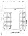
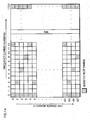
- FIG. 10 shows an example of the configuration of a frame in a synchronous modulation portion.
- carriers are shown arranged from left to right in ascending order of frequency, and from top to bottom in temporal order of OFDM symbols.
- the carrier number k is 0 to 107 in the ascending order of frequency
- the symbol number n is 0 to 203 in the temporal order within the frame.
- FIG. 10 also shows the arrangement of carrier frequency order and temporal order of the complex symbols c(n,k).
- SP symbols are transmitted in the synchronous modulation portion.
- An SP symbol is a pilot symbol that indicates a reference value used in signal equalization. As shown in FIG. 10 , an SP symbol is transmitted once every four symbol periods in temporal order by one in three carriers. This means that in terms of frequency order an SP symbol is transmitted by one in twelve carriers in every symbol period.
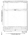
- FIG. 11 shows an example of the configuration in a frame of a differential modulation portion, using the same notation as FIG. 10 . SP symbols are not transmitted in the differential modulation portion.
- a TMCC (transmission and multiplexing configuration control) signal is transmitted using a predetermined carrier in both the synchronous modulation portion and the differential modulation portion.
- the TMCC signal includes synchronizing symbols in symbol numbers 1 to 16, segment type identification symbols in symbol numbers 17 to 19, and TMCC information symbols in symbol numbers 20 to 121.
- the synchronizing symbols indicate synchronization timing of the frame.
- the TMCC information symbols can be used to identify whether the segment is a synchronous modulation portion or a differential modulation portion.
- Patent Document 1 Conventional OFDM signal reception apparatuses that receive such terrestrial digital broadcast signals have been disclosed in, for example, Patent Document 1.
- FIG. 12 is a functional block diagram showing the structure of a terrestrial digital broadcast reception apparatus 9 that includes an audio/video playback unit 80 and a display unit 90 in addition to the main components of the OFDM signal reception apparatus shown in Patent Document 1.
- an antenna 10 receives an RF band OFDM signal SRF(t)
- a tuner 20 converts the frequency of the signal SRF(t) to an IF band OFDM signal SIF(t) with use of a signal generated by a local oscillator inside of the tuner 20,
- an A/D unit 30 samples the signal SIF(T) and outputs data D(t), and
- an orthogonal demodulation unit 40 outputs a baseband OFDM signal B(t) based on the data D(t).
- the signal B(t) represents a series of complex values that represents the orthogonal components included in a time domain OFDM signal with a real part and an imaginary part.
- the sections throughwhich the complex signal passes are indicated by a thick line in FIG. 12 .
- An FFT unit 50 converts by Fourier transformation the signal B(t) obtained in the valid symbol period of the symbol number n to calculate, for each carrier, a complex symbol c(n,k) represented by carrier k (in other words, a complex symbol c(n, k) that is the modulated carrier k) in that period.
- the TMCC processing unit 51 establishes frame synchronization and identifies segment type by referring to the complex symbol c(n,k0) calculated for the carrier k0 that transmits a TMCC signal.
- the TMCC processing unit 51 then notifies an equalization unit 60 of frame synchronizing information indicating the established frame synchronous timing, and segment type information vindicating the identified segment type.
- the equalization unit 60 specifies the position of the SP symbols based on the notified frame synchronization information, and equalizes the phase and amplitude of each of the complex symbols with use of the complex symbols that are in the specif iedposition.
- An error correction unit 70 corrects errors in the equalized complex symbols d(n,k) and converts the corrected complex symbols d(n,k) to a transport stream TS.
- the audio/video playback unit 80 decodes the transport stream to obtain an audio/video signal, and outputs video and audio via the display unit 90.
- the equalization unit 60 in the conventional terrestrial digital broadcast reception apparatus commences equalizing the complex symbols only once it has been notified of the segment type information and the frame synchronization information by the TMCC processing unit 51.
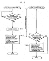
- FIG. 13 is a flowchart showing details of conventional equalization processing.
- the TMCC processing unit 51 establishes synchronization (S11), decodes the TMCC information symbols (S12), and provides the frame synchronization information and the segment type information to the equalization unit 60 (S13).
- the equalization unit 60 refers to the segment type information notified by the TMCC processing unit 51, and if the segment is a synchronous modulation portion (S24: YES), commences equalization (S25).
- Two frames' worth of time is approximately 0.5 seconds, defending on the transmission mode. This gives rise to a problem that a considerable amount of time is required to obtain stable audio and video with conventional equalization processing.
- This problem occurs not only in Japanese terrestrial digital broadcasting, but generally occurs in digital broadcasts, such as in European terrestrial digital broadcasting, that are transmitted by an OFDM signal having a similar configuration to that described, and received according to a procedure of specifying the position of the SP symbols after establishing synchronization and then commencing equalization processing.
- FIG. 14 shows an example of the configuration in a frame of an OFDM signal used in European terrestrial digital broadcasting, using the same notation as FIG. 10 .
- This OFDM signal transmits boosted pilot symbols that correspond to SP symbols, and a TPS signal that corresponds to a TMCC symbol. Details of European terrestrial digital broadcasting can be found in Non-Patent Document 2.
- EP 0 898 381 A2 discloses technology for identifying a pilot symbol by obtaining equalization between signals in a reference signal sequence and a received signal sequence.
- the object of the present invention is to provide: an OFDM signal equalization apparatus that is capable of specifying the position of pilot symbols and commencing equalization within a short amount time, compared to a conventional apparatus, after complex symbols represented by a frequency domain OFDM signal begin to be provided; a method and program therefore; and a terrestrial digital broadcast reception apparatus to which the OFDM signal equalization is applied.
- An OFDM signal equalization apparatus according to the invention is provided in claim 1. According to the claimed structure, the OFDM signal equalization apparatus determines groups using periodicity found when the complex symbols are arranged in the predetermined order, and evaluates the correlation between complex symbols in each group in order to specify the complex symbols that are the pilot symbols for use in equalization of the OFDM signal.
- the OFDM signal equalization apparatus is able to specify the pilot symbols using complex symbols of several to several tens of symbol periods, and commence equalization processing.
- the amount of time required for the OFDM signal equalization apparatus to commence equalization processing is shorter than when using a conventional technique which requires 1.5 to 2 frames of time.
- equalization processing can be performed using complex symbols specified as pilot symbols using synchronized frames as a reference. Therefore, there is less chance that synchronization, and therefore the pilot symbols, will be lost than when the pilot symbols continue to be specified using of the correlation within each group as a reference, in addition to the effect of being able to commence equalization processing within a short period of time.
- An OFDM signal equalization method according to the invention is provided in claim 12.
- a computer executable program according to the invention is provided in claim 22. Further embodiments of the invention are provided in the dependent claims.
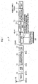
- FIG. 1 is a functional block diagram showing the overall structure of the terrestrial digital broadcast reception apparatus.
- the terrestrial digital broadcast reception apparatus 1 differs from the terrestrial digital broadcast reception apparatus 9 in that it has an equalization control unit 58 that is the OFDM signal equalization apparatus of the present invention, and an equalization unit 65 that operates in cooperation with the equalization control unit 58.
- the units of the terrestrial digital broadcast reception apparatus 1 may be implemented in the following manner.
- the tuner 20 may be implemented by, for example, a high frequency analog circuit that is operable in an RF band.
- the A/D unit 30 through to the audio/video playback unit 80 may be implemented with use of, for example, a DPS (digital signal processor), a ROM (read only memory), and a RAM (random access memory).
- the units represent each function carried out by the DSP executing a program recorded in the ROM. Data processed by the units is stored in the RAM, and is also passed between the units via the RAM.
- the units may be implemented with use of ASICs (application specific integrated circuits) or the like as special-purpose hardware circuits for carrying out the respective functions.
- the display unit 90 is an audio/videomonitor apparatus that is implemented with a PDP (plasma display panel), an LCD (liquid crystal display), a CRT (cathode ray tube), or the like.
- PDP plasma display panel
- LCD liquid crystal display
- CRT cathode ray tube
- FIGs. 2A and 2B each show an example of the external appearance of the terrestrial digital broadcast reception apparatus 1.
- FIG. 2A shows an example of the external appearance of the terrestrial digital broadcast reception apparatus 1 embodied as a fixed-type STB (set top box).
- FIG. 2B shows an example of the external appearance of the terrestrial digital broadcast reception apparatus 1 embodied as a mobile terminal apparatus.
- the equalization control unit 58 is provided with complex symbols, which are the same as conventional complex symbols, from the FFT unit 50, and specifies in a shorter amount of time than the conventional TMCC processing unit 51 whether SP symbols are present among the complex symbols and the position of the SP symbols. The equalization control unit 58 then notifies the equalization unit 65 whether SP symbols are present, and the position of the SP symbols.
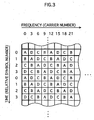
- FIG. 3 is a conceptual drawing showing four groups of complex symbols that are possibly SP symbols, in a state in which frame synchronization has not been established (in other words, the symbol numbers of the complex symbols are undetermined).
- FIG. 3 shows the complex symbols of only carriers engaged in SP symbol transmission arranged in carrier frequency order and temporal order.
- every fourth complex symbol in temporal order is an SP symbol. Furthermore, in each symbol period, every fourth complex symbol in carrier frequency order is an SP symbol. In other words, all complex symbols in one of the groups A to D shown in FIG. 3 are SP symbols. Note that the groups are determined according to relative symbol numbers that recur every four symbol periods.
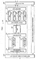
- FIG. 4 is a functional block diagram showing the structure of the equalization control unit 58 in detail.
- a TMCC processing unit 52 after establishing frame synchronization and decoding TMCC information symbols, outputs TMCC validity information, and also outputs frame synchronization information and segment type information which are the same those in the conventional art.
- the SP detection unit 53 specifies whether any SP symbols exist and the position of the SP symbols, by calculating, for each group, an index showing the correlation between the complex symbols in the group. The SP detection unit 53 then outputs SP detection information indicating that the specified SP symbols exist, and four-symbol synchronization information showing the specified position of the SP symbols.
- a selector 54 selects the SP detection information if TMCC validity information has not been output, and selects the segment type information if TMCC validity information has been output. The selector 54 then outputs the selected information as SP existence information.
- a selector 55 selects the four-symbol synchronization information if TMCC validity information is not output, and selects the frame synchronization information if TMCC validity information is output. The selector 55 then outputs the selected information as SP position information.
- FIG. 5 is a functional block diagram showing the structure of the SP detection unit 53 in detail.
- the SP detection unit 53 is provided with complex symbols by the FFT unit 50 in a state in which frame synchronization has not been established.
- the FFT unit 50 is described as de-multiplexing one OFDM symbol into complex symbols that correspond to each of the carriers in one symbol period, and successively providing the complex symbols to the SP detection unit 53 in order of carrier frequency.
- carriers referred to here are the carriers of all segments that make up a terrestrial digital broadcast signal.
- the SP detection unit 53 is provided by the FFT unit 50 with serial numbers of the carriers across all segments, the serial numbers corresponding to the complex symbols represented by the carriers.
- a first complex symbol sorting unit 100 sorts each complex symbol one segment according to the serial number of the carrier that corresponds to the complex symbol. In other words, the first complex symbol sorting unit 100 outputs each complex symbol to a carrier sorting unit corresponding to the segment.
- the second complex symbol sorting unit 110 successively receives complex symbols represented by the carriers in the segment in carrier frequency order.
- the four-symbol delay units 121, 122, etc. correspond respectively to the carriers that are engaged in SP symbol transmission.
- the second complex symbol sorting unit 110 outputs received complex symbols that are represented by carriers engaged in SP symbol transmission to both the four-symbol delay unit corresponding to the carrier and the selection unit 130.
- Each of the four symbol delay units 121, 122, etc. holds four received complex symbols, and on receiving a new complex symbol from the second complex symbol sorting unit 110, outputs the oldest of the held complex symbols to the selection unit 130, and replaces the oldest complex symbol with the new complex symbol.
- the four-symbol delay units 121, 122, etc. receive one complex symbol every symbol period, and delay each received complex symbol for four symbol periods.
- the selection unit 130 receives one new complex symbol sorted into one of the carriers from the second complex symbol sorting unit 110, and receives the oldest complex symbol from the four symbol delay unit corresponding to the carrier. The selection unit 130 selects both of the received complex symbols, and outputs the selected symbols to the calculation unit 140.
- the calculation unit 140 performs one of the following calculations on the two complex symbols received from the selection unit 130: (a) complex division of one complex symbol with the other complex symbol; (b) complex multiplication of the complex conjugate value of one of the complex symbols with the other complex symbol; and (c) complex multiplication of the complex conjugate value of one of the complex symbols with the other complex symbol and normalization of the result of the complex multiplication.
- the calculation unit 140 then outputs the result of the calculation to the result sorting unit 150.
- FIGs. 6A, 6B and 6C are functional block diagrams showing examples of structure for executing one of the described calculations.
- FIG. 6C shows a logarithmic unit 144 as an example of a specific structure for executing normalization.
- the logarithmic unit 144 expresses the input value with a floating point, and normalizes the input value by using the fixed-point part of the floating point as the normalization result.
- the result sorting unit 150 sorts the result into a group. In other words, the result sorting unit 150 outputs the received calculation result to the one of accumulation units 161 to 164 that corresponds to the group. The result sorting unit 150 determines which group to sort the calculation result into based on the carrier number of the carrier that represents the complex symbols for which the calculation was performed, and the recurring relative symbol number.
- the result sorting unit 150 may have, for example, an internal carrier number counter and a relative symbol number counter for determining which group to sort the calculation result into.
- the carrier number counter counts the carrier numbers of the carriers engaged in SP symbol transmission cyclically by increasing the count by three when the result sorting unit 150 outputs a received calculation result to one of the accumulation units 161 to 164.
- the relative symbol number counter increases by one when the carrier number counter has made one cycle, and counts relative symbol numbers from 0 to 3 cyclically
- the result sorting unit 150 holds a table showing the four groups shown in FIG. 3 , and determines groups by referring to the contents of the cell shown by the value of the carrier number counter and the value of the relative symbol number counter.
- the group may be determined without use of a table, but by calculation using the remainder of dividing the value of the carrier number counter by 12, and the value of the relative symbol number counter.
- Each of the accumulation units 161 to 164 accumulates respective received calculation results, calculates an absolute value of the accumulated results, and outputs the absolute value to the judgment unit 170.
- the calculated absolute value represents the power of the accumulated results.
- the calculation result corresponding to the group that is made up of SP symbols is substantially a same value every time regardless of which of the described calculations the calculation unit 140 performs, and therefore the absolute value of the accumulated results increases as the number of accumulated calculation results increases.
- the absolute value of the accumulated calculation results does not increase despite the number of calculation results increasing.
- the judgment unit 170 compares the four received absolute values with a predetermined threshold value. When one or more of the four absolute values is equal to or greater than the threshold value, the judgment unit 170 outputs SP detection information indicating that SP symbols exist to a multiplex unit 180. When all four of the absolute values are less than the threshold value, the judgment unit 170 outputs SP detection information indicating that SP symbols do not exist to the multiplex unit 180.
- the judgment unit 170 outputs four-symbol synchronization information showing the position of the SP symbols to the multiplex unit 180.
- the four-symbol synchronization information output by the judgment unit 170 shows, for example, which of the relative symbol numbers shown in FIG. 3 represents the current symbol period. To this end, the judgment unit 170 monitors which of the calculation results relating to the carriers 0, 3, 6, and 9 is output by the accumulation unit showing the greatest absolute value. The judgment unit 170 outputs four-symbol synchronization information showing relative symbol numbers 0, 1, 2, and 3, in the symbol period in which the calculation result relating to the respective carrier numbers 0, 3, 6, and 9 that shows the highest absolute value is output.
- the judgment unit 170 may output four-symbol synchronization information every four symbol periods as a pulse signal showing the symbol period of the relative symbol number 0.
- the multiplex unit 180 receives SP detection information and four-symbol synchronization information individually from each of the judgment units that correspond to the segments, and outputs the central frequency of the segments successively in ascending order to the equalization unit 65.
- the SP detection unit 53 specifies the SP symbol position by evaluating the correlation between complex symbols in each of the four groups of complex symbols that occur every four symbol periods when arranged in temporal order. According to this structure, the SP detection unit 53 is able to specify the SP symbol position within several to several tens of symbol periods irrespective of frame synchronization, and output SP detection information and four-symbol synchronization information.
- each of the four-symbols delay units is implemented with a FIFO (first in first out) register, or software that implements FIFO functions.
- FIFO first in first out
- the functions of the four-symbol delay units 121, 12, etc. may be achieved by one ring buffer that hold the complex symbols for all carriers together.
- the equalization unit 65 is supplied with SP existence information and SP position information by the equalization control unit 58. After the TMCC processing unit 52 has established frame synchronization and decoded the TMCC information symbols, the equalization unit 65 is further provided with TMCC validity information.
- the equalization unit 65 When not provided with TMCC validity information, the equalization unit 65 is provided with SP detection information and four-symbol synchronization information that are generated by the SP detection unit 53, as SP existence information and SP position information, respectively.
- the equalization unit 65 specifies the carrier that represents the SP symbol based on the received four-symbol synchronization information every symbol period, and performs equalization processing using the complex symbol represented by the specified carrier as a reference.
- the equalization unit 65 uses the relative symbol number to specify the carrier that represents the SP symbol in the symbol period, irrespective of frame synchronization. If the received four-symbol synchronization information is the pulse signal representing a symbol period that has relative symbol number 0, the equalization unit 65 generates a relative symbol number based on the four-symbol synchronization information.
- the equalization processing performed by the equalization unit 65 at this time is basically commonly-known phase and amplitude equalization processing that corrects phase difference and amplitude ratio of other complex symbols according to the phase difference and amplitude ratio of the complex symbol and the original SP symbol.
- the only point that differs from conventional equalization processing is that the equalization unit 65 uses the four-symbol synchronization information as a basis for specifying the position of the complex symbol used as the reference.
- the equalization unit 65 does not perform equalization processing.
- the equalization unit 65 When supplied with TMCC validity information, the equalization unit 65 is supplied with conventional segment type information and frame synchronization information generated by the TMCC processing information 52, as SP existence information and SP position information, respectively.
- the equalization unit 65 When the received segment type information indicates a synchronous modulation portion, the equalization unit 65 performs conventional equalization processing. When the received segment type information indicates a differential modulation portion, the equalization unit 65 does not perform equalization processing.
- FIG. 7 is a flowchart showing the equalization processing of the first embodiment in detail.
- the following steps are added to the conventional equalization processing shown in FIG. 13 : a correlation calculation step (S31), an SP detection step (S32), and an SP detection information and four-symbol synchronization information provision step (S33), all of which are performed by the SP detection unit; and an SP existence judgment step based on the SP detection information (S21), and an equalization processing step based on the four-symbol synchronization information (S22), both of which are performed by the equalization unit.
- S31 correlation calculation step
- S32 SP detection step
- S33 SP detection information and four-symbol synchronization information provision step
- the SP detection unit 53 provides SP detection information and four-symbol synchronization information to the equalization unit 65 within several to several tens of symbols' worth of time.
- the equalization unit 65 is able to commence equalization processing in step S22 more quickly than conventionally, based on the four-symbol synchronization information.
- the OFDM signal equalization apparatus of the second embodiment is a modification of the equalization control unit 58 of the first embodiment, and the two are interchangeable in the terrestrial digital broadcast reception apparatus 1.
- the difference between the equalization control unit of the second embodiment and the equalization control unit 58 is the SP detection unit.
- FIG. 8 is a functional block diagram showing the structure of an SP detection unit 59 in the equalization control unit of the second embodiment. Structural elements in the SP detection unit 59 that are the same as those in the SP detection unit 53 shown in FIG. 5 have the same numbering thereas.
- a code correction unit 210 Every symbol period, a code correction unit 210 successively receives complex symbols represented by the carriers in one segment in carrier frequency order.
- the code correction unit 210 multiplies each received complex symbol that is represented by a carrier that transmits SP symbols with a code that is unique to the carrier.
- PRBS pseudo random bit sequence
- this coding determines the code of the SP symbols transmitted by the carriers engaged in SP symbol transmission.
- the code correction unit 210 corrects coding of each received complex symbol by generating a PRBS value, and multiplying the complex symbol with the generated PRBS value, so that all SP symbols are represented by a particular code.
- the code correction unit 210 then outputs the code-corrected complex symbols to a four-symbol delay unit 220 and the calculation unit 140.
- the four-symbol delay unit 220 holds four most recently received complex symbols. On receiving a new complex symbol, the four-symbol delay unit 220 outputs the oldest of the held complex symbols to the calculation unit 140, and replaces the oldest complex symbol with the new complex symbol.
- the four-symbol delay unit 220 successively receives a same number of complex symbols as carriers that relate to SP symbol transmission in carrier frequency order from the second complex symbol sorting unit 110, and holds four of the complex symbols at a time. At the same time, the four-symbol delay unit 220 outputs a complex symbol represented by the carrier that is four later in the frequency order. In other words, the four-symbol delay unit 220 delays each received complex symbol for four carriers' worth of time in the frequency order.
- the calculation unit 140 receives a new complex symbol from the code correction unit 210, and receives the oldest complex symbol from the four-symbol delay unit 220. The calculation unit 140 then performs calculation on the received complex symbols as described in the first embodiment, and outputs the calculation result to a result sorting unit 250.
- the result sorting unit 250 sorts the calculation result into a group.
- the result sorting unit 250 determines which group to sort the calculation result into based on the lower carrier number of the carriers that represent the complex symbols on which the calculation was performed, and the recurring relative symbol number.
- the result sorting unit 250 may include an internal carrier number counter and an internal relative symbol number counter as described for the result sorting unit 150 for determining the group into which to sort the calculation result. However, since none of the highest four carriers is included in the calculation as the lower frequency in the second embodiment, the carrier number counter of the result sorting unit 250 does not count the highest four carriers.
- the accumulation units 161 to 164 and the judgment unit 170 are identical to those described in the first embodiment.
- the SP detection unit 59 specifies the SP symbol position by evaluating the extent of correlation of complex symbols in each of the four groups of complex symbols that occur every four symbol periods when arranged in carrier frequency order. According to this structure, the SP detection unit 59 is able to specify the SP symbol position within several to several tens of symbol periods, irrespective of frame synchronization, and output SP detection information and four-symbol synchronization information.
- the SP detection unit 59 Since the SP detection unit 59 has only one four-symbol delay unit and does not require a four-symbol delay unit for each carrier as required by the SP detection unit 53, the SP detection unit 59 is able to process with less memory capacity than the SP detection unit 53. Furthermore, the SP detection unit 59 performs calculation on the obtained complex symbols in one symbol period, and therefore does not delay the complex symbols for four symbol periods. As a result, the SP detection information and the four-symbol synchronization information can be expected to be output in an even shorter time than by the SP detection unit 53.
- the OFDM signal equalization apparatus of the third embodiment is a modification of the equalization control unit 58 of the first embodiment.
- This modified SP detection unit is particularly suitable for detecting the position of boosted pilot symbols in an OFDM signal used in European terrestrial digital broadcasting.
- FIG. 9 is a functional block diagram showing the structure of an SP detection unit 57 of the third embodiment. Structural elements in the SP detection unit 57 that are the same as those in the SP detection unit 53 shown in FIG. 5 have the same numbering thereas.
- the first complex symbol sorting unit 100 and the multiplex unit 180 of the SP detection unit 53 are absent in the SP detection unit 57 because a segment structure is not employed in OFDM signals in European terrestrial digital broadcasting.
- a complex symbol sorting unit 310 successively receives complex symbols represented by carriers in the OFDM signal, and sorts only complex symbols of carriers engaged in boosted pilot symbol transmission.
- predetermined carriers engaged in boosted pilot transmission transmit a boosted pilot symbol in every symbol period. These carriers are called continual pilot carriers.
- Information for specifying the position of the boosted pilot symbols cannot be obtained by processing the continualpilot carrier, and therefore the complex symbol sorting unit 310 excludes complex symbols represented by the continual pilot carrier from sorting.
- a result sorting unit 350 is the result sorting unit 150 having been modified to exclude the continual pilot carrier.
- the result sorting unit 350 may hold the carrier number of the continual pilot carrier in a table, and control so that when counting the carrier number counter skips the carrier number included in the table.
- the SP detection unit 57 detects the position of the boosted pilot in a manner that is particularly suited to OFDM signals used in European terrestrial digital broadcasting.
- the continual pilot carrier is positioned such that the complex symbols thereof are sorted equally into the groups, and increase the accumulated results of each group by the same amount. Therefore, in reality designating the position of the boosted pilot symbols poses no problem other than a slight reduction in processing efficiency.
- the position of the SP symbols can be specified by arranging the complex symbols in carrier frequency order without excluding the continual pilot carrier, and evaluating the extent of correlation between the complex symbols in each resulting group.
Landscapes
- Engineering & Computer Science (AREA)
- Computer Networks & Wireless Communication (AREA)
- Signal Processing (AREA)
- Cable Transmission Systems, Equalization Of Radio And Reduction Of Echo (AREA)
- Synchronisation In Digital Transmission Systems (AREA)
Claims (22)
- OFDM-Signalausgleichsvorrichtung (Orthogonal Frequency Division Multiplexing) zum Ausgleichen eines Frequenzbereich-OFDM-Signals unter Verwendung von Pilotsymbolen, wobei
vorgegebene komplexe Symbole, die von den OFDM-Signalen repräsentiert werden, in einer vorgegebenen Reihenfolge angeordnet sind, und jedes N-te, wobei 2 ≤ N, komplexe Symbol ein Pilotsymbol ist,
wobei die vorgegebenen komplexen Symbole des Weiteren Synchronisationssymbole umfassen, die eine Frame-Synchronisationstaktung des OFDM-Signals anzeigen, und wobei die Positionen der Pilotsymbole eine vorgegebene relative Beziehung zu den Positionen der Synchronisationssymbole aufweisen, wobei die Vorrichtung umfasst:eine Indexberechnungseinheit (53), die in Funktion einen Index für jede aus N-Gruppen von komplexen Symbolen berechnen kann, wobei jede Gruppe ein anderes aus allen N-ten komplexen Symbolen in der vorgegebenen Reihenfolge enthält, wobei jeder Index eine Korrelation zwischen den komplexen Symbolen in der Gruppe anzeigt;eine Ausgleichseinheit (58), die in Funktion das OFDM-Signal unter Verwendung der komplexen Symbole ausgleichen kann, die in der Gruppe enthalten sind, deren berechneter Index am größten ist; undeine Synchronisationssymbol-Ermittlungseinheit (52), die in Funktion die Synchronisationssymbole in dem OFDM-Signal ermitteln kann,wobeidie Ausgleichseinheit vor der Ermittlung der Synchronisationssymbole das OFDM-Signal unter Verwendung der komplexen Symbole ausgleicht, die in der Gruppe enthalten sind, deren berechneter Index am größten ist, und die Ausgleichseinheit nach der Ermittlung der Synchronisationssymbole das OFDM-Signal unter Verwendung der komplexen Pilotsymbole ausgleicht, deren Positionen die vorgegebene relative Beziehung zu den Positionen der Synchronisationssymbole aufweisen. - OFDM-Signalausgleichsvorrichtung nach Anspruch 1, des Weiteren umfassend eine Ausgleichsverhinderungseinheit, die in Funktion die Ausgleichseinheit daran hindern kann, das OFDM-Signal auszugleichen, wenn alle Indices unterhalb eines vorgegebenen Schwellenwerts liegen.
- OFDM-Signalausgleichsvorrichtung nach Anspruch 2,
wobei die komplexen Symbole, die von dem OFDM-Signal repräsentiert werden, des Weiteren Identifizierungssymbole beinhalten, die anzeigen, ob Pilotsignale in dem OFDM-Signal vorhanden oder abwesend sind,
wobei die OFDM-Signalausgleichsvorrichtung des Weiteren eine Identifizierungssymbol-Ermittlungseinheit umfasst, die in Funktion die Identifizierungssymbole in dem OFDM-Signal ermitteln kann, und
wobei die Ausgleichsverhinderungseinheit vor der Ermittlung der Identifizierungssymbole verhindert, dass die Ausgleichseinheit das OFDM-Signal ausgleicht, wenn alle Indices unterhalb des vorgegebenen Schwellenwerts liegen, und wobei die Ausgleichsverhinderungseinheit nach der Ermittlung der Identifizierungssymbole verhindert, dass die Ausgleichseinheit das OFDM-Signal ausgleicht, wenn die Identifizierungssymbole anzeigen, dass die Pilotsymbole abwesend sind. - OFDM-Signalausgleichsvorrichtung nach Anspruch 2,
wobei das OFDM-Signal aus einer Vielzahl von OFDM-Segmenten besteht, umfassend eine Vielzahl von Trägern,
wobei die OFDM-Signalvorrichtung das Weiteren eine Sortiereinheit für komplexe Symbole umfasst, die in Funktion die einzelnen komplexen Symbole in ein Segment sortieren kann, zu dem ein Träger gehört, der das komplexe Symbol repräsentiert,
wobei die Indexberechnungseinheit einen Index für jedes Segment basierend auf den komplexen Symbolen berechnet, die in das Segment sortiert wurden,
wobei die Ausgleichseinheit die Signale ausgleicht, die von den Trägern repräsentiert werden, die zu den einzelnen Segmenten gehören, basierend auf den komplexen Symbolen in der Gruppe, deren Index am größten ist, wobei jedes Segment getrennt von anderen Segmenten ausgeglichen wird, und
wobei die Ausgleichsverhinderungseinheit verhindert, dass die Ausgleichseinheit Signale ausgleicht, die von Trägern repräsentiert werden, die zu einem Segment gehören, dessen berechneter Index unterhalb des vorgegebenen Schwellenwerts liegt. - OFDM-Signalausgleichsvorrichtung nach Anspruch 1,
wobei in dem OFDM-Signal, wenn komplexe Symbole eines vorgegebenen Trägers in zeitlicher Reihenfolge angeordnet sind, jedes N-te komplexe Symbol das Pilotsymbol ist, wobei die Indexberechnungseinheit beinhaltet:eine Halteuntereinheit, die in Funktion N komplexe Symbole halten kann, die zuletzt von dem vorgegebenen Träger repräsentiert wurden;eine Berechnungsuntereinheit, die in Funktion eine komplexe Division von einem aus dem folgenden (a) und (b) mit dem anderen durchführen kann: (a) ein komplexes Symbol, das neu von dem Träger repräsentiert wird und (b) ein ältestes der gehaltenen komplexen Symbole;eine Ergebnissortierungsuntereinheit, die in Funktion ein Ergebnis der Berechnung in eine von N-Gruppen sortieren kann; undeine Akkumulierungsuntereinheit, die in Funktion die sortierten Ergebnisse separat für jede Gruppe akkumulieren kann, undwobei die Indexberechnungseinheit als Index für jede Gruppe einen absoluten Wert der akkumulierten Ergebnisse der Gruppe berechnet. - OFDM-Signalausgleichsvorrichtung nach Anspruch 1, wobei in dem OFDM-Signal, wenn komplexe Symbole eines vorgegebenen Trägers in zeitlicher Reihenfolge angeordnet sind, jedes N-te komplexe Symbol das Pilotsymbol ist, wobei die Indexberechnungseinheit beinhaltet:eine Halteuntereinheit, die in Funktion N komplexe Symbole halten kann, die zuletzt von dem vorgegebenen Träger repräsentiert wurden;eine Berechnungsuntereinheit, die in Funktion eine komplexe Multiplikation eines konjugierten Wertes von einem aus dem folgenden (a) und (b) mit dem anderen durchführen kann: (a) ein komplexes Symbol, das neu von dem Träger repräsentiert wird und (b) ein ältestes der gehaltenen komplexen Symbole;eine Ergebnissortierungsuntereinheit, die in Funktion ein Ergebnis der Berechnung in eine von N-Gruppen sortieren kann; undeine Akkumulierungsuntereinheit, die in Funktion die sortierten Ergebnisse separat für jede Gruppe akkumulieren kann, undwobei die Indexberechnungseinheit als Index für jede Gruppe einen absoluten Wert der akkumulierten Ergebnisse der Gruppe berechnet.
- OFDM-Signalausgleichsvorrichtung nach Anspruch 1,
wobei in dem OFDM-Signal, wenn komplexe Symbole eines vorgegebenen Trägers in zeitlicher Reihenfolge angeordnet sind, jedes N-te komplexe Symbol das Pilotsymbol ist,
wobei die Indexberechnungseinheit beinhaltet:eine Halteuntereinheit, die in Funktion N komplexe Symbole halten kann, die zuletzt von dem vorgegebenen Träger repräsentiert wurden;eine Berechnungsuntereinheit, die in Funktion eine komplexe Multiplikation eines konjugierten Wertes von einem aus dem folgenden (a) und (b) mit dem anderen durchführen und ein Ergebnis der komplexen Multiplikation normalisieren kann: (a) ein komplexes Symbol, das neu von dem Träger repräsentiert wird und (b) ein ältestes der gehaltenen komplexen Symbole;eine Ergebnissortierungsuntereinheit, die in Funktion ein Ergebnis der Berechnung in eine von N-Gruppen sortieren kann; undeine Akkumulierungsuntereinheit, die in Funktion die sortierten Ergebnisse separat für jede Gruppe akkumulieren kann, undwobei die Indexberechnungseinheit als Index für jede Gruppe einen absoluten Wert der akkumulierten Ergebnisse der Gruppe berechnet. - OFDM-Signalausgleichsvorrichtung nach Anspruch 1,
wobei die von dem OFDM-Signal repräsentierten komplexen Symbole von einer vorgegebenen Vielzahl von Trägern übertragen werden,
wenn die komplexen Symbole in einer Symbolperiode in einer Trägerfrequenzreihenfolge angeordnet sind, jedes N-te komplexe Symbol das Pilotsignal ist,
wobei die Indexberechnungseinheit beinhaltet:eine Halteuntereinheit, die in Funktion N komplexe Symbole halten kann, die in der Trägerfrequenzreihenfolge konsekutiv sind;eine Berechnungsuntereinheit, die in Funktion (a) jedes aus (i) einem komplexen Symbol, das in dem OFDM-Signal ist und direkt in der Trägerfrequenzreihenfolge auf die gehaltenen komplexen Symbole folgt und (ii) einem komplexen Symbol aus den gehaltenen Symbolen, welches die kleinste Trägerfrequenz aufweist, jeweils mit einem Code multiplizieren kann, der einem Träger entspricht, der das zu multiplizierende komplexe Symbol repräsentiert, wodurch jeweilige komplexe Werte erhalten werden, und (b) eine komplexe Division von einem der komplexen Werte mit dem anderen komplexen Wert durchführen kann;eine Ergebnissortierungsuntereinheit, die in Funktion ein Ergebnis der Berechnung in eine von N-Gruppen sortieren kann; undeine Akkumulierungsuntereinheit, die in Funktion sortierte Ergebnisse separat für jede Gruppe akkumulieren kann, undwobei die Indexberechnungseinheit als Index für jede Gruppe einen absoluten Wert der akkumulierten Ergebnisse der Gruppe berechnet. - OFDM-Signalausgleichsvorrichtung nach Anspruch 1,
wobei die von dem OFDM-Signal repräsentierten komplexen Symbole von einer vorgegebenen Vielzahl von Trägern übertragen werden,
wenn die komplexen Symbole in einer Symbolperiode in einer Trägerfrequenzreihenfolge angeordnet sind, jedes N-te komplexe Symbol das Pilotsignal ist,
wobei die Indexberechnungseinheit beinhaltet:eine Halteuntereinheit, die in Funktion N komplexe Symbole halten kann, die in der Trägerfrequenzreihenfolge konsekutiv sind;eine Berechnungsuntereinheit, die in Funktion (a) jedes aus (i) einem komplexen Symbol, das in dem OFDM-Signal ist und direkt in der Trägerfrequenzreihenfolge auf die gehaltenen komplexen Symbole folgt und (ii) einem komplexen Symbol aus den gehaltenen Symbolen, welches die kleinste Trägerfrequenz aufweist, jeweils mit einem Code multiplizieren kann, der einem Träger entspricht, der das zu multiplizierende komplexe Symbol repräsentiert, wodurch jeweilige komplexe Werte erhalten werden, und (b) eine komplexe Multiplikation eines konjugierten Wertes von einem der komplexen Werte mit dem anderen komplexen Wert durchführen kann;eine Ergebnissortierungsuntereinheit, die in Funktion ein Ergebnis der Berechnung in eine von N-Gruppen sortieren kann; undeine Akkumulierungsuntereinheit, die in Funktion sortierte Ergebnisse separat für jede Gruppe akkumulieren kann, undwobei die Indexberechnungseinheit als Index für jede Gruppe einen absoluten Wert der akkumulierten Ergebnisse der Gruppe berechnet. - OFDM-Signalausgleichsvorrichtung nach Anspruch 1,
wobei die von dem OFDM-Signal repräsentierten komplexen Symbole von einer vorgegebenen Vielzahl von Trägern übertragen werden,
wenn die komplexen Symbole in einer Symbolperiode in einer Trägerfrequenzreihenfolge angeordnet sind, jedes N-te komplexe Symbol das Pilotsignal ist,
wobei die Indexberechnungseinheit beinhaltet:eine Halteuntereinheit, die in Funktion N komplexe Symbole halten kann, die in der Trägerfrequenzreihenfolge konsekutiv sind;eine Berechnungsuntereinheit, die in Funktion (a) jedes aus (i) einem komplexen Symbol, das in dem OFDM-Signal ist und direkt in der Trägerfrequenzreihenfolge auf die gehaltenen komplexen Symbole folgt und (ii) einem komplexen Symbol aus den gehaltenen Symbolen, welches die kleinste Trägerfrequenz aufweist, jeweils mit einem Code multiplizieren kann, der einem Träger entspricht, der das zu multiplizierende komplexe Symbol repräsentiert, wodurch jeweilige komplexe Werte erhalten werden, und (b) eine komplexe Multiplikation eines konjugierten Wertes von einem der komplexen Werte mit dem anderen komplexen Wert durchführen und ein Ergebnis der komplexen Multiplikation normalisieren kann;eine Ergebnissortierungsuntereinheit, die in Funktion ein Ergebnis der Berechnung in eine von N-Gruppen sortieren kann; undeine Akkumulierungsuntereinheit, die in Funktion sortierte Ergebnisse separat für jede Gruppe akkumulieren kann, undwobei die Indexberechnungseinheit als Index für jede Gruppe einen absoluten Wert der akkumulierten Ergebnisse der Gruppe berechnet. - Terrestrische digitale Rundfunkempfangsvorrichtung, die die OFDM-Signalausgleichsvorrichtung nach Anspruch 1 enthält, wobei die terrestrische digitale Rundfunkempfangsvorrichtung Funktionen zum Empfangen eines Zeitbereichs-OFDM-Signals aufweist, zum Fourier-Umwandeln des empfangenen Signals in ein Frequenzbereichs-OFDM-Signal, zum Ausgleichen des Frequenzbereichs-OFDM-Signals, und zum Wiedergeben von einem oder beidem aus Video und Audio aus dem ausgeglichenen OFDM-Signal,
wobei, wenn die vorgegebenen komplexen Symbole, die von dem Frequenzbereichs-OFDM-Signal repräsentiert werden, in einer vorgegebenen Reihenfolge angeordnet sind, jedes N-te komplexe Symbol ein Pilotsymbol ist, das beim Signalausgleich verwendet wird, und
die OFDM-Signalausgleichsvorrichtung das Frequenzbereichs-OFDM-Signal ausgleicht. - OFDM-Signalausgleichsverfahren (Orthogonal Frequency Division Multiplexing) zum Ausgleichen eines Frequenzbereichs-OFDM-Signals unter Verwendung von Pilotsymbolen, wobei vorgegebene komplexe Symbole, die von dem OFDM-Signal repräsentiert werden, in einer vorgegebenen Reihenfolge angeordnet sind, und jedes N-te, wobei 2 ≤ N, komplexe Symbol ein Pilotsymbol ist,
wobei die vorgegebenen komplexen Symbole des Weiteren Synchronisationssymbole umfassen, die eine Frame-Synchronisationstaktung des OFDM-Signals anzeigen, und wobei die Positionen der Pilotsymbole eine vorgegebene relative Beziehung zu den Positionen der Synchronisationssymbole aufweisen, wobei das Verfahren umfasst:einen Indexberechnungsschritt zum Berechnen eines Index für jede aus N-Gruppen von komplexen Symbolen, wobei jede Gruppe ein anderes aus allen N-ten komplexen Symbolen in der vorgegebenen Reihenfolge enthält, wobei jeder Index eine Korrelation zwischen den komplexen Symbolen in der Gruppe anzeigt;einen Ausgleichsschritt zum Ausgleichen des OFDM-Signals unter Verwendung der komplexen Symbole, die in der Gruppe enthalten sind, deren berechneter Index am größten ist; undeinen Synchronisationssymbol-Ermittlungsschritt zum Ermitteln der Synchronisationssymbole in dem OFDM-Signal,wobeider Ausgleichsschritt vor der Ermittlung der Synchronisationssymbole das OFDM-Signal unter Verwendung der komplexen Symbole ausgleicht, die in der Gruppe enthalten sind, deren berechneter Index am größten ist, und der Ausgleichsschritt nach der Ermittlung der Synchronisationssymbole das OFDM-Signal unter Verwendung der Pilotsymbole ausgleicht, deren Positionen die vorgegebene relative Beziehung zu den Positionen der Synchronisationssymbole aufweisen. - OFDM-Signalausgleichsverfahren nach Anspruch 12, des Weiteren umfassend
einen Ausgleichsverhinderungsschritt zum Verhindern, dass der Ausgleichsschritt das OFDM-Signal ausgleicht, wenn alle Indices unterhalb des vorgegebenen Schwellenwerts liegen. - OFDM-Signalausgleichsverfahren nach Anspruch 13,
wobei die komplexen Symbole, die von dem OFDM-Signal repräsentiert werden, des Weiteren Identifizierungssymbole beinhalten, die anzeigen, ob Pilotsignale in dem OFDM-Signal vorhanden oder abwesend sind,
wobei das OFDM-Signalausgleichsverfahren des Weiteren einen Identifizierungssymbol-Ermittlungsschritt zum Ermitteln der Identifizierungssymbole in dem OFDM-Signal umfasst, und
wobei der Ausgleichsverhinderungsschritt vor der Ermittlung der Identifizierungssymbole verhindert, dass der Ausgleichsschritt das OFDM-Signal ausgleicht, wenn alle Indices unterhalb des vorgegebenen Schwellenwerts liegen, und wobei der Ausgleichsverhinderungsschritt nach der Ermittlung der Identifizierungssymbole verhindert, dass der Ausgleichsschritt das OFDM-Signal ausgleicht, wenn die Identifizierungssymbole anzeigen, dass die Pilotsymbole abwesend sind. - OFDM-Signalausgleichsverfahren nach Anspruch 12,
wobei das OFDM-Signal aus einer Vielzahl von OFDM-Segmenten besteht, umfassend eine Vielzahl von Trägern,
wobei das OFDM-Signalausgleichsverfahren des Weiteren einen Sortierungsschritt für komplexe Symbole zum Sortieren der einzelnen komplexen Symbole in ein Segment umfasst, zu dem ein Träger gehört, der das komplexe Symbol repräsentiert,
wobei der Indexberechnungsschritt einen Index für jedes Segment basierend auf den komplexen Symbolen berechnet, die in das Segment sortiert wurden,
wobei der Ausgleichsschritt die Signale ausgleicht, die von den Trägern repräsentiert werden, die zu den einzelnen Segmenten gehören, basierend auf den komplexen Symbolen in der Gruppe, deren Index am größten ist, wobei jedes Segment separat von anderen Segmenten ausgeglichen wird, und der Ausgleichsverhinderungsschritt verhindert, dass der Ausgleichsschritt Signale ausgleicht, die von Trägern repräsentiert werden, die zu einem Segment gehören, dessen berechneter Index unterhalb des vorgegebenen Schwellenwerts liegt. - OFDM-Signalausgleichsverfahren nach Anspruch 12,
wobei in dem OFDM-Signal, wenn komplexe Symbole eines vorgegebenen Trägers in zeitlicher Reihenfolge angeordnet sind, jedes N-te komplexe Symbol das Pilotsymbol ist, wobei der Indexberechnungsschritt beinhaltet:einen Halteunterschritt zum Halten von N komplexen Symbolen, die zuletzt von dem vorgegebenen Träger repräsentiert wurden;einen Berechnungsunterschritt zum Durchführen einer komplexen Division von einem aus dem folgenden (a) und (b) mit dem anderen; (a) ein komplexes Symbol, das neu von dem Träger repräsentiert wird und (b) ein ältestes der gehaltenen komplexen Symbole;einen Ergebnissortierungsschritt zum Sortieren eines Ergebnisses der Berechnung in eine von N-Gruppen; undeinen Akkumulierungsunterschritt zum Akkumulieren der sortierten Ergebnisse separat für jede Gruppe, undwobei der Indexberechnungsschritt als Index für jede Gruppe einen absoluten Wert der akkumulierten Ergebnisse der Gruppe berechnet. - OFDM-Signalausgleichsverfahren nach Anspruch 12,
wobei in dem OFDM-Signal, wenn komplexe Symbole eines vorgegebenen Trägers in zeitlicher Reihenfolge angeordnet sind, jedes N-te komplexe Symbol das Pilotsymbol ist,
wobei der Indexberechnungsschritt beinhaltet:einen Halteunterschritt zum Halten von N komplexen Symbolen, die zuletzt von dem vorgegebenen Träger repräsentiert wurden;einen Berechnungsunterschritt zum Durchführen einer komplexen Multiplikation eines konjugierten Wertes von einem aus dem folgenden (a) und (b) mit dem anderen: (a) ein komplexes Symbol, das neu von dem Träger repräsentiert wird und (b) ein ältestes der gehaltenen komplexen Symbole;einen Ergebnissortierungsschritt zum Sortieren eines Ergebnisses der Berechnung in eine von N-Gruppen; undeinen Akkumulierungsunterschritt zum Akkumulieren der sortierten Ergebnisse separat für jede Gruppe, undwobei der Indexberechnungsschritt als Index für jede Gruppe einen absoluten Wert der akkumulierten Ergebnisse der Gruppe berechnet. - OFDM-Signalausgleichsverfahren nach Anspruch 12,
wobei in dem OFDM-Signal, wenn komplexe Symbole eines vorgegebenen Trägers in zeitlicher Reihenfolge angeordnet sind, jedes N-te komplexe Symbol das Pilotsymbol ist,
wobei der Indexberechnungsschritt beinhaltet:einen Halteunterschritt zum Halten von N komplexen Symbolen, die zuletzt von dem vorgegebenen Träger repräsentiert wurden;einen Berechnungsunterschritt zum Durchführen einer komplexen Multiplikation eines konjugierten Wertes von einem aus dem folgenden (a) und (b) mit dem anderen und zum Normalisieren eines Ergebnisses der komplexen Multiplikation: (a) ein komplexes Symbol, das neu von dem Träger repräsentiert wird und (b) ein ältestes der gehaltenen komplexen Symbole;einen Ergebnissortierungsschritt zum Sortieren eines Ergebnisses der Berechnung in eine von N-Gruppen; undeinen Akkumulierungsunterschritt zum Akkumulieren der sortierten Ergebnisse separat für jede Gruppe, undwobei der Indexberechnungsschritt als Index für jede Gruppe einen absoluten Wert der akkumulierten Ergebnisse der Gruppe berechnet. - OFDM-Signalausgleichsverfahren nach Anspruch 12,
wobei die von dem OFDM-Signal repräsentierten komplexen Symbole von einer vorgegebenen Vielzahl von Trägern übertragen werden,
wenn die komplexen Symbole in einer Symbolperiode in einer Trägerfrequenzreihenfolge angeordnet sind, jedes N-te komplexe Symbol das Pilotsignal ist,
wobei der Indexberechnungsschritt beinhaltet:einen Halteunterschritt zum Halten von N komplexen Symbolen, die in der Trägerfrequenzreihenfolge konsekutiv sind;einen Berechnungsschritt zum (a) Multiplizieren von jedem aus (i) einem komplexen Symbol, das in dem OFDM-Signal ist und direkt in der Trägerfrequenzreihenfolge auf die gehaltenen komplexen Symbole folgt und (ii) einem komplexen Symbol aus den gehaltenen Symbolen, welches die kleinste Trägerfrequenz aufweist, jeweils mit einem Code, der einem Träger entspricht, der das zu multiplizierende komplexe Symbol repräsentiert, wodurch jeweilige komplexe Werte erhalten werden, und (b) Durchführen einer komplexen Division von einem der komplexen Werte mit dem anderen komplexen Wert;einen Ergebnissortierungsschritt zum Sortieren eines Ergebnisses der Berechnung in eine von N-Gruppen; undeinen Akkumulierungsunterschritt zum Akkumulieren der sortierten Ergebnisse separat für jede Gruppe, undwobei der Indexberechnungsschritt als Index für jede Gruppe einen absoluten Wert der akkumulierten Ergebnisse der Gruppe berechnet. - OFDM-Signalausgleichsverfahren nach Anspruch 12,
wobei die von dem OFDM-Signal repräsentierten komplexen Symbole von einer vorgegebenen Vielzahl von Trägern übertragen werden,
wenn die komplexen Symbole in einer Symbolperiode in einer Trägerfrequenzreihenfolge angeordnet sind, jedes N-te komplexe Symbol das Pilotsignal ist,
wobei der Indexberechnungsschritt beinhaltet:einen Halteunterschritt zum Halten von N komplexen Symbolen, die in der Trägerfrequenzreihenfolge konsekutiv sind;einen Berechnungsunterschritt zum (a) Multiplizieren von jedem aus (i) einem komplexen Symbol, das in dem OFDM-Signal ist und direkt in der Trägerfrequenzreihenfolge auf die gehaltenen komplexen Symbole folgt und (ii) einem komplexen Symbol aus den gehaltenen Symbolen, welches die kleinste Trägerfrequenz aufweist, jeweils mit einem Code, der einem Träger entspricht, der das zu multiplizierende komplexe Symbol repräsentiert, wodurch jeweilige komplexe Werte erhalten werden, und (b) Durchführen einer komplexen Multiplikation eines konjugierten Wertes von einem der komplexen Werte mit dem anderen komplexen Wert;einen Ergebnissortierungsschritt zum Sortieren eines Ergebnisses der Berechnung in eine von N-Gruppen; undeinen Akkumulierungsunterschritt zum Akkumulieren der sortierten Ergebnisse separat für jede Gruppe, undwobei der Indexberechnungsschritt als Index für jede Gruppe einen absoluten Wert der akkumulierten Ergebnisse der Gruppe berechnet. - OFDM-Signalausgleichsverfahren nach Anspruch 12,
wobei die von dem OFDM-Signal repräsentierten komplexen Symbole von einer vorgegebenen Vielzahl von Trägern übertragen werden,
wenn die komplexen Symbole in einer Symbolperiode in einer Trägerfrequenzreihenfolge angeordnet sind, jedes N-te komplexe Symbol das Pilotsignal ist,
wobei der Indexberechnungsschritt beinhaltet:einen Halteunterschritt zum Halten von N komplexen Symbolen, die in der Trägerfrequenzreihenfolge konsekutiv sind;einen Berechnungsunterschritt zum (a) Multiplizieren von jedem aus (i) einem komplexen Symbol, das in dem OFDM-Signal ist und direkt in der Trägerfrequenzreihenfolge auf die gehaltenen komplexen Symbole folgt und (ii) einem komplexen Symbol aus den gehaltenen Symbolen, welches die kleinste Trägerfrequenz aufweist, jeweils mit einem Code, der einem Träger entspricht, der das zu multiplizierende komplexe Symbol repräsentiert, wodurch jeweilige komplexe Werte erhalten werden, und (b) Durchführen einer komplexen Multiplikation eines konjugierten Wertes von einem der komplexen Werte mit dem anderen komplexen Wert und Normalisieren eines Ergebnisses der komplexen Multiplikation;einen Ergebnissortierungsschritt zum Sortieren eines Ergebnisses der Berechnung in eine von N-Gruppen; undeinen Akkumulierungsunterschritt zum Akkumulieren der sortierten Ergebnisse separat für jede Gruppe, undwobei der Indexberechnungsschritt als Index für jede Gruppe einen absoluten Wert der akkumulierten Ergebnisse der Gruppe berechnet. - Computerausführbares Programm, das zur Durchführung des Verfahrens nach einem der Ansprüche 12 bis 21 bei Ausführung durch einen Computer eingerichtet ist.
Applications Claiming Priority (2)
| Application Number | Priority Date | Filing Date | Title |
|---|---|---|---|
| JP2002297298 | 2002-10-10 | ||
| JP2002297298 | 2002-10-10 |
Publications (3)
| Publication Number | Publication Date |
|---|---|
| EP1408665A2 EP1408665A2 (de) | 2004-04-14 |
| EP1408665A3 EP1408665A3 (de) | 2007-01-17 |
| EP1408665B1 true EP1408665B1 (de) | 2017-09-06 |
Family
ID=32025564
Family Applications (1)
| Application Number | Title | Priority Date | Filing Date |
|---|---|---|---|
| EP03023128.6A Expired - Lifetime EP1408665B1 (de) | 2002-10-10 | 2003-10-10 | Erfassung der Lage von Pilotsymbolen in einem Mehrträgersignal |
Country Status (2)
| Country | Link |
|---|---|
| EP (1) | EP1408665B1 (de) |
| CN (1) | CN1497886B (de) |
Families Citing this family (3)
| Publication number | Priority date | Publication date | Assignee | Title |
|---|---|---|---|---|
| JP4359176B2 (ja) * | 2003-07-30 | 2009-11-04 | パナソニック株式会社 | フレーム同期検出回路、フレーム同期検出方法、制御情報検出回路、制御情報復号方法、受信装置 |
| CN100566317C (zh) * | 2004-10-22 | 2009-12-02 | 财团法人工业技术研究院 | 基于频率相关性的相干正交频分复用接收器同步方法与装置 |
| CN103179067B (zh) * | 2013-03-07 | 2015-07-29 | 西安理工大学 | 一种多进制数字通信载波调制方法 |
Family Cites Families (4)
| Publication number | Priority date | Publication date | Assignee | Title |
|---|---|---|---|---|
| IL129655A0 (en) * | 1996-10-31 | 2000-02-29 | Discovision Ass | Digital receiver |
| KR100224864B1 (ko) * | 1997-08-20 | 1999-10-15 | 윤종용 | Ofdm 수신기를 위한 등화 방법과 등화기 |
| JP4378837B2 (ja) * | 2000-04-07 | 2009-12-09 | ソニー株式会社 | 受信装置 |
| JP4337228B2 (ja) | 2000-04-13 | 2009-09-30 | ソニー株式会社 | Ofdm受信装置及び方法 |
-
2003
- 2003-10-10 EP EP03023128.6A patent/EP1408665B1/de not_active Expired - Lifetime
- 2003-10-10 CN CN2003101183919A patent/CN1497886B/zh not_active Expired - Fee Related
Non-Patent Citations (1)
| Title |
|---|
| None * |
Also Published As
| Publication number | Publication date |
|---|---|
| EP1408665A2 (de) | 2004-04-14 |
| EP1408665A3 (de) | 2007-01-17 |
| CN1497886A (zh) | 2004-05-19 |
| CN1497886B (zh) | 2012-03-07 |
Similar Documents
| Publication | Publication Date | Title |
|---|---|---|
| EP1618696B1 (de) | Frequenzsynchronisationsvorrichtung und frequenzsynchronisationsverfahren | |
| US7535820B2 (en) | OFDM signal receiving apparatus and OFDM signal receiving method | |
| KR100518600B1 (ko) | 가드 인터벌 및 고속 푸리에 변환 모드 검출기를 구비하는디지털 비디오 방송 수신기, 및 그 방법 | |
| JP5379145B2 (ja) | Dmb−tシステムのための時間周波数同期化およびフレーム番号検出 | |
| GB2515854A (en) | Transmitter and receiver and methods of transmitting and receiving | |
| US8023597B2 (en) | Methods for selecting a coarse frequency offset estimation for an orthogonal frequency division multiplexing modulated signal | |
| US20080118006A1 (en) | Symbol synchronization using phase discontinuity for dvb-t systems in awgn channels | |
| EP2259523B1 (de) | Empfangsvorrichtung, empfangsverfahren und programm und empfangssystem | |
| JP4373757B2 (ja) | 受信装置、受信方法、集積回路、及びプログラム | |
| US7133481B2 (en) | Synchronization detection apparatus | |
| KR100602189B1 (ko) | 프레임 및 심볼 시간동기 검출장치 및 검출방법 | |
| EP0788264A2 (de) | Sender und Empfänger für OFDM | |
| US7149260B2 (en) | Carrier recovery apparatus of VSB receiver and a method of recovering carrier using the same | |
| CN1612558B (zh) | Ofdm解调装置以及ofdm解调方法 | |
| JP4584756B2 (ja) | パイロット信号検出装置及び方法 | |
| US20090207949A1 (en) | Transmitter identification information signal detection apparatus and method | |
| KR100258931B1 (ko) | 수신신호 판별회로 및 그 방법 | |
| EP1408665B1 (de) | Erfassung der Lage von Pilotsymbolen in einem Mehrträgersignal | |
| JPH08265292A (ja) | Ofdm受信装置 | |
| JP4567088B2 (ja) | Ofdm信号受信装置および受信方法 | |
| US20110268172A1 (en) | Receiver apparatus and receiving method | |
| KR100252999B1 (ko) | 디지탈 수신장치 | |
| JP2009284436A (ja) | Ofdm受信装置 | |
| US8488687B2 (en) | Weighting circuit for a multi-carrier signal receiver | |
| KR100941067B1 (ko) | 진화형 지상파 디엠비 수신기 및 그것의 채널 필터 |
Legal Events
| Date | Code | Title | Description |
|---|---|---|---|
| PUAI | Public reference made under article 153(3) epc to a published international application that has entered the european phase |
Free format text: ORIGINAL CODE: 0009012 |
|
| AK | Designated contracting states |
Kind code of ref document: A2 Designated state(s): AT BE BG CH CY CZ DE DK EE ES FI FR GB GR HU IE IT LI LU MC NL PT RO SE SI SK TR |
|
| AX | Request for extension of the european patent |
Extension state: AL LT LV MK |
|
| PUAL | Search report despatched |
Free format text: ORIGINAL CODE: 0009013 |
|
| AK | Designated contracting states |
Kind code of ref document: A3 Designated state(s): AT BE BG CH CY CZ DE DK EE ES FI FR GB GR HU IE IT LI LU MC NL PT RO SE SI SK TR |
|
| AX | Request for extension of the european patent |
Extension state: AL LT LV MK |
|
| 17P | Request for examination filed |
Effective date: 20070313 |
|
| AKX | Designation fees paid |
Designated state(s): DE FR GB |
|
| RAP1 | Party data changed (applicant data changed or rights of an application transferred) |
Owner name: PANASONIC CORPORATION |
|
| 17Q | First examination report despatched |
Effective date: 20090212 |
|
| RAP1 | Party data changed (applicant data changed or rights of an application transferred) |
Owner name: PANASONIC INTELLECTUAL PROPERTY MANAGEMENT CO., LT |
|
| GRAP | Despatch of communication of intention to grant a patent |
Free format text: ORIGINAL CODE: EPIDOSNIGR1 |
|
| STAA | Information on the status of an ep patent application or granted ep patent |
Free format text: STATUS: GRANT OF PATENT IS INTENDED |
|
| INTG | Intention to grant announced |
Effective date: 20170324 |
|
| GRAS | Grant fee paid |
Free format text: ORIGINAL CODE: EPIDOSNIGR3 |
|
| GRAA | (expected) grant |
Free format text: ORIGINAL CODE: 0009210 |
|
| STAA | Information on the status of an ep patent application or granted ep patent |
Free format text: STATUS: THE PATENT HAS BEEN GRANTED |
|
| AK | Designated contracting states |
Kind code of ref document: B1 Designated state(s): DE FR GB |
|
| REG | Reference to a national code |
Ref country code: GB Ref legal event code: FG4D |
|
| REG | Reference to a national code |
Ref country code: DE Ref legal event code: R096 Ref document number: 60350580 Country of ref document: DE |
|
| REG | Reference to a national code |
Ref country code: DE Ref legal event code: R097 Ref document number: 60350580 Country of ref document: DE |
|
| PLBE | No opposition filed within time limit |
Free format text: ORIGINAL CODE: 0009261 |
|
| STAA | Information on the status of an ep patent application or granted ep patent |
Free format text: STATUS: NO OPPOSITION FILED WITHIN TIME LIMIT |
|
| REG | Reference to a national code |
Ref country code: FR Ref legal event code: ST Effective date: 20180629 |
|
| 26N | No opposition filed |
Effective date: 20180607 |
|
| GBPC | Gb: european patent ceased through non-payment of renewal fee |
Effective date: 20171206 |
|
| PG25 | Lapsed in a contracting state [announced via postgrant information from national office to epo] |
Ref country code: FR Free format text: LAPSE BECAUSE OF NON-PAYMENT OF DUE FEES Effective date: 20171106 |
|
| PG25 | Lapsed in a contracting state [announced via postgrant information from national office to epo] |
Ref country code: GB Free format text: LAPSE BECAUSE OF NON-PAYMENT OF DUE FEES Effective date: 20171206 |
|
| PGFP | Annual fee paid to national office [announced via postgrant information from national office to epo] |
Ref country code: DE Payment date: 20201022 Year of fee payment: 18 |
|
| REG | Reference to a national code |
Ref country code: DE Ref legal event code: R119 Ref document number: 60350580 Country of ref document: DE |
|
| PG25 | Lapsed in a contracting state [announced via postgrant information from national office to epo] |
Ref country code: DE Free format text: LAPSE BECAUSE OF NON-PAYMENT OF DUE FEES Effective date: 20220503 |