EP1408711B1 - Telephone sans fil et systeme telephonique sans fil - Google Patents
Telephone sans fil et systeme telephonique sans fil Download PDFInfo
- Publication number
- EP1408711B1 EP1408711B1 EP01948011A EP01948011A EP1408711B1 EP 1408711 B1 EP1408711 B1 EP 1408711B1 EP 01948011 A EP01948011 A EP 01948011A EP 01948011 A EP01948011 A EP 01948011A EP 1408711 B1 EP1408711 B1 EP 1408711B1
- Authority
- EP
- European Patent Office
- Prior art keywords
- data
- mobile telephone
- tone
- operating state
- calling
- Prior art date
- Legal status (The legal status is an assumption and is not a legal conclusion. Google has not performed a legal analysis and makes no representation as to the accuracy of the status listed.)
- Expired - Lifetime
Links
Images







Classifications
-
- H—ELECTRICITY
- H04—ELECTRIC COMMUNICATION TECHNIQUE
- H04W—WIRELESS COMMUNICATION NETWORKS
- H04W4/00—Services specially adapted for wireless communication networks; Facilities therefor
- H04W4/16—Communication-related supplementary services, e.g. call-transfer or call-hold
-
- H—ELECTRICITY
- H04—ELECTRIC COMMUNICATION TECHNIQUE
- H04M—TELEPHONIC COMMUNICATION
- H04M1/00—Substation equipment, e.g. for use by subscribers
- H04M1/72—Mobile telephones; Cordless telephones, i.e. devices for establishing wireless links to base stations without route selection
- H04M1/724—User interfaces specially adapted for cordless or mobile telephones
-
- H—ELECTRICITY
- H04—ELECTRIC COMMUNICATION TECHNIQUE
- H04M—TELEPHONIC COMMUNICATION
- H04M19/00—Current supply arrangements for telephone systems
- H04M19/02—Current supply arrangements for telephone systems providing ringing current or supervisory tones, e.g. dialling tone or busy tone
- H04M19/04—Current supply arrangements for telephone systems providing ringing current or supervisory tones, e.g. dialling tone or busy tone the ringing-current being generated at the substations
Definitions
- This invention relates to a wireless telephone and a wireless telephone system for use in a mobile telephone system such as W-CDMA (Wideband - Code Division Multiple Access) and cdma2000.
- W-CDMA Wideband - Code Division Multiple Access
- cdma2000 Code Division Multiple Access
- the calling mobile telephone generates a tone corresponding to the operating state of the called telephone. For example, in the case where the calling mobile telephone is calling the called telephone, the calling mobile telephone generates a ring back tone. In the case where the called telephone is busy, the calling mobile telephone generates a busy tone. In addition, in the case where the called telephone is a mobile telephone and exists out of a service area, the calling mobile telephone generates a voice such as "the telephone you calls is turned off or is in a place radio waves do not reach".
- This operating state of the called telephone is generated in the calling mobile telephone by transmitting tone data generally registered in a network system such as an automobile switching center to the calling mobile telephone (refer to, for example, Japanese Patent Laid-Open No. Hei 10-313485 ).
- the called telephone transmits call setting accepted data corresponding to its operating state at that time to the network system.
- the network system when it receives this call setting accepted data, reads tone data corresponding to the operating state of the called telephone from the registered data on the basis of the call setting accepted data, and transmits the tone data to the calling mobile telephone.
- the calling mobile telephone generates a tone corresponding to this received tone data.
- the tone data corresponding to the operating state of the called telephone (operating state informing data) is registered in the network system, so that only a system operator can generate and change the tone data. This leads to the problem that a user cannot be informed of the operating state of the called telephone in the user's original representation form.
- WO 00/62524A discloses a mobile telephone unit that receives either a ring back tone, or a busy tone, to be transmitted from a called mobile telephone unit. This thereby delivers to a calling party's user a piece of music or a voice message that the user arbitrarily stores in the calling mobile telephone unit.
- WO 00/6735A discloses that when detecting an incoming call, a mobile telephone unit is connected to an information generating device in a calling or called communications system (commercial information ring back tone generating system/device). While the telephone unit is on standby, instead of a ring back tone or a guidance message, business information such as commercials may be transmitted as a voice message, as well as alphanumeric characters from the commercial information ring back tone generating system.
- JP2000-049 928A discloses that by pressing down a key on the called mobile telephone, the called party is disconnected during an incoming call, a control unit transmits to the calling party a message pre-stored at a message storage unit. The called party may reinstate the call at a later stage as desired.
- An object of this invention is, therefore, to provide a wireless telephone and a wireless telephone system both of which can inform a user of a calling telephone of the operating state of a called telephone in the user's original representation form.
- This invention to achieve the above-described object has a construction for, after a predetermined call originating manipulation, receiving operating state informing data indicative of an operating state of a called telephone from the called telephone, which data is registered in the called telephone, and informing the operating state of the called telephone on the basis of this received operating state informing data.
- the operating state informing data is, for example, ring back tone data indicative of a calling state, busy tone data indicative of a busy state or intercept tone data indicative of a data-reception-impossible state, and the operating state informing means generates the ring back tone, the busy tone or the intercept tone.
- this invention has a construction in which operating state informing data indicative of operating states are previously registered, and in a case where a wireless telephone receives call setting request data from a calling telephone, the wireless telephone wirelessly transmits to the calling telephone, operating state informing data corresponding to an operating state of the wireless telephone when the wireless telephone receives the call setting request data from among the registered operating state informing data.
- the calling telephone by transmitting the operating state informing data registered previously in the called telephone to the calling telephone, the calling telephone can be informed of the operating state of the called telephone. Accordingly, unlike the related art in which operating state informing data are registered in a network system, a user can be informed of the operating state of the called telephone in the user's original representation form. Accordingly, it is possible to improve service of the user.
- this invention has a construction in which operating state informing data indicative of operating states are previously registered, and in a case where a wireless telephone receives call setting accepted data after having originated a call, the wireless telephone informs an operating state of a called telephone on the basis of operating state informing data corresponding to the received call setting accepted data from among the registered operating state informing data.
- the wireless telephone in the case where the wireless telephone receives the call setting accepted data from the called telephone or a network system which is a transit system, the wireless telephone informs the operating state of the called telephone on the basis of the operating state informing data registered in the wireless telephone. Accordingly, a user of a calling wireless telephone can be informed of the operating state of the called telephone in the user's original representation form. Accordingly, it is possible to improve service for the user.
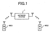
- Fig. 1 is a conceptual diagram showing the entire construction of a mobile telephone system using wireless telephones according to embodiment 1 of the invention.
- This mobile telephone system conforms to, for example, 3G (3 Generation) standards such as W-CDMA, UMTS (Universal Mobile Telecommunication System) and cdma2000, 2.5G (2.5 Generation) standards such as IS-95, or 2G (2 Generation) standards such as PDC (Personal Digital Cellular) and GSM (Global System for Mobile Communications), and is provided with a plurality of mobile telephones MS1 and MS2 (hereinafter also referred to generally as "mobile telephone MS") and a network system 1.
- 3G (3 Generation) standards such as W-CDMA, UMTS (Universal Mobile Telecommunication System) and cdma2000, 2.5G (2.5 Generation) standards such as IS-95, or 2G (2 Generation) standards such as PDC (Personal Digital Cellular) and GSM (Global System for Mobile Communications)
- MS1 and MS2 hereinafter also referred to generally as "mobile telephone MS"
- Fig. 2 is a sequence diagram for explaining call setting processing in the above-described mobile telephone system. For example, consideration will be given to a case where a call is made from one mobile telephone (hereinafter referred to as “calling mobile telephone”, as the need arises) MS1 to another mobile telephone (hereinafter referred to as “called mobile telephone”, as the need arises) MS2.
- the called mobile telephone MS2 transmits tone data previously registered therein (operating state informing data) to the calling mobile telephone MS1.
- tone data is received by the calling mobile telephone MS1.
- the calling mobile telephone MS1 on the basis of this received tone data, informs a user of the operating state of the called mobile telephone MS2.
- the above-described tone data indicates the operating state of the called mobile telephone.
- the tone data includes RBT data corresponding to a ring back tone (RBT) indicative of a calling state, and busy tone data corresponding to a busy tone indicative of a busy state.
- RBT ring back tone
- busy tone data corresponding to a busy tone indicative of a busy state.
- the calling mobile telephone MS1 can generate an RBT and a busy tone in the representation form specified by a user of the called mobile telephone MS2.
- the user of the calling mobile telephone MS1 performs a call originating manipulation (A1). Specifically, the user identifies a telephone number of the called mobile telephone MS2 by manipulating ten keys or calling the telephone number from a memory, and subsequently manipulates an originating key.
- the calling mobile telephone MS1 wirelessly transmits call setting request data in response to the above-described call originating manipulation (A2). Specifically, the calling mobile telephone MS1 wirelessly transmits to the network system 1 a call setting request signal which contains the call setting request data and identification data on the calling and called mobile telephones.
- the network system 1 when it receives the above-described call setting request signal, wirelessly transfers the above-described call setting request signal to the called mobile telephone MS2 (A3).
- the called mobile telephone MS2 when it receives the call setting request signal, wirelessly transmits a call setting accepted signal and a predetermined tone signal to the network system 1 (A4).
- the called mobile telephone MS2 transmits to the network system 1 the call setting accepted signal and the tone signal which correspond to an operating state in which the called mobile telephone MS2 is placed when it receives the above-described call setting request signal.
- the called mobile telephone MS2 transmits to the network system 1 a call setting accepted signal (ACK signal) which contains call setting accepted data (ACK data) corresponding to the idle state and identification data on the called mobile telephone MS2.
- ACK signal call setting accepted signal
- the called mobile telephone MS2 reads RBT data corresponding to the idle state from previously registered tone data, and generates a tone signal (RBT signal) containing the RBT data. Subsequently, the called mobile telephone MS2 repeatedly transmits the RBT signal to the network system 1.
- the called mobile telephone MS2 transmits to the network system 1 a call setting accepted signal (NAK signal) which contains call setting accepted data (NAK data) corresponding to the busy state and the identification data on the called mobile telephone MS2.
- NAK signal contains call setting accepted data (NAK data) corresponding to the busy state and the identification data on the called mobile telephone MS2.
- the called mobile telephone MS2 reads busy tone data corresponding to the busy state from the previously registered tone data, and generates a tone signal (busy signal) containing the tone data. Subsequently, the called mobile telephone MS2 repeatedly transmits the busy signal to the network system 1.
- the network system when it receives the call setting accepted signal and the tone signal, transfers the call setting accepted signal and the tone signal to the calling mobile telephone MS1 (A5).
- the calling mobile telephone MS1 when it receives the tone signal, generates a sound corresponding to the tone data in the tone signal (A6).
- the calling mobile telephone MS1 receives the RBT signal
- the calling mobile telephone MS1 generates an RBT.
- the calling mobile telephone MS1 receives the busy tone signal
- the calling mobile telephone MS1 generates a busy tone. In this manner, the user of the calling mobile telephone MS1 can be informed of the calling state or the busy state with the user' s original melody or sound of the called mobile telephone MS2.
- the called mobile telephone MS2 transmits the ACK signal and the RBT signal as described above, and generates a ringing tone to inform the user that the called mobile telephone MS2 has received a call (A7).
- the called mobile telephone MS2 is set off-hook by the user (A8), the called mobile telephone MS2 transmits an answer signal to the network system 1 (A9).
- the called mobile telephone MS2 stops generating the ringing tone and stops transmitting the tone signal (RBT signal) that has continued to be transmitted up to that time (A10).
- the network system 1 transmits the above-described answer signal to the calling mobile telephone MS1 (A11).
- the calling mobile telephone MS1 stops the RBT (A12).
- the setting of a call is completed and the calling mobile telephone MS1 and the called mobile telephone MS2 are brought into a conversation-possible state (A13).
- the called mobile telephone MS2 transmits the NAK signal and the busy signal as described previously. In this case, the busy signal is repeatedly transmitted. On the other hand, in this case, it is expected that the user of the calling mobile telephone MS1 will hang up. Accordingly, the called mobile telephone MS2 stops transmitting the above-described busy signal in response to the reception of a disconnection request signal (not shown).
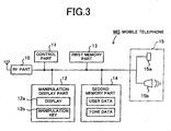
- Fig. 3 is a block diagram showing the internal construction of the mobile telephone MS.
- the mobile telephone MS is provided with a wireless (RF) part 10, a control part 11, a manipulation display part 12, a first memory part 13, a second memory part 14, and an acoustic part 15.
- the RF part 10 executes transmission/reception processing and modulation/demodulation processing of wireless signals and the like.
- the control part 11 is made of a CPU and the like, and controls the wireless (RF) part 10, the manipulation display part 12, the first and second memory parts 12 and 14, and the acoustic part 15.
- the manipulation display part 12 is provided with a display 12a and manipulating keys 12b.
- the display 12a is, for example, a liquid crystal display.
- the manipulating keys 12b includes a call originating key, a call terminating key, function keys, ten keys and the like.
- the acoustic part 15 is provided with a microphone 15a and a speaker 15b.
- the acoustic part 15 converts an analog voice signal inputted via the microphone 15a into a digital voice signal and gives the digital voice signal to the control part 11, or converted an input digital signal into an analog signal and outputs the analog signal from the speaker 15b.
- the first memory part 13 is made of, for example, a ROM (Read Only Memory), and stores computer programs and various data in a non-volatile manner.
- the second memory part 14 is made of, for example, a flash memory, and stores various data in an electrically rewritable manner. Specifically, the second memory part 14 stores user data such as destination telephone numbers and destination mail addresses as well as tone data.
- the tone data are registered in an area for tone data in the second memory part 14 of the called mobile telephone MS2, for example by tone data registration processing which will be described later.
- tone data registration processing which will be described later.
- a plurality of tone data can be registered, and each of the data is associated with an identification code.
- the user can set any one tone data to be used, and in this case, use setting data is associated with the set tone data.
- the tone data includes the RBT data and the busy tone data.
- the RBT data is made of a melody and a sound.
- the busy tone data is made of a melody.
- RBT data and busy tone data are, for example, ADPCM (Adaptive Differential Pulse Code Modulation) code data.
- ADPCM encoding is the processing of encoding data by extracting a difference between consecutive codes, and can compress the amount of data compared to simple PCM codes. Accordingly, in this embodiment 1, the storage capacity of the tone data can be made small.
- embodiment 1 since the tone data is transmitted to the calling mobile telephone, embodiment 1 also contributes to a reduction in the amount of data transmission.
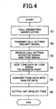
- Fig. 4 is a flowchart for explaining processing for call origination.
- the user executes a call originating manipulation (Step S1). Specifically, the user first manipulates the manipulating keys 12b to identify a designation telephone number. More specifically, the user inputs numbers by manipulating the ten keys or displays on the display 12a a registered destination telephone number registered by manipulating a function key. Subsequently, the user manipulates the call originating key. Consequently, the manipulation display part 12 gives the RF part 10 call setting request data containing the telephone number information.
- the RF part 10 generates and amplifies a call setting request signal by modulating a high frequency signal oscillated by a local oscillator (not shown) on the basis the originating data, and subsequently transmits the call setting request signal (Step S2).
- the RF part 10 restores call setting accepted data by amplifying and then demodulating the call setting accepted signal.
- the RF part 10 restores tone data by amplifying and then demodulating the tone signal.
- the RF part 10 gives these restored data to the control part 11.
- the control part 11 gives the acoustic part 15 the tone data from among these given data (Step S4).
- the acoustic part 15 decodes the tone data. Specifically, since the tone data is ADPCM-coded, the acoustic part 15 restores this ADPCM code to an original analog signal (Step S5). The acoustic part 15 gives the restored analog signal to the speaker 15b. Consequently, a sound corresponding to the tone data is outputted from the speaker 15b. In this manner, an RBT or a busy tone is generated (Step S6).
- Fig. 5 is a flowchart for explaining processing for call termination.
- the RF part 10 receives a call setting request signal from the network system 1 (Step T1)
- the RF part 10 restores call setting request data by amplifying and then demodulating the call setting request signal, and gives the call setting request data to the control part 11.
- the control part 11 when it receives the call setting request data, checks the operating state of the mobile telephone MS itself. Specifically, the control part 11 determines whether the mobile telephone MS is busy (Step T2).
- the control part 11 accesses the second memory part 14, and reads RBT data from among the tone data registered in the second memory part 14 (Step T3). In this case, if a plurality of RBT data are registered, the control part 11 reads RBT data with which use setting data is associated. Furthermore, the control part 11 gives ACK data and the above-described extracted RBT data to the RF part 10.
- the RF part 10 generates and transmits an ACK signal by modulating a high frequency signal on the basis of the ACK data, and also generates and transmits an RBT signal by modulating a high frequency signal on the basis of the RBT data (Step T4).
- the control part 11 gives the RBT data to the RF part 10 not only once but also continuously at predetermined periods. Accordingly, the RBT signal is continuously transmitted from the RF part 10.
- the control part 11 accesses the second memory part 14, and reads busy tone data from among the tone data registered in the second memory part 14 (Step T5). In this case, if a plurality of busy tone data are registered, the control part 11 reads busy tone data with which use setting data is associated. In addition, the control part 11 gives NAK data and the above-described extracted busy tone data to the RF part 10. The RF part 10 generates and transmits a NAK signal on the basis of the NAK data, and also generates and transmits a busy signal on the basis of the busy tone data (Step T6). In this case as well, the control part 11 gives the busy tone data to the RF part 10 continuously at predetermined periods, so that the busy signal is continuously transmitted from the RF part 10.
- the control part 11 after having started to give the RF part 10 the tone data, determines whether circuit disconnection has occurred or the mobile telephone MS has been set off-hook (Steps T7, T8). If the control part 11 determines that circuit disconnection has occurred or the mobile telephone MS has been set off-hook, the control part 11 stops transmitting the above-described RBT data or busy tone data to the RF part 10 (Steps T9, T10).
- Fig. 6 is a flowchart for explaining tone data registration processing.
- this tone data registration processing can be executed on only the called mobile telephone.
- the user manipulates a function key, and activates a tone data registering/changing mode as an operating mode of the mobile telephone MS (Step U1).
- the control part 11 of the mobile telephone MS displays on the display 12a a image for selecting either of the tone data registering/changing mode (Step U2).
- the control part 11 displays on the display 12a a image which urges the user to input tone data (Step U3).
- the user inputs tone data into the mobile telephone MS (Step U4).
- the user connects the mobile telephone MS to a computer such as a personal computer, and transfers melody data stored in the computer to the mobile telephone MS.
- the user connects the computer to the Internet or the like, and downloads melody data stored in a server on the Internet, and transmits the melody data from the computer to the mobile telephone MS.
- the user directly connects to the Internet from the mobile telephone MS, and downloads melody data stored in a server on the Internet.
- the user records a voice such as "please wait for a while" via the microphone 15a.
- the melody data or voice data inputted into the mobile telephone MS in this manner is given to the control part 11.
- the control part 11 after having converted this tone data into an ADPCM code, associates an identification code with the tone data and registers the tone data in the area for tone data of the second memory part 14 (Step U5). In this manner, an original tone data suited to the user's preference can be registered in the mobile telephone MS.
- the control part 11 of the mobile telephone MS displays on the display 12a an image which asks which of an RBT and a busy tone is to be changed (Step U6) .
- the control part 11 creates a list of data selected from the tone data registered in the second memory part 14, and displays on the display 12a an image which enables any data to be selected from this list (Step U7).
- the control part 11 registers the selected data in the second memory part 14 as data which is set for use (Step U8). Namely, the control part 11 stores the newly selected tone data in the second memory part 14 with the use setting data associated with the newly selected tone data. Accordingly, the subsequent RBT or busy tone is generated with a changed melody or voice.
- RBT data and busy tone data suited to the user's preference can be registered in the called mobile telephone MS2. Therefore, unlike the prior art of registering tone data in the network system 1, an RBT and a busy tone can be easily generated or changed by users themselves. Accordingly, it is possible to provide services suited to the user' preference, whereby it is possible to improve service for the user.
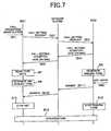
- Fig. 7 is a sequence diagram for explaining processing during call setting in a mobile telephone system according to example 1.
- the tone data registered in the called mobile telephone MS2 is transmitted to the calling mobile telephone MS1, whereby the user's original melody or sound of the called mobile telephone MS2 is generated from the calling mobile telephone MS1.
- tone data is previously registered not in the called mobile telephone MS2 but in the calling mobile telephone MS1, and in the case where the calling mobile telephone MS1 receives call setting accepted data after having originated a call, the calling mobile telephone MS1 generates an RBT or a busy tone on the above-described registered tone data. In this manner, the user of the calling mobile telephone MS1 can hear an original RBT or busy tone suited to the user's preference from his/her own mobile telephone MS. Accordingly, it is possible to improve service for the user of the calling mobile telephone MS1.
- the calling mobile telephone MS1 transmits a call setting request signal to the network system 1 (B2), and the network system 1 transmits the call setting request signal to the called mobile telephone MS2 (B3).
- the called mobile telephone MS2 when it receives the call setting request signal, does not transmit a tone signal, and transmits only a call setting accepted signal containing ACK data or NAK data to the network system 1 (B4).
- the called mobile telephone MS2 in the case where the called mobile telephone MS2 is in a conversation-possible state, the called mobile telephone MS2 generates a ringing tone (B5).
- the network system when it receives the call setting accepted signal, transmits the call setting accepted signal to the calling mobile telephone MS1 (B6).
- the RF part 10 of the calling mobile telephone MS1 receives the above-described call setting accepted signal. Namely, the calling mobile telephone MS1 receives call setting accepted data after having originated a call.
- the control part 11 of the calling mobile telephone MS1 when it receives the call setting accepted signal, reads tone data corresponding to the above-described received call setting accepted data from among the tone data previously registered in the second memory part 14 of the calling mobile telephone MS1, on the basis of the call setting accepted data in the call setting accepted signal (B7). Specifically, in the case where the ACK data is received as the call setting accepted data, the control part 11 reads RBT data from the second memory part 14. In the case where the NAK is received, the control part 11 reads busy tone data from the second memory part 14. In this case, if a plurality of RBT data or busy tone data are registered, the control part 11, like in embodiment 1, selects RBT data or busy tone data with which use setting data is associated.
- the control part 11 gives the above-described extracted RBT data or busy tone data to the acoustic part 15.
- the acoustic part 15 converts the RBT data or busy tone data into an analog signal, and gives the analog signal to the speaker 15b. Consequently, an RBT or a busy tone corresponding to the above-described RBT data or busy tone data is outputted from the speaker 15b (B8).
- the control part 11 since the control part 11 repeatedly gives the RBT data or the busy tone data to the acoustic part 15, the RBT or the busy tone is repeatedly outputted. In this manner, the calling mobile telephone MS1 informs the user of a tone corresponding to the operating state of the called mobile telephone MS2.
- the called mobile telephone MS2 After the call setting accepted signal containing the ACK data has been transmitted, if an off-hook manipulation is performed on the called mobile telephone MS2 (B9), the called mobile telephone MS2 stops the ringing tone (B10), and transmits an answer signal to the calling mobile telephone MS1 via the network system 1 (B11, B12). In response to the reception of this answer signal, the control part 11 of the calling mobile telephone MS1 disables the processing of giving the RBT data to the acoustic part 15 (B12). Therefore, the RBT comes to a stop. Subsequently, a conversation is initiated (B13)
- tone data need not be previously registered in the called mobile telephone MS2, whereby even if the user is to call a mobile telephone already shipped to the market, RBT and a busy tone suited to the user's preference can be provided to the user. Accordingly, example 1 can be put to practical use more easily than embodiment 1. In addition, since a tone signal need not be transmitted, it is possible to reduce traffic.
- Fig. 8 is a block diagram showing the internal construction of the mobile telephone MS according to embodiment 2.
- the same reference numerals are used to denote the same functional parts as those shown in Fig. 3 .
- embodiment 2 has the advantage that the mobile telephone MS does not need a storage area dedicated to tone data.
- ringing tone data in addition to user data, is stored in the second memory part 14 of the mobile telephone MS according to this embodiment 2.
- the ringing tone data is data on a ringing tone to be generated when an incoming call is received, and, for example, is stored previously or is stored by being downloaded from the Internet.
- the ringing tone data is associated with either of RBT or busy tone. That is to say, the ringing tone data is associated with the operating state of the mobile telephone MS.
- tone data is transmitted from the called mobile telephone MS2 to the calling mobile telephone MS1 as in embodiment 1
- the control part 11 of the called mobile telephone MS2 reads ringing tone data from the second memory part 14, and generates a ringing tone corresponding to the ringing tone data.
- the control part 11 reads ringing tone data corresponding to an RBT from the second memory part 14, and gives the ringing tone data to the RF part 10 as RBT data. Consequently, the RF part 10 generates a tone signal containing the RBT data, and transmits the tone signal to the calling mobile telephone MS1 via the network system 1.
- the calling mobile telephone MS1 generates an RBT corresponding to the RBT data (ringing tone data) in this received tone signal.
- the control part 11 of the called mobile telephone MS2 reads ringing tone data associated with a busy tone from the second memory part 14, and gives the ringing tone data to the RF part 10 as busy tone data. Consequently, the RF part 10 generates a tone signal containing the busy tone data, and transmits the tone signal to the calling mobile telephone MS1 via the network system 1.
- the calling mobile telephone MS1 generates a busy tone corresponding to the busy tone data (ringing tone data) in this received tone signal.
- a case where a tone is generated on the basis of tone data registered in the calling mobile telephone MS1 as in the above-described example 1 will be described below by way of example.
- the calling mobile telephone MS1 receives call setting accepted data from the called mobile telephone MS2 via the network system 1
- the calling mobile telephone MS1 reads ringing tone data corresponding to the call setting accepted data from the second memory part 14 as tone data.
- the control part 11 of the calling mobile telephone MS1 reads ringing tone data associated with an RBT from the second memory part 14.
- the control part 11 reads ringing tone data associated with a busy tone from the second memory part 14.
- the control part 11 gives this read ringing tone data to the acoustic part 15. Consequently, a ringing tone corresponding to the above-described ringing tone data is generated from the speaker 15b of the acoustic part 15.
- tone data already registered in the mobile telephone MS is utilized as tone data, a storage area dedicated to tone data can be eliminated.
- work for registering tone data can be omitted, it is possible to save the user's trouble.
- Fig. 9 is a schematic block diagram showing the construction of the network system 1 according to example 2.
- tone data is registered in the mobile telephone MS.
- the reason for this is to enable the user to newly create or change tone data.
- a place in which to register tone data need not necessarily be the mobile telephone MS.
- registering/changing processing for tone data is made executable exclusively on the side of the mobile telephone MS, and the network system 1 is made a place in which to register the tone data.
- the network system 1 is provided with a plurality of base stations (BS: Base Station) 20 which performs wireless communication with the mobile telephone MS, a mobile control station (MCS: Mobile Control Station) 21 which controls this plurality of base stations 20, and an automobile switching center (AMC: Automobile Switching Center) 22 which is connected to the mobile control station 21.
- the automobile switching center 22 is connected to another automobile switching center and another communication network, and executes circuit routing processing.
- the network system 1 is also provided with a tone data storage device 23.
- the tone data storage device 23 stores tone data transmitted from the mobile telephone MS. More specifically, the tone data storage device 23 is connected to the automobile switching center 22.
- the tone data storage device 23 corresponds to, for example, a part of the storage area of a home memory which stores detailed information on the user of the mobile telephone MS. Control of writing and reading of tone data to and from the tone data storage device 23 is performed by the automobile switching center 22.
- Fig. 10 is a flowchart for explaining tone data registering/changing processing in the mobile telephone MS.
- This tone data registering/changing processing can be executed from either of the calling mobile telephone MS1 and the called mobile telephone MS2.
- the user of the calling mobile telephone MS1 or the called mobile telephone MS2 manipulates a function key to set the operating mode of the mobile telephone to a tone data registering/changing mode (Step V1).
- Step V2 the control part 11 displays a tone data inputting image on the display 12a (Step V3), and when tone data is inputted (Step V4), the control part 11 gives the RF part 10 the tone data and identification data on the mobile telephone MS. Consequently, the RF part 10 generates a registration request signal containing the above-described tone data and mobile telephone identification data and transmits the registration request signal to the network system 1 (Step V5). In this manner, the user can request the network system 1 to register the tone data.
- the control part 11 displays on the display 12a an image for selecting either of an RBT and a busy tone (Step V6).
- the control part 11 gives list request data to the RF part 10 to acquire a list of the selected data.
- the RF part 10 transmits a list request signal containing the list request data to the network system 1 (Step V7) .
- the control part 11 receives the list of registered tone data from the network system 1 (Step V8), the network system 1 displays the list on the display 12a (Step V9).
- the control part 11 gives the RF part 10 change request data containing an identification code for identifying the selected data, and causes the RF part 10 to transmit a change request signal containing the above-described change request data to the network system 1 (Step V11). In this manner, the user can request the network system 1 to change tone data to be used.
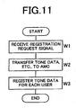
- Fig. 11 is a flowchart for explaining the tone data registering/changing processing in the network system 1.
- the base station 20 of the network system 1 receives the registration request signal transmitted from the mobile telephone MS (Step W1)
- the base station 20 restores the tone data and the mobile telephone identification data from the registration request signal, and transfers each of the data to the automobile switching center 22 via the mobile control station 21 (Step W2).
- the automobile switching center 22 when it receives each of the above-described data, stores the tone data into the tone data storage device 23 by using the mobile telephone identification data as an index (Step W3). Namely, the automobile switching center 22 registers tone data for each user. In other words, the automobile switching center 22 registers the tone data associated with the mobile telephone MS. In this manner, the registration of the tone data is completed.
- Fig. 12 is a flowchart for explaining the tone data changing processing in the network system 1.
- the base station 20 of the network system 1 receives the registration request signal transmitted from the mobile telephone MS (Step X1)
- the base station 20 restores the list request data from the list request signal, and transfers the list request data to the automobile switching center 23 via the mobile control station 21 (Step X2).
- the automobile switching center 22, when it receives this list request data reads from the tone data storage device 23 a list of tone data corresponding to the mobile telephone MS which has transmitted the list request data, and works the list of tone data into list data, and subsequently transmits the list data to the mobile telephone MS via the mobile control station 21 and the base station 20 (Step X3).
- Step X4 when the change request signal transmitted from the mobile telephone MS is received by the base station 20 (Step X4), the base station 20 restores the change request data from the change request signal, and transfers the change request data to the automobile switching center 22 via the mobile control station 21 (Step X5).
- Fig. 13 is a sequence diagram for explaining call setting processing according to this example 2.
- the calling mobile telephone MS1 when a call originating manipulation is performed (C1), transmits a call setting request signal to the network system 1 (C2), and the network system 1 transmits the call setting request signal to the called mobile telephone MS2 (C3).
- the called mobile telephone MS2 when it receives the above-described call setting request signal, transmits a call setting accepted signal (an ACK signal or an NAK signal) to the network system 1 (C4).
- the network system 1 when it receives the above-described call setting accepted signal, transmits to the calling mobile telephone MS1 tone data corresponding to the operating state of the called mobile telephone MS2 from among registered tone data associated with the calling mobile telephone MS1 or the called mobile telephone MS2.
- the network system 1 when it receives the above-described call setting accepted data, selects tone data corresponding to the user (C5), and transmits the tone data to the calling mobile telephone MS1 (C6).
- the base station 20 of the network system 1 receives the call setting request signal transmitted from the calling mobile telephone MS1, the base station 20 extracts identification data on the calling mobile telephone MS1 and the called mobile telephone MS2 from the call setting request signal, and transfers the identification data to the automobile switching center 22 via the mobile control station 21 (Step W2).
- the automobile switching center 22 temporarily stores these identification data.
- the automobile switching center 22 receives the call setting accepted data from the base station 20 which has received the call setting accepted signal from the called mobile telephone MS2, the automobile switching center 22 refers to the above-described retained identification data, and reads tone data corresponding to the identification data from the tone data storage device 23.
- the automobile switching center 22 reads the registered tone data corresponding to the mobile telephone MS. In this case, when a plurality of tone data are registered, the automobile switching center 22 reads tone data which is set for use.
- the automobile switching center 22 gives priority to an improvement in service for the user on the call originating side, and reads tone data corresponding to the calling mobile telephone MS1.
- the automobile switching center 22 may also read tone data corresponding to the called mobile telephone MS2.
- the automobile switching center 22 when it reads the tone data in the above-described manner, transmits the above-described call setting accepted data and the above-described extracted tone data to the base station 20 communicating with the mobile telephone MS via the mobile control station 21.
- the base station 20 generates a call setting accepted signal containing the call setting accepted data and a tone signal containing the tone data to the calling mobile telephone MS1 (C6).
- the network system 1 transmits the call setting accepted signal only once, but continuously transmits the tone signal.
- calling mobile telephone MS1 when it receives the call setting accepted signal and the tone signal, generates an RBT or a busy tone corresponding to the tone data contained in the tone signal (C7). As described above, the tone signal is continuously transmitted. In this manner, it is possible to continuously generate the RBT or the busy tone registered by the user of the calling mobile telephone MS1 or the called mobile telephone MS2.
- the called mobile telephone MS2 makes a ringing tone (C8), and when the called mobile telephone MS2 is set off-hook by the user (C9), the called mobile telephone MS2 transmits an answer signal to the network system 1 (C10), and stops the ringing tone (C11).
- the network system 1 when it receives the answer signal, stops the transmission of the tone data by the automobile switching center 22 (C12). Namely, the network system 1 stops transmitting the tone signal. Subsequently, the network system 1 transmits the above-described received answer signal to the calling mobile telephone MS1 (C13).
- the calling mobile telephone MS1 which has received this answer signal stops the RBT (C14), and starts conversation with the called mobile telephone MS2 (C15).
- tone data can be generated or changed in the mobile telephone MS, it is possible to generate an original RBT data and busy tone suited to the user's preference.
- the tone data required to generate the above-described RBT and the like are registered in the network system 1, the tone data can be collectively managed in the network system 1.
- the mobile telephone MS does not need to store tone data unlike in the above-described embodiment 1 and example 1, the storage area of the mobile telephone MS can be release for another use.
- Fig. 14 is a sequence diagram for explaining call setting processing according to example 3.
- the "calling state” and the "busy state” are adopted as the operating states of the called mobile telephone MS2.
- a power-off and existing-out-of-service-area state is adopted as one of the operating states of the called mobile telephone MS2
- this operating state is added is not applied to any embodiment or example in which operating state informing data is transmitted from the called mobile telephone MS2 like in embodiment 1.
- the called mobile telephone MS2 is incapable of transmitting operating state informing data.
- intercept tone A sound to be generated in the calling mobile telephone MS1 in the case where the called mobile telephone MS2 is in a power-off state and exists out of a service area is called intercept tone.
- a representative example of the intercept tone is the voice "the telephone you calls is turned off or is in a place radio waves do not reach”. Namely, the intercept tone is generated during the state in which reception of data is impossible.
- the data of this intercept tone is registered as tone data together with RBT data and busy tone data.
- a registration place is the second memory part 14 in the calling mobile telephone MS1 or the tone data storage device 23 of the network system 1.
- the calling mobile telephone MS1 wirelessly transmits a call setting request signal to the network system 1 (D2).
- the network system 1 transmits this call setting request signal to the called mobile telephone MS2 (D3).
- a call setting accepted signal is not returned to the network system 1 from the called mobile telephone MS2.
- the network system 1 repeatedly transmits the call setting accepted signal to the called mobile telephone MS2 (D3), and determines whether the network system 1 has received a call setting accepted signal within a predetermined time (D4).
- the power of the called mobile telephone MS2 can be regarded as being off, or the called mobile telephone MS2 can be regarded as existing out of the service area, so that the network system 1 transmits call setting accepted data indicative of an intercept state to the calling mobile telephone MS1.
- tone data are registered in the calling mobile telephone MS1 and to the case where tone data are registered in the network system 1.
- the network system 1 transmits only the above-described call setting accepted data to the calling mobile telephone MS1 (D5).
- the calling mobile telephone MS1 when it receives the above-described call setting accepted data, reads intercept tone data corresponding to the above-described call setting accepted data from among the tone data registered in the second memory part 14 (D6), and generates an intercept tone corresponding to the intercept tone data from the speaker 15b (D7).
- the network system 1 transmits both of the above-described call setting accepted data and tone data to the calling mobile telephone MS1 (D5, D8).
- the automobile switching center 22 of the network system 1 accesses the tone data storage device 23, and reads intercept tone data from among the registered tone data associated with the calling mobile telephone MS1 or the called mobile telephone MS2. Then, the automobile switching center 22 transmits this read intercept tone data to the calling mobile telephone MS1 as tone data.
- the calling mobile telephone MS1 when it receives the above-described call setting accepted data and intercept tone data, generates a sound corresponding to the received intercept tone data from the speaker 15b (D7).
- the "power-off and existing-out-of-service-area state” is adopted as one of the operating states of the called mobile telephone. Accordingly, it is possible to improve service for the user to a further extent.
- Fig. 15 is a block diagram showing the internal construction of the mobile telephone MS according to example 4.
- the same reference numerals are used to denote the same functional parts as those shown in Fig. 3 .
- tone data has been described as the operating state informing data by way of example.
- character data and image data are adopted as the operating state informing data.
- image represents a concept including still images and moving images.
- tone data and character data as well as image data are stored in the second memory part 14 of the mobile telephone MS.
- Each of the character data and the image data is data indicative of a calling state, a busy state or a data-reception-impossible state. Namely, character data indicative of a calling state, character data indicative of a busy state, and character data indicative of a data-reception-impossible state are stored in the second memory part 14. Further, image data indicative of a calling state, image data indicative of a busy state, and image data indicative of a data-reception-impossible state are registered in the second memory part 14.
- the character data and/or the image data are read from the second memory part 14.
- the character data and/or the image data are read together with tone data corresponding to the same operating state.
- tone data For example, in the case where the called mobile telephone MS2 is in a communication-possible state, RBT data and the character data and/the image data indicative of a calling state are read from the second memory part 14.
- busy tone data and the character data and/the image data indicative of an idle state are read from the second memory part 14.
- intercept tone data and the character data and/or the image data are read from the second memory part 14. Accordingly, the calling mobile telephone MS1 outputs an RBT, a busy tone or an intercept tone from the speaker 15b, and also displays on the display 12a a character or an image corresponding to the operating state of the called mobile telephone MS2.
- the user of the calling mobile telephone MS1 is formed of the operating state of the called mobile telephone MS2 by using not only tones such as an RBT, a busy tone and an intercept tone but also a character and/or an image. Accordingly, the user's originality can be made far higher, and since the operating state can be represented by sound and visual information, informing performance can also be made far higher.
Landscapes
- Engineering & Computer Science (AREA)
- Signal Processing (AREA)
- Computer Networks & Wireless Communication (AREA)
- Human Computer Interaction (AREA)
- Mobile Radio Communication Systems (AREA)
- Telephonic Communication Services (AREA)
- Telephone Function (AREA)
Claims (8)
- Téléphone sans fil comprenant :- un récepteur (10) destiné à recevoir des données de demande d'établissement d'appel provenant d'un téléphone appelant ;- un registre (14) dans lequel sont préalablement enregistrées des données d'information sur l'état de fonctionnement indiquant les états de fonctionnement ;- un lecteur de données (11) destiné, dans le cas où les données de demande d'établissement d'appel sont reçues par le récepteur (10), à lire les données d'information sur l'état de fonctionnement correspondant à un état de fonctionnement du téléphone sans fil lorsque le récepteur (10) reçoit les données de demande d'établissement d'appel à partir des données d'information sur l'état de fonctionnement enregistrées dans le registre (14) ; et- un transmetteur (10) destiné à effectuer une transmission sans fil des données d'information sur l'état de fonctionnement lues au téléphone appelant (MS1) ;- et dans lequel les données d'information sur l'état de fonctionnement indiquent l'un des états parmi un état d'appel, un état occupé et un état indiquant l'impossibilité de recevoir des données, enregistré par un utilisateur avant la connexion au téléphone appelant, et- dans lequel le téléphone sans fil est en outre conçu pour lire les données d'information sur l'état de fonctionnement en réponse aux données de demande d'établissement d'appel reçues.
- Téléphone selon la revendication 1,
comprenant en outre une partie entrée des données destinée à entrer les données d'information sur l'état de fonctionnement et un contrôleur d'enregistrement (11) destiné à enregistrer dans le registre (14) les données d'information sur l'état de fonctionnement entrées par la partie entrée des données. - Téléphone selon la revendication 1 ou la revendication 2,
dans lequel les données d'information sur l'état de fonctionnement sont des données de tonalité de rappel représentatives de l'état d'appel, des données de tonalité occupée représentatives de l'état occupé ou des données de tonalité d'interception représentatives de l'état indiquant l'impossibilité de recevoir des données. - Téléphone selon l'une quelconque des revendications 1 à 3,
dans lequel les données d'information sur l'état de fonctionnement comprennent des données de caractères ou des données d'image respectivement représentatives de l'état d'appel, de l'état occupé, ou de l'état indiquant l'impossibilité de recevoir des données. - Téléphone selon l'une quelconque des revendications 1 à 4,
dans lequel les données d'information sur l'état de fonctionnement comprennent des données de sonnerie associées à l'état de fonctionnement. - Système de téléphone sans fil comprenant un système de réseau (1), un téléphone sans fil appelant (MS1) et un téléphone sans fil appelé (MS2) ayant un dispositif de communication destiné à communiquer dans le système de réseau (1), dans lequel le système de réseau (1) comprend :- un registre destiné à enregistrer les données d'information sur l'état de fonctionnement relatives à un état de fonctionnement du téléphone sans fil appelé (MS2) et qui sont associées au téléphone sans fil appelant (MS1) et au téléphone sans fil appelé (MS2) et associées au téléphone sans fil appelant (MS1), en réponse à un signal de demande transmis par le téléphone sans fil appelé (MS2).- un contrôleur pour le dispositif de communication destiné à recevoir un signal accepté d'établissement d'appel provenant du téléphone sans fil appelé (MS2), à choisir les données d'information sur l'état de fonctionnement correspondant au signal accepté d'établissement d'appel et à transmettre les données d'information sur l'état de fonctionnement au téléphone sans fil appelant (MS1), dans le cas où le téléphone sans fil appelant (MS1) appelle le téléphone sans fil appelé (MS2),dans lequel le téléphone sans fil appelant (MS1) comprend :- un récepteur (10) destiné à recevoir les données d'information sur l'état de fonctionnement transmises en provenance du système de réseau (1), dans lequel les données d'information sur l'état de fonctionnement transmises indiquent l'un des états parmi un état d'appel, un état occupé et un état indiquant l'impossibilité de recevoir des données, enregistré par un utilisateur avant la connexion au téléphone sans fil appelé (MS2), et- une partie informative (12a, 15) destinée à fournir des informations sur un état de fonctionnement du téléphone sans fil appelé (MS2) d'après les données d'information sur l'état de fonctionnement.
- Système selon la revendication 6,
dans lequel les données d'information sur l'état de fonctionnement sont des données de tonalité de rappel représentatives de l'état d'appel, des données de tonalité occupée représentatives de l'état occupé ou des données de tonalité d'interception représentatives de l'état indiquant l'impossibilité de recevoir des données, la partie informative (15) sur l'état de fonctionnement générant respectivement une tonalité de rappel, une tonalité occupée ou une tonalité d'interception. - Système selon la revendication 6 ou la revendication 7,
dans lequel les données d'information sur l'état de fonctionnement comprennent des données de caractères ou des données d'image respectivement représentatives de l'état d'appel, de l'état occupé, ou de l'état indiquant l'impossibilité de recevoir des données, la partie informative (12a) sur l'état de fonctionnement affichant sur un écran un caractère correspondant aux données de caractères ou une image correspondant aux données d'image.
Priority Applications (1)
| Application Number | Priority Date | Filing Date | Title |
|---|---|---|---|
| EP09167720A EP2120489A1 (fr) | 2001-07-13 | 2001-07-13 | Téléphone sans fil et système téléphonique sans fil |
Applications Claiming Priority (1)
| Application Number | Priority Date | Filing Date | Title |
|---|---|---|---|
| PCT/JP2001/006099 WO2003009632A1 (fr) | 2001-07-13 | 2001-07-13 | Telephone sans fil et systeme telephonique sans fil |
Related Child Applications (1)
| Application Number | Title | Priority Date | Filing Date |
|---|---|---|---|
| EP09167720A Division EP2120489A1 (fr) | 2001-07-13 | 2001-07-13 | Téléphone sans fil et système téléphonique sans fil |
Publications (3)
| Publication Number | Publication Date |
|---|---|
| EP1408711A1 EP1408711A1 (fr) | 2004-04-14 |
| EP1408711A4 EP1408711A4 (fr) | 2006-06-07 |
| EP1408711B1 true EP1408711B1 (fr) | 2009-12-23 |
Family
ID=11737546
Family Applications (2)
| Application Number | Title | Priority Date | Filing Date |
|---|---|---|---|
| EP01948011A Expired - Lifetime EP1408711B1 (fr) | 2001-07-13 | 2001-07-13 | Telephone sans fil et systeme telephonique sans fil |
| EP09167720A Withdrawn EP2120489A1 (fr) | 2001-07-13 | 2001-07-13 | Téléphone sans fil et système téléphonique sans fil |
Family Applications After (1)
| Application Number | Title | Priority Date | Filing Date |
|---|---|---|---|
| EP09167720A Withdrawn EP2120489A1 (fr) | 2001-07-13 | 2001-07-13 | Téléphone sans fil et système téléphonique sans fil |
Country Status (6)
| Country | Link |
|---|---|
| US (1) | US7123903B2 (fr) |
| EP (2) | EP1408711B1 (fr) |
| JP (1) | JP4225060B2 (fr) |
| CN (1) | CN1258949C (fr) |
| DE (1) | DE60140901D1 (fr) |
| WO (1) | WO2003009632A1 (fr) |
Families Citing this family (19)
| Publication number | Priority date | Publication date | Assignee | Title |
|---|---|---|---|---|
| US20040001518A1 (en) * | 2002-06-28 | 2004-01-01 | Siemens Information | System and method for emulating ringback transparently |
| AU2003303785A1 (en) * | 2003-01-17 | 2004-08-13 | Nokia Corporation | Musical audible alert termination |
| CN1310530C (zh) * | 2003-05-26 | 2007-04-11 | 华为技术有限公司 | 一种实现回铃音业务的方法 |
| US7340049B2 (en) * | 2003-10-10 | 2008-03-04 | Lucent Technologies Inc. | Feedback to calling communication device on call connected with intelligent network signaling |
| US8644886B1 (en) | 2004-03-15 | 2014-02-04 | Avaya Inc. | Ring-tone messaging service |
| US8880035B1 (en) * | 2004-03-31 | 2014-11-04 | Avaya Inc. | User customizable reverse ring tone |
| US8375119B2 (en) | 2004-07-27 | 2013-02-12 | At&T Intellectual Property I, L. P. | Methods, systems, devices, and products for providing alerts for communications |
| US7889853B2 (en) * | 2004-07-27 | 2011-02-15 | At&T Intellectual Property I, L.P. | Methods, systems, devices, and products for providing ring backs |
| US20060030316A1 (en) * | 2004-08-05 | 2006-02-09 | Ixi Mobile (R&D) Ltd. | Advance viewing of subscriber profile in a communication system |
| US7277691B1 (en) * | 2005-03-24 | 2007-10-02 | Sprint Spectrum L.P. | Method and system for management of call tones |
| US7493125B2 (en) * | 2005-06-10 | 2009-02-17 | Alcatel-Lucent Usa Inc. | Methods and apparatus for providing location enabled ring tones or ring backs |
| CN1852362B (zh) * | 2005-08-15 | 2012-05-23 | 华为技术有限公司 | 被叫向主叫提供指示信息的方法 |
| CN100499707C (zh) * | 2005-08-19 | 2009-06-10 | 华为技术有限公司 | 一种提供个性化信息的装置和方法 |
| WO2007068207A1 (fr) * | 2005-12-17 | 2007-06-21 | Huawei Technologies Co., Ltd. | Procede, systeme et terminal destines a fournir un signal de rappel en temps reel |
| CN1964396B (zh) * | 2006-09-30 | 2011-07-06 | 华为技术有限公司 | 实现彩铃复制的方法、系统及装置 |
| KR101294293B1 (ko) * | 2006-10-27 | 2013-08-08 | 엘지전자 주식회사 | 통신 연결 제어 방법 및 이를 구현하는 이동통신 단말기 |
| US20100232309A1 (en) * | 2009-03-13 | 2010-09-16 | Qualcomm Incorporated | Methods and systems for dynamic call blocking in wimax idle mode |
| JP2010251884A (ja) * | 2009-04-13 | 2010-11-04 | Fumiichiro Noma | サーバ装置、およびプログラム |
| US9660793B2 (en) * | 2015-06-26 | 2017-05-23 | Intel Corporation | Leveraging full duplex for rate adaptation in wireless LANs |
Family Cites Families (19)
| Publication number | Priority date | Publication date | Assignee | Title |
|---|---|---|---|---|
| JP2685525B2 (ja) * | 1988-09-02 | 1997-12-03 | 株式会社日立製作所 | 移動無線電話方式 |
| JPH0459648A (ja) | 1990-06-27 | 1992-02-26 | Tsutsunaka Plast Ind Co Ltd | 無機成形体用組成物 |
| JP2525477Y2 (ja) * | 1990-09-29 | 1997-02-12 | 株式会社東芝 | 呼出し機能付き無線電話装置 |
| JP3170167B2 (ja) | 1995-01-11 | 2001-05-28 | 株式会社東芝 | コードレス電話装置 |
| JPH0984140A (ja) * | 1995-09-14 | 1997-03-28 | Nec Corp | 無線通信機 |
| US6018671A (en) * | 1995-12-29 | 2000-01-25 | Motorola, Inc. | Silent call accept |
| JP3268232B2 (ja) | 1997-05-12 | 2002-03-25 | 日本ビクター株式会社 | 構内電話システム |
| SE512079C2 (sv) * | 1997-10-15 | 2000-01-24 | Ericsson Telefon Ab L M | Metod för tillhandahållande av en anropad abonnents status i ett mobilt telefonsystem |
| JPH11313177A (ja) * | 1998-02-24 | 1999-11-09 | Toshiba Corp | マルチメディア情報通信システム |
| JPH11252651A (ja) * | 1998-02-27 | 1999-09-17 | Toshiba Corp | 移動通信システムとその移動端末装置および制御装置 |
| WO2000006596A2 (fr) | 1998-07-28 | 2000-02-10 | Us Health | HYBRIDES D'INTERFERON- alpha |
| JP3490898B2 (ja) | 1998-07-29 | 2004-01-26 | シャープ株式会社 | 携帯電話端末 |
| US6154644A (en) * | 1998-09-08 | 2000-11-28 | Telefonaktiebolaget L M Ericsson | System and method of implementing an interactive callback feature in a radio telecommunications network |
| JP2000286932A (ja) * | 1999-03-31 | 2000-10-13 | Kokusai Electric Co Ltd | 移動端末 |
| KR100378953B1 (ko) * | 1999-04-14 | 2003-04-08 | 주식회사 아이디어파크 | 호출음과 화중음 선택형 통신기기 |
| EP1157531B1 (fr) | 1999-07-19 | 2004-07-28 | Ringfree Co., Ltd. | Procede et dispositif de production d'une tonalite de retour d'appel d'informations commerciales vocales/textuelles/images pendant une attente de communication |
| KR100292089B1 (ko) * | 1999-10-06 | 2001-06-01 | 박종현 | 유,무선 통신망의 착신교환시스템에서 착신자가 선택한 링백톤의 대체음 발생방법 및 장치 |
| US7489768B1 (en) * | 2000-06-01 | 2009-02-10 | Jonathan Strietzel | Method and apparatus for telecommunications advertising |
| US6741678B2 (en) * | 2001-05-31 | 2004-05-25 | Lucent Technologies Inc. | Method and system for sending a data response from a called phone to a calling phone |
-
2001
- 2001-07-13 EP EP01948011A patent/EP1408711B1/fr not_active Expired - Lifetime
- 2001-07-13 WO PCT/JP2001/006099 patent/WO2003009632A1/fr not_active Ceased
- 2001-07-13 DE DE60140901T patent/DE60140901D1/de not_active Expired - Lifetime
- 2001-07-13 JP JP2002589147A patent/JP4225060B2/ja not_active Expired - Fee Related
- 2001-07-13 EP EP09167720A patent/EP2120489A1/fr not_active Withdrawn
- 2001-07-13 US US10/344,899 patent/US7123903B2/en not_active Expired - Fee Related
- 2001-07-13 CN CNB018148786A patent/CN1258949C/zh not_active Expired - Fee Related
Also Published As
| Publication number | Publication date |
|---|---|
| CN1258949C (zh) | 2006-06-07 |
| EP2120489A1 (fr) | 2009-11-18 |
| JP4225060B2 (ja) | 2009-02-18 |
| US20040102163A1 (en) | 2004-05-27 |
| EP1408711A1 (fr) | 2004-04-14 |
| CN1488229A (zh) | 2004-04-07 |
| JPWO2003009632A1 (ja) | 2004-11-11 |
| WO2003009632A1 (fr) | 2003-01-30 |
| US7123903B2 (en) | 2006-10-17 |
| DE60140901D1 (de) | 2010-02-04 |
| EP1408711A4 (fr) | 2006-06-07 |
Similar Documents
| Publication | Publication Date | Title |
|---|---|---|
| EP2120489A1 (fr) | Téléphone sans fil et système téléphonique sans fil | |
| KR100732002B1 (ko) | 개인화 수단을 지니는 통신 단말기 | |
| KR100651388B1 (ko) | 이동통신 단말기에서 착신알림 설정방법 | |
| US6907256B2 (en) | Mobile terminal with an automatic translation function | |
| US7596374B2 (en) | Data backup system and method for mobile communication terminal, mobile communication terminal and backup device used for same, and backup data transmission method | |
| US20050065791A1 (en) | Apparatus and method for voice recognition and displaying of characters in mobile telecommunication system | |
| US20020090068A1 (en) | Method of transmitting and receiving image files in mobile phone | |
| JP2002247144A (ja) | 携帯電話装置およびその着信方法 | |
| KR100703507B1 (ko) | 이동통신 시스템에서의 발신자 식별정보 기능 서비스 방법 | |
| KR20010046956A (ko) | 이동 무선 단말기의 발신측 사용자 알림 방법 | |
| KR100506246B1 (ko) | 통신단말기의발신자이름을포함한발신자정보표시방법 | |
| KR20000073341A (ko) | 이미지 수신 가능한 단말기, 이를 이용한 이미지 전송 서비스시스템 및 그 방법 | |
| KR20060071241A (ko) | 단문메시지 필터링 장치 및 그 방법과 그를 이용한무선통신단말기 및 그 방법 | |
| KR100977993B1 (ko) | 이동단말기의 수신거부 방법 | |
| KR100413625B1 (ko) | 착신 제한이 가능한 이동통신 단말기 및 착신 제한방법과, 착신 제한 서비스를 제공하는 이동통신 시스템 및착신 제한 서비스 제공 방법 | |
| KR100539872B1 (ko) | 이동통신단말시스템의 단문메시지 서비스 방법 | |
| KR100986264B1 (ko) | 이동단말기에 저장된 멀티미디어 데이터 전송 방법 | |
| KR20020069987A (ko) | 단문 메시지 서비스를 이용하여 개인 비서 기능을 갖는이동 통신 단말기 및 그 구현 방법 | |
| KR100971621B1 (ko) | 휴대용 무선단말기의 단문 메세지 전송 방법 및 장치 | |
| JPH1146240A (ja) | 音声通知機能付き携帯通信端末 | |
| WO2007032620A1 (fr) | Procede et appareil pour ameliorer les appels dans un terminal de communications mobiles | |
| KR101020371B1 (ko) | 이동 통신 단말기의 메시지 송수신 방법 | |
| KR20030013630A (ko) | 이동통신 단말기에서의 선택적 단문 메시지 수신방법 | |
| KR20050095251A (ko) | 이동통신 단말기의 음성통화 중 멀티미디어 데이터 송수신방법 | |
| JP2001268209A (ja) | 電話装置、電話装置の発信方法及び記録媒体 |
Legal Events
| Date | Code | Title | Description |
|---|---|---|---|
| PUAI | Public reference made under article 153(3) epc to a published international application that has entered the european phase |
Free format text: ORIGINAL CODE: 0009012 |
|
| 17P | Request for examination filed |
Effective date: 20030227 |
|
| AK | Designated contracting states |
Kind code of ref document: A1 Designated state(s): AT BE CH CY DE DK ES FI FR GB GR IE IT LI LU MC NL PT SE TR |
|
| RAP1 | Party data changed (applicant data changed or rights of an application transferred) |
Owner name: MITSUBISHI DENKI KABUSHIKI KAISHA |
|
| A4 | Supplementary search report drawn up and despatched |
Effective date: 20060502 |
|
| 17Q | First examination report despatched |
Effective date: 20070417 |
|
| RIC1 | Information provided on ipc code assigned before grant |
Ipc: H04W 4/16 20090101AFI20090211BHEP |
|
| GRAP | Despatch of communication of intention to grant a patent |
Free format text: ORIGINAL CODE: EPIDOSNIGR1 |
|
| GRAS | Grant fee paid |
Free format text: ORIGINAL CODE: EPIDOSNIGR3 |
|
| RIN1 | Information on inventor provided before grant (corrected) |
Inventor name: SEKI, SHUICHI,MITSUBISHI DENKI K.K. |
|
| GRAA | (expected) grant |
Free format text: ORIGINAL CODE: 0009210 |
|
| AK | Designated contracting states |
Kind code of ref document: B1 Designated state(s): DE FR GB |
|
| REG | Reference to a national code |
Ref country code: GB Ref legal event code: FG4D |
|
| REF | Corresponds to: |
Ref document number: 60140901 Country of ref document: DE Date of ref document: 20100204 Kind code of ref document: P |
|
| REG | Reference to a national code |
Ref country code: GB Ref legal event code: S27 Free format text: APPLICATION FILED; APPLICATION TO AMEND SPECIFICATION UNDER SECTION 27 FILED ON 30 MARCH 2010 |
|
| REG | Reference to a national code |
Ref country code: GB Ref legal event code: S27 Free format text: APPLICATION OPEN FOR OPPOSITION; PATENTS FORM 15 GIVING THE COMPTROLLER NOTICE OF OPPOSITION TO THE AMENDMENTS. YOU ALSO NEED TO FILE TWO COPIES OF A STATEMENT SETTING OUR FULLY THE FACTS OF YOUR CASE AND THE RELIEF THAT YOU ARE SEEKINGFOR A COPY OF THESE AMENDMENTS, PHONE LITIGATION SECTION (01633 814376) |
|
| PLBE | No opposition filed within time limit |
Free format text: ORIGINAL CODE: 0009261 |
|
| STAA | Information on the status of an ep patent application or granted ep patent |
Free format text: STATUS: NO OPPOSITION FILED WITHIN TIME LIMIT |
|
| 26N | No opposition filed |
Effective date: 20100924 |
|
| REG | Reference to a national code |
Ref country code: FR Ref legal event code: TP |
|
| REG | Reference to a national code |
Ref country code: GB Ref legal event code: 732E Free format text: REGISTERED BETWEEN 20110707 AND 20110713 |
|
| REG | Reference to a national code |
Ref country code: GB Ref legal event code: S27 Free format text: SPECIFICATION AMENDED; APPLICATION FOR AMENDMENT UNDER SECTION 27 FILED 30 MARCH 2010 ALLOWED ON 7 NOVEMBER 2011 |
|
| REG | Reference to a national code |
Ref country code: DE Ref legal event code: R082 Ref document number: 60140901 Country of ref document: DE Representative=s name: PATENT- UND RECHTSANWAELTE BARDEHLE PAGENBERG, DE |
|
| REG | Reference to a national code |
Ref country code: DE Ref legal event code: R081 Ref document number: 60140901 Country of ref document: DE Owner name: CLIFF ISLAND LLC (N.D.GES.D.STAATES DELAWARE),, US Free format text: FORMER OWNER: MITSUBISHI DENKI K.K., TOKYO, JP Effective date: 20111228 Ref country code: DE Ref legal event code: R082 Ref document number: 60140901 Country of ref document: DE Representative=s name: BARDEHLE PAGENBERG PARTNERSCHAFT MBB PATENTANW, DE Effective date: 20111228 Ref country code: DE Ref legal event code: R081 Ref document number: 60140901 Country of ref document: DE Owner name: CLIFF ISLAND LLC (N.D.GES.D.STAATES DELAWARE), US Free format text: FORMER OWNER: MITSUBISHI DENKI K.K., TOKYO, JP Effective date: 20111228 Ref country code: DE Ref legal event code: R082 Ref document number: 60140901 Country of ref document: DE Representative=s name: PATENT- UND RECHTSANWAELTE BARDEHLE PAGENBERG, DE Effective date: 20111228 |
|
| REG | Reference to a national code |
Ref country code: DE Ref legal event code: R082 Ref document number: 60140901 Country of ref document: DE Representative=s name: PATENT- UND RECHTSANWAELTE BARDEHLE PAGENBERG, DE |
|
| REG | Reference to a national code |
Ref country code: DE Ref legal event code: R081 Ref document number: 60140901 Country of ref document: DE Owner name: CLIFF ISLAND LLC (N.D.GES.D.STAATES DELAWARE),, US Free format text: FORMER OWNER: APPLE INC., CUPERTINO, CALIF., US Effective date: 20120313 Ref country code: DE Ref legal event code: R082 Ref document number: 60140901 Country of ref document: DE Representative=s name: BARDEHLE PAGENBERG PARTNERSCHAFT MBB PATENTANW, DE Effective date: 20120313 |
|
| REG | Reference to a national code |
Ref country code: GB Ref legal event code: 732E Free format text: REGISTERED BETWEEN 20120510 AND 20120516 |
|
| PGFP | Annual fee paid to national office [announced via postgrant information from national office to epo] |
Ref country code: DE Payment date: 20140709 Year of fee payment: 14 |
|
| PGFP | Annual fee paid to national office [announced via postgrant information from national office to epo] |
Ref country code: FR Payment date: 20140708 Year of fee payment: 14 Ref country code: GB Payment date: 20140709 Year of fee payment: 14 |
|
| REG | Reference to a national code |
Ref country code: DE Ref legal event code: R119 Ref document number: 60140901 Country of ref document: DE |
|
| GBPC | Gb: european patent ceased through non-payment of renewal fee |
Effective date: 20150713 |
|
| PG25 | Lapsed in a contracting state [announced via postgrant information from national office to epo] |
Ref country code: GB Free format text: LAPSE BECAUSE OF NON-PAYMENT OF DUE FEES Effective date: 20150713 Ref country code: DE Free format text: LAPSE BECAUSE OF NON-PAYMENT OF DUE FEES Effective date: 20160202 |
|
| REG | Reference to a national code |
Ref country code: FR Ref legal event code: ST Effective date: 20160331 |
|
| PG25 | Lapsed in a contracting state [announced via postgrant information from national office to epo] |
Ref country code: FR Free format text: LAPSE BECAUSE OF NON-PAYMENT OF DUE FEES Effective date: 20150731 |