EP1408794B1 - Zweistufen-verbindungselement - Google Patents
Zweistufen-verbindungselement Download PDFInfo
- Publication number
- EP1408794B1 EP1408794B1 EP02741546A EP02741546A EP1408794B1 EP 1408794 B1 EP1408794 B1 EP 1408794B1 EP 02741546 A EP02741546 A EP 02741546A EP 02741546 A EP02741546 A EP 02741546A EP 1408794 B1 EP1408794 B1 EP 1408794B1
- Authority
- EP
- European Patent Office
- Prior art keywords
- chair
- connecting element
- head rest
- slider
- guide
- Prior art date
- Legal status (The legal status is an assumption and is not a legal conclusion. Google has not performed a legal analysis and makes no representation as to the accuracy of the status listed.)
- Expired - Lifetime
Links
Images



Classifications
-
- A—HUMAN NECESSITIES
- A47—FURNITURE; DOMESTIC ARTICLES OR APPLIANCES; COFFEE MILLS; SPICE MILLS; SUCTION CLEANERS IN GENERAL
- A47C—CHAIRS; SOFAS; BEDS
- A47C1/00—Chairs adapted for special purposes
- A47C1/02—Reclining or easy chairs
- A47C1/031—Reclining or easy chairs having coupled concurrently adjustable supporting parts
- A47C1/036—Reclining or easy chairs having coupled concurrently adjustable supporting parts the parts including a head-rest
-
- A—HUMAN NECESSITIES
- A47—FURNITURE; DOMESTIC ARTICLES OR APPLIANCES; COFFEE MILLS; SPICE MILLS; SUCTION CLEANERS IN GENERAL
- A47C—CHAIRS; SOFAS; BEDS
- A47C7/00—Parts, details, or accessories of chairs or stools
- A47C7/36—Supports for the head or the back
- A47C7/38—Supports for the head or the back for the head, e.g. detachable
-
- A—HUMAN NECESSITIES
- A47—FURNITURE; DOMESTIC ARTICLES OR APPLIANCES; COFFEE MILLS; SPICE MILLS; SUCTION CLEANERS IN GENERAL
- A47C—CHAIRS; SOFAS; BEDS
- A47C7/00—Parts, details, or accessories of chairs or stools
- A47C7/36—Supports for the head or the back
- A47C7/40—Supports for the head or the back for the back
- A47C7/46—Supports for the head or the back for the back with special, e.g. adjustable, lumbar region support profile; "Ackerblom" profile chairs
Definitions
- the present invention relates to a length-adjustable connecting element for a chair, with adjustable back of the chair and head rest, arranged between the head rest and the chair construction, which by movement of the adjustable back of the chair is arranged to affect the angle of the head rest in relation to the back of the chair, as the angle of the head rest may be altered by changing the effective length of the connecting element in the reclined position of the back of the chair.
- a device for a chair with adjustable back of the chair and head rest wherein the head rest may be adjusted in relation to the relative reclining positions of the back of the chair, using a telescopic length adjustable connecting element that stretches between the head rest and a suitable location on the chair.
- This device has relative complicated and expensive regulating organs and locking organs which must be operated through the upholstery of the chair, and they are difficult to make functioning in a satisfactory way.
- the basis of the present invention lies in the object of presenting a connecting element that comprises simple parts, that is robust and dependable and that is silent in use.
- An additional object of the present invention is to provide a connecting element with manual or automatic adjustment that may be adapted to any chair with a head rest, including such chairs having arched guides, and also such chairs with adjustable lower back support.
- Fig. 1 is a phantom drawing of a chair according to the invention seen from the side, wherein the back of the chair is in a reclined position, simultaneously as the head rest is shown in a reclined position in dotted line.
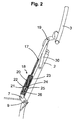
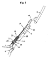
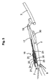
- Fig. 2-5 depicts different positions of the head rest in relation to the back of the chair, in one embodiment of the connecting element according to the present invention, in a length profile.
- Fig. 6 and 7 depicts the connecting element in fig 2-5 in a locked and an uncoupled position, respectively, in larger detail.
- a chair 1 of the type disclosed in WO 92/06621 is mainly shown, which chair 1 comprises an adjustable back of the chair 2 with an adjustable head rest 3.
- the chair specified in fig. 1 has a special adjustment of the head rest 3.
- the head rest is active in that it maintains an upright position when the back of the chair is reclined. In the reclined position of the back of the chair this function of the head rest may be disconnected by pulling the head rest somewhat forward. The head rest may then be reclined.
- a connecting element 18 with a rod 17 is also shown, which is attached at the top to a joint 19 on the head rest, and which in the lower part is attached to a joint 7 on a permanent part of the framework of the chair, in a distance from the axis of rotation 9.
- the connecting element 18 with the rod 17 may take mainly two different length positions and has its shortest length amongst others when the back of the chair 2 is in an upright position, wherein the head rest 3 is almost an extension of the back of the chair 2, and forms its largest angle (almost 180°) with the back of the chair. When the back of the chair 2 is reclined to the position shown in fig.
- the connecting element 18 comprises groove 21, blocking device 22 and coupling organ 24 which cooperate with each other so that the head rest 3 may be affected in the above mentioned ways by changing the length of the connecting element.
- the length of the connecting element 18 is further restricted in this embodiment by the stopping device 25 and track 26.
- the connecting element 18 comprises a guide 20 in the form of a circular cylinder, a blocking device 22 in the form of a sphere, a slider 23 and a stopping device 25.
- the coupling organ 24 is in the form of a first track in slider 23, wherein the coupling organ 24 has a more shallow part A and a deeper part B, which cooperate with the blocking device 22 and a groove 21 in guide 20.
- the connecting element may comprise a track 26 in slider 23 with end restrictions C and D which cooperate with a stopping device 25 placed in a hole in guide 20.
- the stopping device 25 is held in place in guide 20 by a spring ring 27 surrounding the guide 20.
- the main parts of the connecting element such as the guide 20, the slider 23, and the rod 17 may be produced in a mouldable material such as a plastic material.
- the blocking device 22 In an upright position of the back of the chair 2, the blocking device 22 will fall down between the shallow position A in the coupling organ 24 in the slider 23 and the groove 21 in the guide 20, due to gravity as is evident from fig. 2.
- the head rest function is locked.
- a small (manual) pull forwards of the head rest 3 will release the blocking device 22 out of clamp between the shallow position A in the coupling organ 24 and the groove 21, down into the deeper position B of the coupling organ 24 due to gravity, and thereby uncouple the head rest as shown in fig. 5.
- the movement of the head rest 3 is further restricted in this embodiment by the movement of the slider 23 in guide 20 being restricted by the guiders stopping device 25, which run in the gliders track 26 between the end restrictions C and D.
- the movement both forward and backwards is restricted, where the latter is of most current interest in that the slider 23 moves in the direction out of the guide 20 until the stopping device 25 stands against end restriction D in then track 26, see fig. 5 and 7.
- the chair is further equipped with a driver 30 attached to the back of the chair in its one end and to the joint 19 on the head rest in its other end by a track 31, as shown in fig. 4.
- the driver 30 secures the head rest 3 against backward distortion in the reclined position, and brings the head rest 3 with it when the back of the chair 2 is raised up such that the slider 23 moves all the way down into the guide 20 in the upright position, making the blocking device 22 fall down between the groove 21 and position A in the coupling organ 24 again.
- the stopping device with track as described over may be arranged on other places in the connecting element than shown in the figures, or on other movable parts between the back of the chair 2 and the head rest 3, such as for example on the arched guides of the head rest or as separate stopping devices similar to the driver 30, or the function may be attended by the upholstery.
- the driver 30 may likewise be arranged on other places between the back of the chair 2 and the head rest 3, or its function may be attended by the upholstery for example, or devices in the arched guides of the head rest. Further, the driver 30 may be constructed in other ways such as a wire or a similar flexible organ with a certain length.
- the connecting element may in its upper end be formed as a rod 17, which is fastened in the joint 19 on the head rest.
- the rod part may have a shape which gives a suitable elastic flexibility.
- the rod may be somewhat arched or contain at least one slight angle.
- the rod 17 may be attached to the slider 23 in a way that allows rotation and/or variation of the angle between them.
- the guide 20 with slider may have another cross section than circular, such as for example oval or square.
- the blocking device 22 may be a roll or another element influenced by gravity.
- the coupling organ 24 and the groove 21 may have another suitable design adapted to the blocking device 22, such as a simple v-formed track which secures the above mentioned function of the groove 21, blocking device 22 and coupling organ 24.
Landscapes
- Health & Medical Sciences (AREA)
- Dentistry (AREA)
- General Health & Medical Sciences (AREA)
- Chairs For Special Purposes, Such As Reclining Chairs (AREA)
- Mutual Connection Of Rods And Tubes (AREA)
- Semiconductor Lasers (AREA)
- Mechanical Coupling Of Light Guides (AREA)
- Chair Legs, Seat Parts, And Backrests (AREA)
- Coupling Device And Connection With Printed Circuit (AREA)
- Details Of Connecting Devices For Male And Female Coupling (AREA)
- Surface Acoustic Wave Elements And Circuit Networks Thereof (AREA)
- Bipolar Transistors (AREA)
- Braking Arrangements (AREA)
- Electroluminescent Light Sources (AREA)
- Liquid Crystal (AREA)
- Seal Device For Vehicle (AREA)
Claims (10)
- Verbindungselement (18) für einen Sessel (1) mit einem verstellbaren Rückenteil (2) und einer Kopfauflage (3), wobei das Verbindungselement zwischen einem Abschnitt an der Kopfauflage (3) und einem Anbringungsabschnitt am Sessel angeordnet ist, und durch eine Bewegung des verstellbaren Rückenteils des Sessels (2) so angeordnet wird, dass der Winkel der Kopfauflage (3) in Bezug auf das Rückenteil des Sessels (2) beeinflusst wird, wobei der Winkel der Kopfauflage in der nach hinten umgelegten Position des Rückenteils des Sessels (2) verändert werden kann, indem die effektive Länge des Verbindungselements geändert wird, wobei das Verbindungselement (18) eine Führung (20) umfasst, die ein Gleitstück (23) aufnimmt, welche miteinander verrastet werden können,
dadurch gekennzeichnet, dass die Führung (20) und das Gleitstück (23) mit einer durch die Schwerkraft beeinflussten Blockiervorrichtung (22) zusammenwirken, um eine verrastete Verbindungsposition für das Verbindungselement (18) in einem verkürzten Zustand desselben hervorzurufen. - Verbindungselement nach Anspruch 1,
dadurch gekennzeichnet, dass das Verbindungselement (18) mit einer Anschlagvorrichtung (25) ausgeführt ist, die die nach außen gerichtete Bewegung des Gleitstücks (23) in der Führung (20) begrenzt. - Verbindungselement nach Anspruch 2,
dadurch gekennzeichnet, dass die Anschlagvorrichtung (25) aus einem an der Führung (20) angebrachten Anschlag besteht, der in einer Laufbahn (26) im Gleitstück (23) läuft, welche Laufbahn die Bewegung des Gleitstücks (23) in der Führung (20) auf eine erste Endbegrenzung (C) begrenzt und durch eine zweite Endbegrenzung (D) ebenfalls verhindert, dass das Gleitstück (23) aus der Führung (20) herausgezogen wird. - Verbindungselement nach den Ansprüchen 1 bis 3,
dadurch gekennzeichnet, dass die Führung (20) des Verbindungselements (18) und/oder das Gleitstück (23) und/oder ein Stab (17) aus formbarem Material wie Kunststoff besteht/bestehen. - Verbindungselement nach den Ansprüchen 1 bis 4,
dadurch gekennzeichnet, dass das Verbindungselement (18) mit einem Stab (17) ausgestattet ist, der teilweise aus einem flexiblen Material bestehen kann und/oder leicht gekrümmt ist oder zumindest einen leichten Knick enthält. - Verbindungselement nach den Ansprüchen 1 bis 5,
dadurch gekennzeichnet, dass der Stab (17) darüber hinaus am Gleitstück (23) derart angebracht ist, dass eine Drehung und/oder Veränderung des Winkels zwischen ihnen ermöglicht ist. - Verbindungselement nach den Ansprüchen 1 bis 6,
dadurch gekennzeichnet, dass das Verbindungselement einen Querschnitt hat, der hauptsächlich kreisförmig, oval, rechteckig oder mehrkantig, vorzugsweise kreisförmig ist. - Verbindungselement nach den Ansprüchen 1 bis 7,
dadurch gekennzeichnet, dass die Blockiervorrichtung (22) in Form einer Kugel oder eines Zylinders oder einer anderen bewegbaren Blockiervorrichtung vorliegt, vorzugsweise in Form einer Kugel. - Sessel (1) mit einem verstellbaren Rückenteil (2) und einer Kopfauflage (3), mit einem Verbindungselement nach einem der vorhergehenden Ansprüche, das zwischen einem Abschnitt an der Kopfauflage (3) und einem Anbringungsabschnitt am Sessel angeordnet ist, und durch eine Bewegung des verstellbaren Rückenteils des Sessels (2) so angeordnet wird, dass der Winkel der Kopfauflage (3) in Bezug auf das Rückenteil des Sessels (2) beeinflusst wird, wobei der Winkel der Kopfauflage in der nach hinten umgelegten Position des Rückenteils des Sessels (2) verändert werden kann, indem die effektive Länge des Verbindungselements geändert wird,
dadurch gekennzeichnet, dass die Blockiervorrichtung (22) in einer aufrechten Position des Rückenteils des Sessels (2) zwischen einem weniger tiefen Teilbereich (A) eines Kopplungsorgans (24) im Gleitstück (23) und einer Nut (21) in der Führung (20) verrastet ist, um die Kopfauflagenfunktion auszuführen, bis das Rückenteil des Sessels vollständig nach hinten umgelegt ist,- und dass durch einen schwachen (manuellen) nach vorne gerichteten Zug an der Kopfauflage in der nach hinten umgelegten Position des Rückenteils des Sessels die Blockiervorrichtung (22) aus der verriegelten Position gelöst wird und aufgrund der Schwerkraft in die tiefer gelegene Position (B) des Kopplungsorgans (24) fällt, um die Kopfauflage (3) zu entkoppeln,- und dass die Blockiervorrichtung (22) erst in einer erneuten aufrechten Position des Rückenteils des Sessels (2) zwischen dem weniger tiefen Teilbereich (A) im Kopplungsorgan (24) im Gleitstück (23) und der Nut (21) in der Führung (20) wieder nach unten fällt, um die Funktion der Kopfauflage in Zusammenwirken mit dem Verbindungselement (18) wieder herzustellen. - Sessel nach Anspruch 9,
dadurch gekennzeichnet, dass er zusätzlich zu dem Verbindungselement nach einem der Ansprüche 1 bis 9 ein zwischen der Kopfauflage (3) und dem Rückenteil des Sessels (2) angebrachtes Antriebsteil (30) umfasst, das die Drehbewegung der Kopfauflage begrenzt.
Priority Applications (1)
| Application Number | Priority Date | Filing Date | Title |
|---|---|---|---|
| CY20061101549T CY1107655T1 (el) | 2001-07-05 | 2006-10-26 | Συνδετικο στοιχειο δυο σταδιων |
Applications Claiming Priority (3)
| Application Number | Priority Date | Filing Date | Title |
|---|---|---|---|
| NO20013342A NO313783B1 (no) | 2001-07-05 | 2001-07-05 | To-trinns trekkelement |
| NO20013342 | 2001-07-05 | ||
| PCT/NO2002/000248 WO2003003879A1 (en) | 2001-07-05 | 2002-07-05 | Two-step connecting element |
Publications (2)
| Publication Number | Publication Date |
|---|---|
| EP1408794A1 EP1408794A1 (de) | 2004-04-21 |
| EP1408794B1 true EP1408794B1 (de) | 2006-09-13 |
Family
ID=19912641
Family Applications (1)
| Application Number | Title | Priority Date | Filing Date |
|---|---|---|---|
| EP02741546A Expired - Lifetime EP1408794B1 (de) | 2001-07-05 | 2002-07-05 | Zweistufen-verbindungselement |
Country Status (13)
| Country | Link |
|---|---|
| US (2) | US7322641B2 (de) |
| EP (1) | EP1408794B1 (de) |
| JP (1) | JP4276938B2 (de) |
| AT (1) | ATE339132T1 (de) |
| AU (1) | AU2002314645B2 (de) |
| CA (1) | CA2450817C (de) |
| CY (1) | CY1107655T1 (de) |
| DE (1) | DE60214722T2 (de) |
| DK (1) | DK1408794T3 (de) |
| ES (1) | ES2272731T3 (de) |
| NO (1) | NO313783B1 (de) |
| PT (1) | PT1408794E (de) |
| WO (1) | WO2003003879A1 (de) |
Cited By (5)
| Publication number | Priority date | Publication date | Assignee | Title |
|---|---|---|---|---|
| WO2008041868A3 (en) * | 2006-10-04 | 2008-07-31 | Formway Furniture Ltd | A chair |
| USD600051S1 (en) | 2008-04-09 | 2009-09-15 | Formway Furniture Limited | Chair back |
| USD601827S1 (en) | 2008-12-18 | 2009-10-13 | Formway Furniture Limited | Furniture base |
| USD604535S1 (en) | 2008-04-09 | 2009-11-24 | Formway Furniture Limited | Chair |
| USD613084S1 (en) | 2008-12-12 | 2010-04-06 | Formway Furniture Limited | Chair |
Families Citing this family (13)
| Publication number | Priority date | Publication date | Assignee | Title |
|---|---|---|---|---|
| NO326574B1 (no) * | 2007-03-13 | 2009-01-12 | Sapdesign As | Anordning ved stol med justerbar vinkel mellom stolens sete og rygg |
| WO2008129567A1 (en) * | 2007-04-18 | 2008-10-30 | Stema S.R.L. | Mechanism for reclining armchairs or sofas |
| DE202007009877U1 (de) * | 2007-07-14 | 2007-09-20 | Stanzwerk Wetter Sichelschmidt Gmbh & Co. Kg | Sitzmöbel |
| NO328012B1 (no) | 2007-10-10 | 2009-11-09 | Mobeldesign As | Anordning til sittemobel |
| JP5442239B2 (ja) * | 2008-11-19 | 2014-03-12 | 朝日木材加工株式会社 | リクライニングシート |
| DE102010049040A1 (de) * | 2010-10-21 | 2012-04-26 | Carsten Seichter | Sitzmöbel |
| CN102228345B (zh) * | 2011-03-25 | 2013-06-19 | 谢光 | 一种便于健颈的多功能健身椅 |
| DE102014118163A1 (de) * | 2014-12-08 | 2016-06-09 | Ferdinand Lusch Gmbh & Co. Kg | Sitzmöbel mit verschwenkbarem Funktionsteil |
| US9900481B2 (en) * | 2015-11-25 | 2018-02-20 | Semiconductor Components Industries, Llc | Imaging pixels having coupled gate structure |
| FR3052348A1 (fr) * | 2016-06-10 | 2017-12-15 | Didier Monard | Fauteuil inclinable |
| US10450072B2 (en) * | 2017-11-28 | 2019-10-22 | B/E Aerospace, Inc. | Seatback articulation assembly and method |
| NO346789B1 (no) * | 2021-01-11 | 2023-01-09 | H2 Norway As | Sitteanordning |
| NO349580B1 (en) * | 2023-09-21 | 2026-03-02 | Ekornes AS | A recliner |
Family Cites Families (18)
| Publication number | Priority date | Publication date | Assignee | Title |
|---|---|---|---|---|
| US2952303A (en) * | 1958-04-15 | 1960-09-13 | Albert M Spound | Manual and automatically projectible headrest |
| US2989341A (en) * | 1958-12-08 | 1961-06-20 | Anton Lorenz | Head-rest and control |
| US3027194A (en) * | 1959-08-03 | 1962-03-27 | Young Spring & Wire Corp | Headrest assembly for vehicle seats |
| US3191990A (en) * | 1962-05-31 | 1965-06-29 | Rugg Donald Edwin | Reclining mechanism for wheelchairs and the like |
| US3572831A (en) * | 1969-04-21 | 1971-03-30 | American Seating Co | Study unit |
| BE760088A (fr) * | 1969-12-17 | 1971-05-17 | Giroflex Entwicklungs Ag | Chaise basculante |
| US3642088A (en) * | 1970-02-02 | 1972-02-15 | Case Co J I | Self-locating vertically and facingly adjustable seat |
| US4643472A (en) * | 1984-12-24 | 1987-02-17 | Combustion Engineering, Inc. | Rapid installation tube gripper |
| US4693516A (en) * | 1986-08-14 | 1987-09-15 | Knecht Hillery G | Headrest assembly and method for making same |
| DE3636026A1 (de) * | 1986-10-23 | 1988-04-28 | Hilti Ag | Handgeraet mit werkzeughalter |
| NO176384C (no) | 1990-10-12 | 1995-03-29 | Ekornes Fabrikker As J E | Anordning ved en stol, spesielt en stol med regulerbar rygg og nakkestötte |
| US5366313A (en) * | 1992-11-02 | 1994-11-22 | Norco, Inc. | Strut construction |
| IT1291007B1 (it) * | 1997-01-14 | 1998-12-14 | Bruzolo Manifatt Gestind Mb | Appoggiatesta per sedili di autoveicoli |
| US5816658A (en) * | 1997-05-23 | 1998-10-06 | Flexsteel Industries, Inc. | Head rest lock |
| DE19727168C2 (de) * | 1997-06-26 | 2000-08-24 | Grammer Ag | Teleskopartig verstellbare Kopfstütze |
| US5927804A (en) * | 1998-02-11 | 1999-07-27 | Trw Inc. | Vehicle occupant protection apparatus |
| NO991126D0 (no) | 1999-03-08 | 1999-03-08 | Ekornes Asa | Anordning ved en stol, spesielt en stol med regulerbar rygg og nakkest°tte |
| DE10209189A1 (de) * | 2002-03-04 | 2003-09-25 | Daimler Chrysler Ag | Fahrzeugsitz mit neigungsverstellbarer Kopfstütze |
-
2001
- 2001-07-05 NO NO20013342A patent/NO313783B1/no not_active IP Right Cessation
-
2002
- 2002-07-05 JP JP2003509898A patent/JP4276938B2/ja not_active Expired - Lifetime
- 2002-07-05 DK DK02741546T patent/DK1408794T3/da active
- 2002-07-05 DE DE60214722T patent/DE60214722T2/de not_active Expired - Lifetime
- 2002-07-05 US US10/482,932 patent/US7322641B2/en not_active Expired - Lifetime
- 2002-07-05 ES ES02741546T patent/ES2272731T3/es not_active Expired - Lifetime
- 2002-07-05 CA CA2450817A patent/CA2450817C/en not_active Expired - Lifetime
- 2002-07-05 PT PT02741546T patent/PT1408794E/pt unknown
- 2002-07-05 EP EP02741546A patent/EP1408794B1/de not_active Expired - Lifetime
- 2002-07-05 AU AU2002314645A patent/AU2002314645B2/en not_active Expired
- 2002-07-05 AT AT02741546T patent/ATE339132T1/de active
- 2002-07-05 WO PCT/NO2002/000248 patent/WO2003003879A1/en not_active Ceased
-
2006
- 2006-10-26 CY CY20061101549T patent/CY1107655T1/el unknown
-
2007
- 2007-08-22 US US11/894,965 patent/US7594693B2/en not_active Expired - Lifetime
Cited By (14)
| Publication number | Priority date | Publication date | Assignee | Title |
|---|---|---|---|---|
| US8029060B2 (en) | 2006-10-04 | 2011-10-04 | Formway Furniture Limited | Chair |
| US8888183B2 (en) | 2006-10-04 | 2014-11-18 | Formway Furniture Limited | Chair |
| US8668265B2 (en) | 2006-10-04 | 2014-03-11 | Formway Furniture Limited | Chair |
| WO2008041868A3 (en) * | 2006-10-04 | 2008-07-31 | Formway Furniture Ltd | A chair |
| US8613481B2 (en) | 2006-10-04 | 2013-12-24 | Formway Furniture Limited | Chair |
| US8096615B2 (en) | 2006-10-04 | 2012-01-17 | Formay Furniture Limited | Chair |
| US8087727B2 (en) | 2006-10-04 | 2012-01-03 | Formway Furniture Limited | Chair |
| USD604535S1 (en) | 2008-04-09 | 2009-11-24 | Formway Furniture Limited | Chair |
| USD616213S1 (en) | 2008-04-09 | 2010-05-25 | Formway Furniture Limited | Chair |
| USD615784S1 (en) | 2008-04-09 | 2010-05-18 | Formway Furniture Limited | Chair back |
| USD604969S1 (en) | 2008-04-09 | 2009-12-01 | Formway Furniture Limited | Chair back component |
| USD600051S1 (en) | 2008-04-09 | 2009-09-15 | Formway Furniture Limited | Chair back |
| USD613084S1 (en) | 2008-12-12 | 2010-04-06 | Formway Furniture Limited | Chair |
| USD601827S1 (en) | 2008-12-18 | 2009-10-13 | Formway Furniture Limited | Furniture base |
Also Published As
| Publication number | Publication date |
|---|---|
| ES2272731T3 (es) | 2007-05-01 |
| US7322641B2 (en) | 2008-01-29 |
| US20040239154A1 (en) | 2004-12-02 |
| HK1060265A1 (en) | 2004-08-06 |
| WO2003003879A1 (en) | 2003-01-16 |
| DE60214722T2 (de) | 2007-09-13 |
| EP1408794A1 (de) | 2004-04-21 |
| NO20013342A (no) | 2002-12-02 |
| CY1107655T1 (el) | 2013-04-18 |
| DK1408794T3 (da) | 2007-01-29 |
| DE60214722D1 (de) | 2006-10-26 |
| ATE339132T1 (de) | 2006-10-15 |
| JP4276938B2 (ja) | 2009-06-10 |
| US20070290529A1 (en) | 2007-12-20 |
| US7594693B2 (en) | 2009-09-29 |
| NO313783B1 (no) | 2002-12-02 |
| JP2004530522A (ja) | 2004-10-07 |
| NO20013342D0 (no) | 2001-07-05 |
| PT1408794E (pt) | 2007-01-31 |
| CA2450817A1 (en) | 2003-01-16 |
| AU2002314645B2 (en) | 2007-07-19 |
| CA2450817C (en) | 2011-02-01 |
Similar Documents
| Publication | Publication Date | Title |
|---|---|---|
| US7594693B2 (en) | Two-step connecting element | |
| AU2002314645A1 (en) | Two-step connecting element | |
| US5472261A (en) | Arrangement in a recline chair | |
| US6132001A (en) | Adjustment device for an arm of a chair | |
| CA2428935C (en) | Height adjustable arm assembly | |
| DE10030022C2 (de) | Ergonomischer Büro-Stuhl mit Auslegerfuß | |
| WO2005122833A3 (en) | Backrest and adjustable arm for a chair | |
| US6375261B1 (en) | Chair | |
| US6139106A (en) | Headrest for dental use | |
| CN107536317B (zh) | 具有两个弹簧的座椅倾斜机构 | |
| WO2006138523A3 (en) | Reversible lounge chair | |
| HK1060265B (en) | Two-step connecting element | |
| CN107161201A (zh) | 一种童车座椅靠背调节装置 | |
| CN216059890U (zh) | 一种座椅的运动调节结构及运动座椅 | |
| WO1984002074A1 (en) | An arrangement for supporting a person | |
| EP1616504A2 (de) | Teleskopische Armlehne | |
| CN206615269U (zh) | 一种童车座椅靠背调节装置 | |
| CN210810085U (zh) | 座椅椅背角度调整定位机构 | |
| CN218390382U (zh) | 一种座框靠背阻尼联动机构 | |
| CN220800554U (zh) | 一种多部位可调节的座椅 | |
| CN222676567U (zh) | 一种医用手部牵引装置 | |
| CN219782042U (zh) | 一种靠背角度可调节的看台椅 | |
| CN2618499Y (zh) | 活动靠背椅 | |
| KR20230068846A (ko) | 자세 교정용 의자 탈착형 어깨 걸이구 | |
| EP0901762A1 (de) | Verstellvorrichtung für Stühle |
Legal Events
| Date | Code | Title | Description |
|---|---|---|---|
| PUAI | Public reference made under article 153(3) epc to a published international application that has entered the european phase |
Free format text: ORIGINAL CODE: 0009012 |
|
| 17P | Request for examination filed |
Effective date: 20040115 |
|
| AK | Designated contracting states |
Kind code of ref document: A1 Designated state(s): AT BE BG CH CY CZ DE DK EE ES FI FR GB GR IE IT LI LU MC NL PT SE SK TR |
|
| AX | Request for extension of the european patent |
Extension state: AL LT LV MK RO SI |
|
| REG | Reference to a national code |
Ref country code: HK Ref legal event code: DE Ref document number: 1060265 Country of ref document: HK |
|
| GRAP | Despatch of communication of intention to grant a patent |
Free format text: ORIGINAL CODE: EPIDOSNIGR1 |
|
| GRAS | Grant fee paid |
Free format text: ORIGINAL CODE: EPIDOSNIGR3 |
|
| GRAA | (expected) grant |
Free format text: ORIGINAL CODE: 0009210 |
|
| AK | Designated contracting states |
Kind code of ref document: B1 Designated state(s): AT BE BG CH CY CZ DE DK EE ES FI FR GB GR IE IT LI LU MC NL PT SE SK TR |
|
| PG25 | Lapsed in a contracting state [announced via postgrant information from national office to epo] |
Ref country code: IT Free format text: LAPSE BECAUSE OF FAILURE TO SUBMIT A TRANSLATION OF THE DESCRIPTION OR TO PAY THE FEE WITHIN THE PRESCRIBED TIME-LIMIT;WARNING: LAPSES OF ITALIAN PATENTS WITH EFFECTIVE DATE BEFORE 2007 MAY HAVE OCCURRED AT ANY TIME BEFORE 2007. THE CORRECT EFFECTIVE DATE MAY BE DIFFERENT FROM THE ONE RECORDED. Effective date: 20060913 |
|
| REG | Reference to a national code |
Ref country code: GB Ref legal event code: FG4D |
|
| REG | Reference to a national code |
Ref country code: CH Ref legal event code: EP |
|
| REG | Reference to a national code |
Ref country code: IE Ref legal event code: FG4D |
|
| REF | Corresponds to: |
Ref document number: 60214722 Country of ref document: DE Date of ref document: 20061026 Kind code of ref document: P |
|
| REG | Reference to a national code |
Ref country code: HK Ref legal event code: GR Ref document number: 1060265 Country of ref document: HK |
|
| REG | Reference to a national code |
Ref country code: CH Ref legal event code: NV Representative=s name: PATENTANWAELTE SCHAAD, BALASS, MENZL & PARTNER AG |
|
| REG | Reference to a national code |
Ref country code: SE Ref legal event code: TRGR |
|
| REG | Reference to a national code |
Ref country code: GR Ref legal event code: EP Ref document number: 20060404255 Country of ref document: GR |
|
| REG | Reference to a national code |
Ref country code: DK Ref legal event code: T3 |
|
| REG | Reference to a national code |
Ref country code: PT Ref legal event code: SC4A Free format text: AVAILABILITY OF NATIONAL TRANSLATION Effective date: 20061213 |
|
| REG | Reference to a national code |
Ref country code: EE Ref legal event code: FG4A Ref document number: E000722 Country of ref document: EE Effective date: 20061212 |
|
| ET | Fr: translation filed | ||
| REG | Reference to a national code |
Ref country code: ES Ref legal event code: FG2A Ref document number: 2272731 Country of ref document: ES Kind code of ref document: T3 |
|
| PLBE | No opposition filed within time limit |
Free format text: ORIGINAL CODE: 0009261 |
|
| STAA | Information on the status of an ep patent application or granted ep patent |
Free format text: STATUS: NO OPPOSITION FILED WITHIN TIME LIMIT |
|
| 26N | No opposition filed |
Effective date: 20070614 |
|
| REG | Reference to a national code |
Ref country code: EE Ref legal event code: HC1A Ref document number: E000722 Country of ref document: EE |
|
| REG | Reference to a national code |
Ref country code: FR Ref legal event code: PLFP Year of fee payment: 15 |
|
| REG | Reference to a national code |
Ref country code: FR Ref legal event code: PLFP Year of fee payment: 16 |
|
| REG | Reference to a national code |
Ref country code: FR Ref legal event code: PLFP Year of fee payment: 17 |
|
| PGFP | Annual fee paid to national office [announced via postgrant information from national office to epo] |
Ref country code: NL Payment date: 20210630 Year of fee payment: 20 Ref country code: SK Payment date: 20210630 Year of fee payment: 20 Ref country code: PT Payment date: 20210624 Year of fee payment: 20 |
|
| PGFP | Annual fee paid to national office [announced via postgrant information from national office to epo] |
Ref country code: BE Payment date: 20210629 Year of fee payment: 20 Ref country code: SE Payment date: 20210630 Year of fee payment: 20 Ref country code: DK Payment date: 20210630 Year of fee payment: 20 |
|
| PGFP | Annual fee paid to national office [announced via postgrant information from national office to epo] |
Ref country code: AT Payment date: 20210629 Year of fee payment: 20 Ref country code: CZ Payment date: 20210630 Year of fee payment: 20 Ref country code: EE Payment date: 20210712 Year of fee payment: 20 Ref country code: FI Payment date: 20210707 Year of fee payment: 20 Ref country code: CY Payment date: 20210625 Year of fee payment: 20 Ref country code: BG Payment date: 20210630 Year of fee payment: 20 Ref country code: FR Payment date: 20210708 Year of fee payment: 20 Ref country code: MC Payment date: 20210709 Year of fee payment: 20 Ref country code: LU Payment date: 20210726 Year of fee payment: 20 Ref country code: IT Payment date: 20210716 Year of fee payment: 20 Ref country code: IE Payment date: 20210723 Year of fee payment: 20 |
|
| PGFP | Annual fee paid to national office [announced via postgrant information from national office to epo] |
Ref country code: GR Payment date: 20210726 Year of fee payment: 20 Ref country code: TR Payment date: 20210702 Year of fee payment: 20 Ref country code: DE Payment date: 20210727 Year of fee payment: 20 Ref country code: CH Payment date: 20210714 Year of fee payment: 20 Ref country code: GB Payment date: 20210712 Year of fee payment: 20 Ref country code: ES Payment date: 20210802 Year of fee payment: 20 |
|
| REG | Reference to a national code |
Ref country code: DE Ref legal event code: R071 Ref document number: 60214722 Country of ref document: DE |
|
| REG | Reference to a national code |
Ref country code: NL Ref legal event code: MK Effective date: 20220704 |
|
| REG | Reference to a national code |
Ref country code: DK Ref legal event code: EUP Expiry date: 20220705 |
|
| REG | Reference to a national code |
Ref country code: CH Ref legal event code: PL |
|
| REG | Reference to a national code |
Ref country code: SK Ref legal event code: MK4A Ref document number: E 1274 Country of ref document: SK Expiry date: 20220705 Ref country code: GB Ref legal event code: PE20 Expiry date: 20220704 Ref country code: ES Ref legal event code: FD2A Effective date: 20220727 |
|
| PG25 | Lapsed in a contracting state [announced via postgrant information from national office to epo] |
Ref country code: CZ Free format text: LAPSE BECAUSE OF EXPIRATION OF PROTECTION Effective date: 20220705 |
|
| REG | Reference to a national code |
Ref country code: BE Ref legal event code: MK Effective date: 20220705 |
|
| REG | Reference to a national code |
Ref country code: FI Ref legal event code: MAE |
|
| REG | Reference to a national code |
Ref country code: AT Ref legal event code: MK07 Ref document number: 339132 Country of ref document: AT Kind code of ref document: T Effective date: 20220705 |
|
| REG | Reference to a national code |
Ref country code: SE Ref legal event code: EUG |
|
| REG | Reference to a national code |
Ref country code: IE Ref legal event code: MK9A |
|
| PG25 | Lapsed in a contracting state [announced via postgrant information from national office to epo] |
Ref country code: SK Free format text: LAPSE BECAUSE OF EXPIRATION OF PROTECTION Effective date: 20220705 Ref country code: PT Free format text: LAPSE BECAUSE OF EXPIRATION OF PROTECTION Effective date: 20220713 Ref country code: IE Free format text: LAPSE BECAUSE OF EXPIRATION OF PROTECTION Effective date: 20220705 Ref country code: GB Free format text: LAPSE BECAUSE OF EXPIRATION OF PROTECTION Effective date: 20220704 Ref country code: ES Free format text: LAPSE BECAUSE OF EXPIRATION OF PROTECTION Effective date: 20220706 |