EP1409186B1 - Dispositif d'erosion comprenant une tete d'erosion concue pour eliminer des elements de connexion metalliques - Google Patents
Dispositif d'erosion comprenant une tete d'erosion concue pour eliminer des elements de connexion metalliques Download PDFInfo
- Publication number
- EP1409186B1 EP1409186B1 EP02764526A EP02764526A EP1409186B1 EP 1409186 B1 EP1409186 B1 EP 1409186B1 EP 02764526 A EP02764526 A EP 02764526A EP 02764526 A EP02764526 A EP 02764526A EP 1409186 B1 EP1409186 B1 EP 1409186B1
- Authority
- EP
- European Patent Office
- Prior art keywords
- erosion
- drill head
- connecting element
- positioning
- dielectric
- Prior art date
- Legal status (The legal status is an assumption and is not a legal conclusion. Google has not performed a legal analysis and makes no representation as to the accuracy of the status listed.)
- Expired - Lifetime
Links
- 230000003628 erosive effect Effects 0.000 title claims description 65
- 239000002184 metal Substances 0.000 title 1
- 238000000034 method Methods 0.000 claims description 36
- 230000008569 process Effects 0.000 claims description 27
- 238000011010 flushing procedure Methods 0.000 claims description 14
- 238000012545 processing Methods 0.000 claims description 13
- 238000009760 electrical discharge machining Methods 0.000 claims description 12
- 230000009471 action Effects 0.000 claims description 2
- 238000012544 monitoring process Methods 0.000 claims 2
- 238000004886 process control Methods 0.000 claims 2
- 230000000694 effects Effects 0.000 claims 1
- 238000012937 correction Methods 0.000 description 4
- 238000005553 drilling Methods 0.000 description 4
- 239000000463 material Substances 0.000 description 4
- 230000008901 benefit Effects 0.000 description 3
- 239000002826 coolant Substances 0.000 description 3
- 239000002131 composite material Substances 0.000 description 2
- 230000001276 controlling effect Effects 0.000 description 2
- 230000001419 dependent effect Effects 0.000 description 2
- 238000013461 design Methods 0.000 description 2
- 230000035515 penetration Effects 0.000 description 2
- 230000009467 reduction Effects 0.000 description 2
- 238000013459 approach Methods 0.000 description 1
- 239000004918 carbon fiber reinforced polymer Substances 0.000 description 1
- 230000008859 change Effects 0.000 description 1
- 238000010276 construction Methods 0.000 description 1
- 239000008367 deionised water Substances 0.000 description 1
- 229910021641 deionized water Inorganic materials 0.000 description 1
- 238000001514 detection method Methods 0.000 description 1
- 238000011161 development Methods 0.000 description 1
- 238000010586 diagram Methods 0.000 description 1
- 239000007772 electrode material Substances 0.000 description 1
- 239000002245 particle Substances 0.000 description 1
- 210000004258 portal system Anatomy 0.000 description 1
- 230000001105 regulatory effect Effects 0.000 description 1
- 238000007789 sealing Methods 0.000 description 1
- 230000007704 transition Effects 0.000 description 1
- XLYOFNOQVPJJNP-UHFFFAOYSA-N water Chemical compound O XLYOFNOQVPJJNP-UHFFFAOYSA-N 0.000 description 1
- 230000003313 weakening effect Effects 0.000 description 1
Images


Classifications
-
- B—PERFORMING OPERATIONS; TRANSPORTING
- B23—MACHINE TOOLS; METAL-WORKING NOT OTHERWISE PROVIDED FOR
- B23H—WORKING OF METAL BY THE ACTION OF A HIGH CONCENTRATION OF ELECTRIC CURRENT ON A WORKPIECE USING AN ELECTRODE WHICH TAKES THE PLACE OF A TOOL; SUCH WORKING COMBINED WITH OTHER FORMS OF WORKING OF METAL
- B23H9/00—Machining specially adapted for treating particular metal objects or for obtaining special effects or results on metal objects
- B23H9/14—Making holes
-
- B—PERFORMING OPERATIONS; TRANSPORTING
- B21—MECHANICAL METAL-WORKING WITHOUT ESSENTIALLY REMOVING MATERIAL; PUNCHING METAL
- B21J—FORGING; HAMMERING; PRESSING METAL; RIVETING; FORGE FURNACES
- B21J15/00—Riveting
- B21J15/38—Accessories for use in connection with riveting, e.g. pliers for upsetting; Hand tools for riveting
- B21J15/50—Removing or cutting devices for rivets
-
- B—PERFORMING OPERATIONS; TRANSPORTING
- B23—MACHINE TOOLS; METAL-WORKING NOT OTHERWISE PROVIDED FOR
- B23H—WORKING OF METAL BY THE ACTION OF A HIGH CONCENTRATION OF ELECTRIC CURRENT ON A WORKPIECE USING AN ELECTRODE WHICH TAKES THE PLACE OF A TOOL; SUCH WORKING COMBINED WITH OTHER FORMS OF WORKING OF METAL
- B23H9/00—Machining specially adapted for treating particular metal objects or for obtaining special effects or results on metal objects
-
- B—PERFORMING OPERATIONS; TRANSPORTING
- B23—MACHINE TOOLS; METAL-WORKING NOT OTHERWISE PROVIDED FOR
- B23H—WORKING OF METAL BY THE ACTION OF A HIGH CONCENTRATION OF ELECTRIC CURRENT ON A WORKPIECE USING AN ELECTRODE WHICH TAKES THE PLACE OF A TOOL; SUCH WORKING COMBINED WITH OTHER FORMS OF WORKING OF METAL
- B23H9/00—Machining specially adapted for treating particular metal objects or for obtaining special effects or results on metal objects
- B23H9/001—Disintegrating
Definitions
- the invention relates to an erosion device with an erosion head for removing metallic fasteners.
- core hole drills have heretofore been used to secure the fastener to be removed, e.g. to cut the rivet, centric.
- a disadvantage of this drilling method is that structural parts held together by the fasteners may be damaged. This is particularly the case when rivets are to be removed, since they must be drilled to the transition point lying between the rivet head and the neck neck and abut at this point the structural parts connected to the rivet.
- this drilling method requires a very heavy physical load of the executing craftsman, which additionally affects the quality of this process.
- the US 3620635 discloses a device for Nietaufentfernung according to the principle of Nietaufbohrung.
- a method and a device for removing fasteners is known in which Niet: YAG laser beam Nietkopffflanken be separated, said laser beam is guided circularly through an optic and the corresponding radius of the circle and the penetration depth are controlled.
- a program control device controlled the rotational speed of the motor and the switch-on of the laser to achieve certain penetration depths.
- the US 4 259 562 A and the US Pat. No. 5,618,449 disclose rivet-removal devices having an axially movable hollow electrode through which the coolant removes the particles produced by the erosion process. After US Pat. No. 5,618,449 the feed rate of the electrode is controlled. In the US Pat. No. 5,618,449 discloses a coolant system with which a constant flow of coolant is effected.
- the object of the invention is to provide a drilling method and a device for carrying out the method, with the most economical removal of fasteners from structural parts is possible, and the structural parts remain as reliable as possible undamaged.
- An advantage of the device according to the invention is that with this or with this a reduction of process times and a reduction of tool wear can be achieved.
- the device according to the invention further enables an ergonomically advantageous sequence without extraordinary physical stress for the executing craftsman.
- the the drill head 4 facing structure surface is in the Fig. 2 with the reference F and the drill head 4 facing surface of the connecting element is denoted by the reference S.
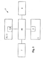
- a positioning sensor 7 is arranged, by means of which a determination of the position of the drill head 4 relative to the respectively to be removed Veitatiselement V is vorrisebar.
- the positioning sensor 7 is preferably realized as a surface sensor and in particular as a laser sensor and may additionally comprise a video camera.
- the positioning sensor system 7 is preferably associated with an image processing unit 9, with which the Detecting the position of the connector V can be improved by improved recognition of the connector geometry.
- the video camera can optionally also be provided for controlling the chemical-mechanical erosion process.
- the control of the positioning system 1 on the basis of the data from the positioning sensor and possibly the image processing unit 9 is performed by the positioning controller 2.
- the required parameters for the relative alignment of the drill head carrier 4a to the workpiece W or to the connecting element V are detected by the positioning sensor 7.
- the image processing unit 9 the exact positioning by an image recognition sensor in the form of, for example, at least one camera module, and a suitable image processing system, wherein the image recognition sensor is preferably attached to the drill head carrier 4a.
- the video camera if provided, is connected to a control monitor 9a via a video signal cable 9b.
- any other type of suitable control device may be provided for controlling the rough positioning.
- the advantage of using a video camera is that it can also be used to control the erosion process.
- the first camera module allows the detection of a larger number of fasteners or connectors V, which can be used on a separate monitor for Groborienttechnik and positioning of the drill head 4 with respect to the workpiece W.
- the individual connecting elements V for the image processing system are optically detected.
- the image processing system determines the connector center and determines the coordinates that are stored and over which the drill head can be placed again at any time exactly above the connector once detected.
- the described functions can also be fulfilled by this one camera module.
- more than two camera modules can be provided, to which the described functions can be distributed in a suitable manner.
- the actual removal of the connector is carried out by a spark erosion system 10 with the erosion head 3 and a stationary equipment 11.
- the erosion head 3 prepares the connecting element V by weakening or erosion of the shank of the connecting element V so far that this in turn by knocking out or pulling it out can be removed.
- the control of the erosion head 4 takes place by means of an erosion control unit 13.
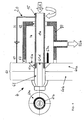
- the spark erosion system ( Fig. 2 and 3 ) comprises for carrying out the actual erosion process, the erosion head 3 with a rotatable tube electrode 15 and a Spülkarfig 17.
- the rotary drive 6 with the drill head 3 is seated on a feed carriage 18 of the linear feed unit 5, which also has a feed drive 19 for its drive.
- the erosion control unit 13 Controlled by the erosion control unit 13, the advancement of the tubular electrode 15 in the z-direction (FIG. Fig. 2 ) accomplished.
- the rotary drive 6 allows rotational movements of the drill head 4 about two perpendicular axes, in the representation of Fig. 2 around the vertical or x-axis and around the horizontal or y-axis.
- the rotation about the x-axis results in an adjustment angle ⁇
- the rotation about the y-axis results in an adjustment angle ⁇ of the erosion head 3.
- the erosion head 3 can be positioned in the y- and x-direction. This is preferably done before the actual erosion process.
- the positioning system 1 can be realized for this purpose by a surface gantry with two linear axes in the x and y directions. However, other positioning devices of the prior art may be used.
- the erosion head 3 is brought to a suitable point on the surface S of the connecting element V to be removed, from which the erosion process can start. If the pre-positioning of the erosion head 3 has taken place, the positioning system is initially locked until, if necessary, corrections are still required during the erosion process.
- this pre-positioning of the erosion head 3 is additionally aligned by means of the rotary drive 6 in order to accomplish a suitable alignment of the erosion head 3 before the start of the erosion process.
- this pre-positioning is carried out automatically by means of the positioning sensor system, optionally by means of the image processing unit 9 and by means of the positioning control 2, but can also be semi-automatic or manual.
- the preferred design of the positioning system 1 is described as a surface portal:
- the surface gantry has an x- and a y-axis axis, whereby the drill head 4 or the erosion head 3 can move parallel to the workpiece surface of the workpiece W and in particular to the head or the surface S of the connecting element V to be removed in the workpiece W.
- the positional orientation of the drill head 4 relative to the workpiece W is determined by three laser distance sensors, which are mounted on the drill head carrier, parallel to the axis of the electrode 15 arranged on the erosion head 3.
- connection element is accessible from the side of the workpiece W opposite the erosion system, so that this only extends as far as the erosion of a groove it must be weakened that it can subsequently be knocked out to the rear. If this accessibility is missing from the perspective of the erosion system to the rear, the entire connector shaft must be eroded so that the connecting element V can be pulled out to the front.
- a further laser distance sensor preferably a point laser, is used, over which the drill head 4 is aligned relative to the connector surface S in order to follow the course of the connector shaft exactly axially during erosion can.
- the technical characteristics of the positioning system can include various combinations of local and global positioning (maximization, miniaturization).
- corrections in the alignment of the eroding head 3 or the electrode by means of the rotary drive 6 or also in the x or y direction may be required during the erosion process. These corrections can also be made during the erosion process, including the positioning sensor 7, optionally the image processing unit 9 and the positioning controller 2 can be used.
- the flushing cage 17 is part of a flushing system 20, which further comprises a filter unit 21 and a pump 22.
- a medium serving as a dielectric is supplied via a feed line 22a to the Spülkalfig 7, which in turn can be supplied from this by means of a suction line 22b of the filter system 21.
- the filter unit 21 serves to clean the dielectric, while the pump 22 serves to supply the dielectric with sufficient pressure to the flushing cage 7.
- An erosion energy device 30 is provided, which sends via a line 31 erosion current to the electrode 15, with which the erosion process is effected on the workpiece.
- An erosion control device 40 controls the erosion process.
- a sensor 43 is provided, which picks up the position. By means of the signal line 44, the actual position of the linear axis or the drill head is supplied to the control unit 40, which emits commands for the feed drive 19 by means of a controller.
- the sensor 43 may for example be designed as a rotary encoder and connected to the feed drive 19.
- the control unit 40 is connected via an input line 45 to an input device of the process controller 47, with which process instructions can be introduced into the controller 40 for designing the erosion method.
- the erosion controller sends control signals to the erosion energy source 30, with which the strength and the course of the erosion or gap current is determined and controlled, e.g. the pulse lengths, the average amplitude heights and amplitude maxima or the pulse pauses of the erosion current.
- Various parameters can be incorporated, such as electrode material, workpiece material and size, or the dielectric used.
- the control specifications determined by the erosion control unit represent an optimum for the current to be delivered by the erosion energy source.
- the flushing cage 17 ( Fig. 3 ) closes an inner space 7 a around the connecting element V seated in the workpiece W in a region of the tubular electrode 15.
- the space 7a is supplied via the feed line 22a, a dielectric.
- Deionized water having a conductivity of preferably 10 to 60 ⁇ S / cm, but depending on the application also beyond this range, is advantageously used as the dielectric.
- the space 7a is almost completely filled with a dielectric.
- a seal 62 is provided between the flushing cage 17 and the tubular electrode 5 and a seal 63 for sealing the flushing cage 17 with respect to the workpiece W or the structure.
- the workpiece W may comprise a plurality of structural parts in the region of the connecting element V.
- the workpiece or the structure is in the FIG. 4 with the reference numeral 60 and the connecting element is in the FIG. 4 designated by the reference numeral 61.
- the structure 60 may typically include a plank 60a and a substructure 60b, such as a bulkhead in an aircraft structure.
- the rinsing cage 17 is arranged so that the location on the structure 60, on which the connecting element 61 is arranged, can be completely immersed in dielectric.
- the flushing cage 17 must therefore enclose the entire connecting element 61 on the side of the tubular electrode 15.
- the erosion process can be carried out in any desired spatial position of the workpiece 61 or also of the drill head 4.
- An advantage of this design of the flushing system 20 is that it enables a sealed, position-independent erosion of the connecting element V by point flushing with ground contact on the connecting element.
- the tubular electrode 15 is rotatably arranged opposite the flushing cage 7 and opposite the connecting element 61 and protrudes through the flushing cage 7.
- the grounding line 67 is connected, which alternatively also has a special contact 67a with the connecting element 61 (FIG. Fig. 4 ) can be connected.
- the latter case is to be provided according to the invention if the structure 60 is only poorly or not electrically conductive, that is to say, for example, is a CFRP structure.
- the interior 15a of the tube electrode 15 is charged via the feed line 22a with dielectric, which up to the tube electrode 5 facing surface 61a and S (FIG. Fig. 2 ) of the connecting element 61 or V is guided.
- the Fig. 4 shows a state in which the tube electrode 15 has already formed ring groove 61 b in the connecting element 61 due to the erosion process. It can be seen that between the annular groove 61 b and the tube electrode 5, a gap 61c is formed.
- the dielectric located in the interior 7a flows through the intermediate space 61c into the space 7a of the flushing cage 7 in order to be able to be guided to the filter system 21 via the suction line 22b.
- the dielectric coming from the intermediate space 61c carries with it removal material that has arisen from the connecting element 61 in the erosion process. In this way, removal material is removed via the line 22b from the processing site.
- the tube electrode 15 is rotated by the rotary drive 6 for the erosion process to prevent uneven wear of the workpiece side surface of the electrode. This is particularly important if the surface 61 a of the connecting element before the erosion process an uneven, e.g. having grooved surface.
- the electrode 15 is initially attached to the axis parallel to the connecting element 61 or surface orthogonal to the structure 60. This is done via the sensor system 7, which is preferably realized as a laser distance sensor.
- the tube electrode 15 is rotated and the pump 22 is turned on to feed the interior 15a of the tube electrode 15 with dielectric. As a result, the dielectric flows from the filter system 21 via the feed line 22a through the interior 5a of the tube electrode and the intermediate space 61c into the interior 7a and then via the suction line 22b back into the filter system 21.
- a ground connection to the workpiece or to the connecting element is to be produced by means of the special contact 67a in the rinsing system 20
- a suitable type of electrode with respect to the type of connector to be removed.
- the drill head 4 is aligned by means of the positioning system 1 with respect to the to be removed connecting element V and 61 and the electrode 15 optionally centered with the aid of the image processing unit 9 on the surface S and 61a of the connecting element V and 61 and required fine corrections performed. Then the actual erosion process is performed.
- eroded connecting elements are removed by means of punch-through.
Landscapes
- Engineering & Computer Science (AREA)
- Mechanical Engineering (AREA)
- Physics & Mathematics (AREA)
- Thermal Sciences (AREA)
- Electrical Discharge Machining, Electrochemical Machining, And Combined Machining (AREA)
Claims (4)
- Équipement d'électroérosion destiné à retirer des éléments de liaison d'une structure (W, 60) comprenant une tête de perçage (3), un mécanisme d'entraînement rotatif (6) avec lequel un outil est mis en rotation, un équipement de positionnement (15) pour déplacer l'outil ainsi qu'une commande de processus (47) pour commander la totalité de l'équipement, l'équipement d'électroérosion comprenant une source d'énergie (30) et un circuit électrique et l'outil étant une électrode tubulaire (15) à travers l'espace intérieur (15a) de laquelle peut être acheminé un diélectrique jusqu'à la surface (61a) de l'élément de liaison (61) à détacher afin de provoquer une tension entre l'électrode tubulaire (15) et l'élément de liaison (61) à détacher en vue de réaliser une électroérosion,
caractérisé en ce
que le mécanisme d'entraînement rotatif (6), pour mettre l'électrode tubulaire en rotation, est disposé sur un chariot d'approche à mobilité linéaire et il est prévu un dispositif de détection de la position sur la tête de perçage pour déterminer la position de la tête de perçage par rapport à l'élément de liaison,
qu'il est prévu au moins une caméra vidéo avec une unité à moniteur associée munie d'une unité de traitement d'image pour le positionnement de la tête de perçage et pour le contrôle du processus d'érosion chimico-mécanique,
que la commande de processus (47) comprend un détecteur d'écart à laser en liaison avec un module de commande d'érosion (40) afin de contrôler la position de la tête de perçage (4) par rapport à la surface du connecteur (S) par le biais de la position du chariot d'approche (18), et envoie des signaux à la source d'énergie (30) pour contrôler la durée des impulsions, les hauteurs d'amplitude moyennes et les maximums d'amplitude ainsi que les pauses d'impulsion du courant d'érosion. - Équipement d'électroérosion destiné à retirer des éléments de liaison selon la revendication 1, caractérisé en ce que l'espace (7a) autour de la surface de l'élément de liaison (V, 61) à usiner est fermé hermétiquement pour empêcher la sortie de diélectrique au moyen d'une cage de rinçage (17) et d'une garniture d'étanchéité (63) et une zone autour de la surface (S) à usiner de l'élément de liaison sur le côté de l'électrode tubulaire (15) et une partie de l'électrode tubulaire (15) peuvent être rincées avec le diélectrique.
- Équipement d'électroérosion destiné à retirer des éléments de liaison selon l'une des revendications précédentes, caractérisé en ce qu'il est prévu un équipement de positionnement (1) ainsi qu'un dispositif de détection (7) sur la tête de perçage (4) pour positionner la tête de perçage (4) par rapport à l'élément de liaison (V, 61).
- Équipement d'électroérosion destiné à retirer des éléments de liaison selon l'une des revendications précédentes, caractérisé en ce qu'il est prévu une unité de commande d'érosion (40) qui, en collaboration avec le dispositif de détection (7), permet de contrôler le processus d'érosion.
Applications Claiming Priority (3)
| Application Number | Priority Date | Filing Date | Title |
|---|---|---|---|
| DE10135587 | 2001-07-20 | ||
| DE10135587A DE10135587C2 (de) | 2001-07-20 | 2001-07-20 | Erodier-Vorrichtung mit einem Erodier-Kopf zum Entfernen von metallischen Verbindungselementen |
| PCT/DE2002/002670 WO2003013775A1 (fr) | 2001-07-20 | 2002-07-22 | Dispositif d'erosion comprenant une tete d'erosion concue pour eliminer des elements de connexion metalliques |
Publications (2)
| Publication Number | Publication Date |
|---|---|
| EP1409186A1 EP1409186A1 (fr) | 2004-04-21 |
| EP1409186B1 true EP1409186B1 (fr) | 2008-10-01 |
Family
ID=7692633
Family Applications (1)
| Application Number | Title | Priority Date | Filing Date |
|---|---|---|---|
| EP02764526A Expired - Lifetime EP1409186B1 (fr) | 2001-07-20 | 2002-07-22 | Dispositif d'erosion comprenant une tete d'erosion concue pour eliminer des elements de connexion metalliques |
Country Status (6)
| Country | Link |
|---|---|
| US (1) | US7015411B2 (fr) |
| EP (1) | EP1409186B1 (fr) |
| CA (1) | CA2453484C (fr) |
| DE (2) | DE10135587C2 (fr) |
| PL (1) | PL208251B1 (fr) |
| WO (1) | WO2003013775A1 (fr) |
Families Citing this family (10)
| Publication number | Priority date | Publication date | Assignee | Title |
|---|---|---|---|---|
| DE10356394B4 (de) * | 2003-12-03 | 2005-11-24 | Eads Deutschland Gmbh | Erosions-Anlage zur formgebenden Bearbeitung eines metallischen Struktur-Bauteils oder eines metallischen Einsatz-Elementes in einem Struktur-Bauteil sowie Erosions-Verfahren |
| US7784163B2 (en) * | 2005-03-22 | 2010-08-31 | The Boeing Company | Riveted fastener extraction apparatuses and method |
| US7214901B1 (en) * | 2006-01-17 | 2007-05-08 | General Electric Company | Duplex electrical discharge machining |
| WO2012102993A2 (fr) * | 2011-01-24 | 2012-08-02 | Perfect Point Edm Corporation | Procédé et dispositif de positionnement pour désagrégation électrique sans action mécanique |
| WO2012103017A2 (fr) * | 2011-01-24 | 2012-08-02 | Perfect Point Edm Corporation | Pièce de centrage adaptable à tête saillante |
| US9878386B2 (en) * | 2013-10-31 | 2018-01-30 | Foundation Of Soongsil University-Industry Cooperation | Eccentric electrode for electric discharge machining, method of manufacturing the same, and micro electric discharge machining apparatus including the same |
| CN104842030A (zh) * | 2015-05-21 | 2015-08-19 | 烟台鲁宝钢管有限责任公司 | 一种带有外部对中夹紧装置的管坯电火花定心机 |
| JP6404875B2 (ja) * | 2016-09-21 | 2018-10-17 | ファナック株式会社 | ワイヤ放電加工機 |
| US10954739B2 (en) | 2018-11-19 | 2021-03-23 | Saudi Arabian Oil Company | Smart rotating control device apparatus and system |
| EP3881950A1 (fr) * | 2020-03-16 | 2021-09-22 | Aerocircular N.V. | Dispositif de retrait de rivets, procédé de retrait de rivets à partir d'un assemblage de composants |
Family Cites Families (12)
| Publication number | Priority date | Publication date | Assignee | Title |
|---|---|---|---|---|
| US3354073A (en) * | 1963-11-22 | 1967-11-21 | Gen Motors Corp | Electrical stock removal apparatus |
| FR2056504A5 (fr) * | 1969-08-16 | 1971-05-14 | Messer Griesheim Gmbh | |
| US4259562A (en) * | 1978-09-18 | 1981-03-31 | Cammann Manufacturing Company, Inc. | Portable disintegrator |
| US4361745A (en) * | 1979-09-21 | 1982-11-30 | Raycon Corporation | Process control for electrical discharge machining apparatus |
| JPS60172423A (ja) * | 1984-02-15 | 1985-09-05 | Fanuc Ltd | 放電孔明け加工装置 |
| DE3642775A1 (de) * | 1986-12-15 | 1988-06-23 | Messerschmitt Boelkow Blohm | Einrichtung zur entfernung von nieten |
| US5041709A (en) * | 1988-05-03 | 1991-08-20 | Schneider James R | Attachment device for electrical discharge machine |
| JP2876032B2 (ja) * | 1989-07-17 | 1999-03-31 | 株式会社ソディック | 放電加工装置 |
| US5225645A (en) | 1990-07-02 | 1993-07-06 | Combustion Engineering, Inc. | Electron discharge machining tool |
| US5618449A (en) * | 1995-03-29 | 1997-04-08 | A. Clifford Losee | Compact portable hand-held EDM tool |
| GB2323551B (en) * | 1997-03-22 | 2000-07-26 | Michael Moran | Electro-discharge machine |
| JP2000343334A (ja) | 1999-06-08 | 2000-12-12 | Amada Co Ltd | バリ取り装置 |
-
2001
- 2001-07-20 DE DE10135587A patent/DE10135587C2/de not_active Expired - Fee Related
-
2002
- 2002-07-22 WO PCT/DE2002/002670 patent/WO2003013775A1/fr not_active Ceased
- 2002-07-22 CA CA2453484A patent/CA2453484C/fr not_active Expired - Fee Related
- 2002-07-22 PL PL365275A patent/PL208251B1/pl not_active IP Right Cessation
- 2002-07-22 DE DE50212841T patent/DE50212841D1/de not_active Expired - Lifetime
- 2002-07-22 EP EP02764526A patent/EP1409186B1/fr not_active Expired - Lifetime
- 2002-07-22 US US10/483,829 patent/US7015411B2/en not_active Expired - Lifetime
Also Published As
| Publication number | Publication date |
|---|---|
| CA2453484C (fr) | 2010-09-14 |
| DE10135587C2 (de) | 2003-06-18 |
| DE10135587A1 (de) | 2003-02-13 |
| EP1409186A1 (fr) | 2004-04-21 |
| CA2453484A1 (fr) | 2003-02-20 |
| US7015411B2 (en) | 2006-03-21 |
| PL365275A1 (en) | 2004-12-27 |
| PL208251B1 (pl) | 2011-04-29 |
| US20040238497A1 (en) | 2004-12-02 |
| DE50212841D1 (de) | 2008-11-13 |
| WO2003013775A1 (fr) | 2003-02-20 |
| WO2003013775B1 (fr) | 2003-07-03 |
Similar Documents
| Publication | Publication Date | Title |
|---|---|---|
| DE112013001725B4 (de) | Kombiniertes maschinelles Bearbeitungsverfahren und kombinierte maschinelle Bearbeitungsvorrichtung | |
| DE4040554C2 (fr) | ||
| DE602004006174T2 (de) | Werkzeughalter für Werkzeugmaschine, mit Mitteln zur Regelung der Bohrtiefe | |
| DE10218929B4 (de) | EDM-Maschine | |
| EP1810767A1 (fr) | Dispositif d'usinage de materiau combiné avec un fraiseur et un laser | |
| EP2771147A2 (fr) | Dispositif et procédé pour produire un chanfrein de guidage sur une pièce, en particulier un outil de coupe, utilisant un laser controlé par cnc et des outillages de serrage | |
| DE102011082903A1 (de) | Gewindewirbelvorrichtung und Drehmaschine umfassend eine Gewindewirbelvorrichtung | |
| DE102015111964B4 (de) | Servomotoren-Steuersystem, das die Bearbeitungspräzision mehrerer Achsen verbessert | |
| EP1409186B1 (fr) | Dispositif d'erosion comprenant une tete d'erosion concue pour eliminer des elements de connexion metalliques | |
| EP3292946A1 (fr) | Procédé de traitement d'une pièce à usiner en métal dur pour la fabrication d'un corps de base d'outil par une machine-outil à commande numérique pourvue de broche de perçage servant de porte-outil | |
| EP1537935B1 (fr) | Machine d'usinage par électroérosion pour former des pièces structurelles métalliques ou des inserts dans des éléments structurels et méthode d'usinage par électroérosion. | |
| EP2130630B1 (fr) | Procédé de dressage à la fraise de surfaces de pièces à usiner | |
| EP0356921B1 (fr) | Procédé et dispositif d'usinage par électroérosion de pièces métalliques | |
| DE4021090C2 (de) | Bearbeitungsvorrichtung mit Mitteln zur Änderung der radialen Position von Schneidwerkzeugen | |
| EP1019219B1 (fr) | Dispositif de mesure sur une machine destinee a l'usinage de pieces avec des dents coupantes, notamment des lames de scie | |
| DE10348419C5 (de) | Verfahren zum Schrupphonen der Mantelfläche einer Bohrung | |
| EP3081324A1 (fr) | Tour à poupée mobile comprenant deux axes d'usinage à commande numérique et procédé destiné à usiner des pièces sur un tour a poupée mobile comprenant deux axes d'usinage à commande numérique | |
| CH641075A5 (de) | Fuehlerfraesmaschine mit automatischem werkzeugwechsler. | |
| EP2347844B1 (fr) | Procédé de rectification d'un logement de centrage | |
| CH692607A5 (de) | Vorrichtung zum Zuführen, Aufnehmen und Entladen von Werkstücken, wie Rohren oder Stangen, die in einer mit einem Laserstrahl arbeitenden Schneidemaschine zu bearbeiten sind. | |
| DE102005006242A1 (de) | Schleifmaschine und Verfahren zum Einrichten eines Werkstückträgers an einer Schleifmaschine | |
| EP3651929A1 (fr) | Dispositif de brasage, installation de brasage et procédé | |
| EP2305418A1 (fr) | Agencement de tête basculante à plusieurs axes pour une machine de traitement | |
| DE20005348U1 (de) | Kreissägemaschine | |
| EP0422284B1 (fr) | Procédé pour contrôler le foret d'une machine à percer des plaques imprimées sur fracture |
Legal Events
| Date | Code | Title | Description |
|---|---|---|---|
| PUAI | Public reference made under article 153(3) epc to a published international application that has entered the european phase |
Free format text: ORIGINAL CODE: 0009012 |
|
| 17P | Request for examination filed |
Effective date: 20040212 |
|
| AK | Designated contracting states |
Kind code of ref document: A1 Designated state(s): AT BE BG CH CY CZ DE DK EE ES FI FR GB GR IE IT LI LU MC NL PT SE SK TR |
|
| AX | Request for extension of the european patent |
Extension state: AL LT LV MK RO SI |
|
| GRAP | Despatch of communication of intention to grant a patent |
Free format text: ORIGINAL CODE: EPIDOSNIGR1 |
|
| GRAS | Grant fee paid |
Free format text: ORIGINAL CODE: EPIDOSNIGR3 |
|
| GRAA | (expected) grant |
Free format text: ORIGINAL CODE: 0009210 |
|
| AK | Designated contracting states |
Kind code of ref document: B1 Designated state(s): CZ DE FR GB IT NL |
|
| REG | Reference to a national code |
Ref country code: GB Ref legal event code: FG4D Free format text: NOT ENGLISH |
|
| REF | Corresponds to: |
Ref document number: 50212841 Country of ref document: DE Date of ref document: 20081113 Kind code of ref document: P |
|
| PLBE | No opposition filed within time limit |
Free format text: ORIGINAL CODE: 0009261 |
|
| STAA | Information on the status of an ep patent application or granted ep patent |
Free format text: STATUS: NO OPPOSITION FILED WITHIN TIME LIMIT |
|
| 26N | No opposition filed |
Effective date: 20090702 |
|
| PGFP | Annual fee paid to national office [announced via postgrant information from national office to epo] |
Ref country code: NL Payment date: 20100714 Year of fee payment: 9 |
|
| PGFP | Annual fee paid to national office [announced via postgrant information from national office to epo] |
Ref country code: CZ Payment date: 20110720 Year of fee payment: 10 |
|
| REG | Reference to a national code |
Ref country code: NL Ref legal event code: V1 Effective date: 20120201 |
|
| PG25 | Lapsed in a contracting state [announced via postgrant information from national office to epo] |
Ref country code: NL Free format text: LAPSE BECAUSE OF NON-PAYMENT OF DUE FEES Effective date: 20120201 |
|
| PGFP | Annual fee paid to national office [announced via postgrant information from national office to epo] |
Ref country code: IT Payment date: 20120125 Year of fee payment: 10 |
|
| REG | Reference to a national code |
Ref country code: DE Ref legal event code: R081 Ref document number: 50212841 Country of ref document: DE Owner name: MEISTER, MARIA, DE Free format text: FORMER OWNER: EADS DEUTSCHLAND GMBH, 85521 OTTOBRUNN, DE Effective date: 20130306 Ref country code: DE Ref legal event code: R081 Ref document number: 50212841 Country of ref document: DE Owner name: MEISTER, HERMANN, DE Free format text: FORMER OWNER: EADS DEUTSCHLAND GMBH, 85521 OTTOBRUNN, DE Effective date: 20130306 Ref country code: DE Ref legal event code: R081 Ref document number: 50212841 Country of ref document: DE Owner name: BERMANN, JOHANN, DE Free format text: FORMER OWNER: EADS DEUTSCHLAND GMBH, 85521 OTTOBRUNN, DE Effective date: 20130306 |
|
| PG25 | Lapsed in a contracting state [announced via postgrant information from national office to epo] |
Ref country code: CZ Free format text: LAPSE BECAUSE OF NON-PAYMENT OF DUE FEES Effective date: 20120722 |
|
| PG25 | Lapsed in a contracting state [announced via postgrant information from national office to epo] |
Ref country code: IT Free format text: LAPSE BECAUSE OF NON-PAYMENT OF DUE FEES Effective date: 20120722 |
|
| REG | Reference to a national code |
Ref country code: GB Ref legal event code: 732E Free format text: REGISTERED BETWEEN 20140313 AND 20140319 |
|
| REG | Reference to a national code |
Ref country code: FR Ref legal event code: PLFP Year of fee payment: 14 |
|
| REG | Reference to a national code |
Ref country code: FR Ref legal event code: PLFP Year of fee payment: 15 |
|
| REG | Reference to a national code |
Ref country code: FR Ref legal event code: PLFP Year of fee payment: 16 |
|
| REG | Reference to a national code |
Ref country code: FR Ref legal event code: PLFP Year of fee payment: 17 |
|
| PGFP | Annual fee paid to national office [announced via postgrant information from national office to epo] |
Ref country code: DE Payment date: 20180725 Year of fee payment: 16 |
|
| PGFP | Annual fee paid to national office [announced via postgrant information from national office to epo] |
Ref country code: FR Payment date: 20190724 Year of fee payment: 18 |
|
| PGFP | Annual fee paid to national office [announced via postgrant information from national office to epo] |
Ref country code: GB Payment date: 20190725 Year of fee payment: 18 |
|
| REG | Reference to a national code |
Ref country code: DE Ref legal event code: R119 Ref document number: 50212841 Country of ref document: DE |
|
| PG25 | Lapsed in a contracting state [announced via postgrant information from national office to epo] |
Ref country code: DE Free format text: LAPSE BECAUSE OF NON-PAYMENT OF DUE FEES Effective date: 20200201 |
|
| GBPC | Gb: european patent ceased through non-payment of renewal fee |
Effective date: 20200722 |
|
| PG25 | Lapsed in a contracting state [announced via postgrant information from national office to epo] |
Ref country code: FR Free format text: LAPSE BECAUSE OF NON-PAYMENT OF DUE FEES Effective date: 20200731 Ref country code: GB Free format text: LAPSE BECAUSE OF NON-PAYMENT OF DUE FEES Effective date: 20200722 |