EP1409238B1 - Stratifie composite et son procede de production - Google Patents
Stratifie composite et son procede de production Download PDFInfo
- Publication number
- EP1409238B1 EP1409238B1 EP01906953.3A EP01906953A EP1409238B1 EP 1409238 B1 EP1409238 B1 EP 1409238B1 EP 01906953 A EP01906953 A EP 01906953A EP 1409238 B1 EP1409238 B1 EP 1409238B1
- Authority
- EP
- European Patent Office
- Prior art keywords
- layer
- composite
- substrate
- porous layer
- uhmwpe
- Prior art date
- Legal status (The legal status is an assumption and is not a legal conclusion. Google has not performed a legal analysis and makes no representation as to the accuracy of the status listed.)
- Expired - Lifetime
Links
- 239000002131 composite material Substances 0.000 title claims description 74
- 238000000034 method Methods 0.000 title claims description 15
- 229920000785 ultra high molecular weight polyethylene Polymers 0.000 claims description 54
- 239000004699 Ultra-high molecular weight polyethylene Substances 0.000 claims description 53
- 239000000758 substrate Substances 0.000 claims description 44
- 239000000463 material Substances 0.000 claims description 40
- 239000004593 Epoxy Substances 0.000 claims description 32
- 229920001169 thermoplastic Polymers 0.000 claims description 18
- 239000004416 thermosoftening plastic Substances 0.000 claims description 18
- 229920000049 Carbon (fiber) Polymers 0.000 claims description 10
- 239000004917 carbon fiber Substances 0.000 claims description 10
- 239000003822 epoxy resin Substances 0.000 claims description 9
- 229920000647 polyepoxide Polymers 0.000 claims description 9
- 239000000835 fiber Substances 0.000 claims description 8
- VNWKTOKETHGBQD-UHFFFAOYSA-N methane Chemical compound C VNWKTOKETHGBQD-UHFFFAOYSA-N 0.000 claims description 8
- 229920002994 synthetic fiber Polymers 0.000 claims description 7
- 239000012209 synthetic fiber Substances 0.000 claims description 7
- 238000005304 joining Methods 0.000 claims description 4
- OKTJSMMVPCPJKN-UHFFFAOYSA-N Carbon Chemical compound [C] OKTJSMMVPCPJKN-UHFFFAOYSA-N 0.000 claims description 3
- 229910052799 carbon Inorganic materials 0.000 claims description 3
- 229910052751 metal Inorganic materials 0.000 claims description 3
- 239000002184 metal Substances 0.000 claims description 3
- 239000002759 woven fabric Substances 0.000 claims description 3
- 239000003365 glass fiber Substances 0.000 claims 4
- 238000003825 pressing Methods 0.000 claims 1
- 239000010410 layer Substances 0.000 description 70
- 235000013305 food Nutrition 0.000 description 16
- 239000000306 component Substances 0.000 description 14
- 238000004519 manufacturing process Methods 0.000 description 13
- 230000003068 static effect Effects 0.000 description 12
- 238000012545 processing Methods 0.000 description 11
- 230000008901 benefit Effects 0.000 description 9
- 229910001220 stainless steel Inorganic materials 0.000 description 9
- 239000010935 stainless steel Substances 0.000 description 9
- 230000015572 biosynthetic process Effects 0.000 description 8
- 239000012815 thermoplastic material Substances 0.000 description 8
- 238000010276 construction Methods 0.000 description 7
- 239000004744 fabric Substances 0.000 description 7
- 239000000047 product Substances 0.000 description 7
- 229910000831 Steel Inorganic materials 0.000 description 6
- 235000014787 Vitis vinifera Nutrition 0.000 description 6
- 240000006365 Vitis vinifera Species 0.000 description 6
- 235000013339 cereals Nutrition 0.000 description 6
- 239000011248 coating agent Substances 0.000 description 6
- 238000000576 coating method Methods 0.000 description 6
- 239000010959 steel Substances 0.000 description 6
- 230000007704 transition Effects 0.000 description 6
- 238000006243 chemical reaction Methods 0.000 description 5
- 238000004140 cleaning Methods 0.000 description 5
- 239000010419 fine particle Substances 0.000 description 5
- 239000011148 porous material Substances 0.000 description 5
- 230000002787 reinforcement Effects 0.000 description 4
- 239000012790 adhesive layer Substances 0.000 description 3
- 238000002156 mixing Methods 0.000 description 3
- 229920005672 polyolefin resin Polymers 0.000 description 3
- 230000008569 process Effects 0.000 description 3
- VYZAMTAEIAYCRO-UHFFFAOYSA-N Chromium Chemical compound [Cr] VYZAMTAEIAYCRO-UHFFFAOYSA-N 0.000 description 2
- 229920000914 Metallic fiber Polymers 0.000 description 2
- 239000004743 Polypropylene Substances 0.000 description 2
- 229920010741 Ultra High Molecular Weight Polyethylene (UHMWPE) Polymers 0.000 description 2
- 229910052804 chromium Inorganic materials 0.000 description 2
- 239000011651 chromium Substances 0.000 description 2
- 230000008878 coupling Effects 0.000 description 2
- 238000010168 coupling process Methods 0.000 description 2
- 238000005859 coupling reaction Methods 0.000 description 2
- 238000005336 cracking Methods 0.000 description 2
- 230000007547 defect Effects 0.000 description 2
- 230000008030 elimination Effects 0.000 description 2
- 238000003379 elimination reaction Methods 0.000 description 2
- 239000011521 glass Substances 0.000 description 2
- -1 polypropylene Polymers 0.000 description 2
- 229920001155 polypropylene Polymers 0.000 description 2
- 230000009467 reduction Effects 0.000 description 2
- 229920005989 resin Polymers 0.000 description 2
- 239000011347 resin Substances 0.000 description 2
- 238000005507 spraying Methods 0.000 description 2
- 238000012360 testing method Methods 0.000 description 2
- 244000208874 Althaea officinalis Species 0.000 description 1
- 235000006576 Althaea officinalis Nutrition 0.000 description 1
- 229920000271 Kevlar® Polymers 0.000 description 1
- 239000004809 Teflon Substances 0.000 description 1
- 229920006362 Teflon® Polymers 0.000 description 1
- 239000000654 additive Substances 0.000 description 1
- 239000000853 adhesive Substances 0.000 description 1
- 230000001070 adhesive effect Effects 0.000 description 1
- 230000000712 assembly Effects 0.000 description 1
- 238000000429 assembly Methods 0.000 description 1
- 239000006229 carbon black Substances 0.000 description 1
- 239000013065 commercial product Substances 0.000 description 1
- 230000006835 compression Effects 0.000 description 1
- 238000007906 compression Methods 0.000 description 1
- 230000008602 contraction Effects 0.000 description 1
- 235000012495 crackers Nutrition 0.000 description 1
- 238000007599 discharging Methods 0.000 description 1
- 235000011869 dried fruits Nutrition 0.000 description 1
- 239000000428 dust Substances 0.000 description 1
- 230000003670 easy-to-clean Effects 0.000 description 1
- 230000000694 effects Effects 0.000 description 1
- 239000000945 filler Substances 0.000 description 1
- 235000012041 food component Nutrition 0.000 description 1
- 239000005428 food component Substances 0.000 description 1
- 239000007789 gas Substances 0.000 description 1
- 239000012212 insulator Substances 0.000 description 1
- 235000001035 marshmallow Nutrition 0.000 description 1
- 239000011159 matrix material Substances 0.000 description 1
- 238000012986 modification Methods 0.000 description 1
- 230000004048 modification Effects 0.000 description 1
- 239000004745 nonwoven fabric Substances 0.000 description 1
- 239000003973 paint Substances 0.000 description 1
- 229920003023 plastic Polymers 0.000 description 1
- 239000004033 plastic Substances 0.000 description 1
- 239000004848 polyfunctional curative Substances 0.000 description 1
- 239000002861 polymer material Substances 0.000 description 1
- 238000012805 post-processing Methods 0.000 description 1
- 239000000843 powder Substances 0.000 description 1
- 230000001681 protective effect Effects 0.000 description 1
- 239000011241 protective layer Substances 0.000 description 1
- 230000003014 reinforcing effect Effects 0.000 description 1
- 239000000565 sealant Substances 0.000 description 1
- 238000000926 separation method Methods 0.000 description 1
- 230000035939 shock Effects 0.000 description 1
- 238000009495 sugar coating Methods 0.000 description 1
- 229920005992 thermoplastic resin Polymers 0.000 description 1
- 229920001187 thermosetting polymer Polymers 0.000 description 1
- 239000013585 weight reducing agent Substances 0.000 description 1
Images



Classifications
-
- B—PERFORMING OPERATIONS; TRANSPORTING
- B32—LAYERED PRODUCTS
- B32B—LAYERED PRODUCTS, i.e. PRODUCTS BUILT-UP OF STRATA OF FLAT OR NON-FLAT, e.g. CELLULAR OR HONEYCOMB, FORM
- B32B37/00—Methods or apparatus for laminating, e.g. by curing or by ultrasonic bonding
- B32B37/04—Methods or apparatus for laminating, e.g. by curing or by ultrasonic bonding characterised by the partial melting of at least one layer
-
- B—PERFORMING OPERATIONS; TRANSPORTING
- B32—LAYERED PRODUCTS
- B32B—LAYERED PRODUCTS, i.e. PRODUCTS BUILT-UP OF STRATA OF FLAT OR NON-FLAT, e.g. CELLULAR OR HONEYCOMB, FORM
- B32B27/00—Layered products comprising a layer of synthetic resin
- B32B27/04—Layered products comprising a layer of synthetic resin as impregnant, bonding, or embedding substance
-
- B—PERFORMING OPERATIONS; TRANSPORTING
- B32—LAYERED PRODUCTS
- B32B—LAYERED PRODUCTS, i.e. PRODUCTS BUILT-UP OF STRATA OF FLAT OR NON-FLAT, e.g. CELLULAR OR HONEYCOMB, FORM
- B32B27/00—Layered products comprising a layer of synthetic resin
- B32B27/06—Layered products comprising a layer of synthetic resin as the main or only constituent of a layer, which is next to another layer of the same or of a different material
-
- B—PERFORMING OPERATIONS; TRANSPORTING
- B32—LAYERED PRODUCTS
- B32B—LAYERED PRODUCTS, i.e. PRODUCTS BUILT-UP OF STRATA OF FLAT OR NON-FLAT, e.g. CELLULAR OR HONEYCOMB, FORM
- B32B27/00—Layered products comprising a layer of synthetic resin
- B32B27/12—Layered products comprising a layer of synthetic resin next to a fibrous or filamentary layer
-
- B—PERFORMING OPERATIONS; TRANSPORTING
- B32—LAYERED PRODUCTS
- B32B—LAYERED PRODUCTS, i.e. PRODUCTS BUILT-UP OF STRATA OF FLAT OR NON-FLAT, e.g. CELLULAR OR HONEYCOMB, FORM
- B32B5/00—Layered products characterised by the non- homogeneity or physical structure, i.e. comprising a fibrous, filamentary, particulate or foam layer; Layered products characterised by having a layer differing constitutionally or physically in different parts
- B32B5/18—Layered products characterised by the non- homogeneity or physical structure, i.e. comprising a fibrous, filamentary, particulate or foam layer; Layered products characterised by having a layer differing constitutionally or physically in different parts characterised by features of a layer of foamed material
-
- B—PERFORMING OPERATIONS; TRANSPORTING
- B32—LAYERED PRODUCTS
- B32B—LAYERED PRODUCTS, i.e. PRODUCTS BUILT-UP OF STRATA OF FLAT OR NON-FLAT, e.g. CELLULAR OR HONEYCOMB, FORM
- B32B2323/00—Polyalkenes
- B32B2323/04—Polyethylene
-
- B—PERFORMING OPERATIONS; TRANSPORTING
- B32—LAYERED PRODUCTS
- B32B—LAYERED PRODUCTS, i.e. PRODUCTS BUILT-UP OF STRATA OF FLAT OR NON-FLAT, e.g. CELLULAR OR HONEYCOMB, FORM
- B32B37/00—Methods or apparatus for laminating, e.g. by curing or by ultrasonic bonding
- B32B37/10—Methods or apparatus for laminating, e.g. by curing or by ultrasonic bonding characterised by the pressing technique, e.g. using action of vacuum or fluid pressure
- B32B37/1018—Methods or apparatus for laminating, e.g. by curing or by ultrasonic bonding characterised by the pressing technique, e.g. using action of vacuum or fluid pressure using only vacuum
-
- Y—GENERAL TAGGING OF NEW TECHNOLOGICAL DEVELOPMENTS; GENERAL TAGGING OF CROSS-SECTIONAL TECHNOLOGIES SPANNING OVER SEVERAL SECTIONS OF THE IPC; TECHNICAL SUBJECTS COVERED BY FORMER USPC CROSS-REFERENCE ART COLLECTIONS [XRACs] AND DIGESTS
- Y10—TECHNICAL SUBJECTS COVERED BY FORMER USPC
- Y10T—TECHNICAL SUBJECTS COVERED BY FORMER US CLASSIFICATION
- Y10T428/00—Stock material or miscellaneous articles
- Y10T428/13—Hollow or container type article [e.g., tube, vase, etc.]
- Y10T428/1352—Polymer or resin containing [i.e., natural or synthetic]
- Y10T428/1362—Textile, fabric, cloth, or pile containing [e.g., web, net, woven, knitted, mesh, nonwoven, matted, etc.]
-
- Y—GENERAL TAGGING OF NEW TECHNOLOGICAL DEVELOPMENTS; GENERAL TAGGING OF CROSS-SECTIONAL TECHNOLOGIES SPANNING OVER SEVERAL SECTIONS OF THE IPC; TECHNICAL SUBJECTS COVERED BY FORMER USPC CROSS-REFERENCE ART COLLECTIONS [XRACs] AND DIGESTS
- Y10—TECHNICAL SUBJECTS COVERED BY FORMER USPC
- Y10T—TECHNICAL SUBJECTS COVERED BY FORMER US CLASSIFICATION
- Y10T428/00—Stock material or miscellaneous articles
- Y10T428/13—Hollow or container type article [e.g., tube, vase, etc.]
- Y10T428/1352—Polymer or resin containing [i.e., natural or synthetic]
- Y10T428/1362—Textile, fabric, cloth, or pile containing [e.g., web, net, woven, knitted, mesh, nonwoven, matted, etc.]
- Y10T428/1366—Textile, fabric, cloth, or pile is sandwiched between two distinct layers of material unlike the textile, fabric, cloth, or pile layer
-
- Y—GENERAL TAGGING OF NEW TECHNOLOGICAL DEVELOPMENTS; GENERAL TAGGING OF CROSS-SECTIONAL TECHNOLOGIES SPANNING OVER SEVERAL SECTIONS OF THE IPC; TECHNICAL SUBJECTS COVERED BY FORMER USPC CROSS-REFERENCE ART COLLECTIONS [XRACs] AND DIGESTS
- Y10—TECHNICAL SUBJECTS COVERED BY FORMER USPC
- Y10T—TECHNICAL SUBJECTS COVERED BY FORMER US CLASSIFICATION
- Y10T428/00—Stock material or miscellaneous articles
- Y10T428/13—Hollow or container type article [e.g., tube, vase, etc.]
- Y10T428/1352—Polymer or resin containing [i.e., natural or synthetic]
- Y10T428/1372—Randomly noninterengaged or randomly contacting fibers, filaments, particles, or flakes
-
- Y—GENERAL TAGGING OF NEW TECHNOLOGICAL DEVELOPMENTS; GENERAL TAGGING OF CROSS-SECTIONAL TECHNOLOGIES SPANNING OVER SEVERAL SECTIONS OF THE IPC; TECHNICAL SUBJECTS COVERED BY FORMER USPC CROSS-REFERENCE ART COLLECTIONS [XRACs] AND DIGESTS
- Y10—TECHNICAL SUBJECTS COVERED BY FORMER USPC
- Y10T—TECHNICAL SUBJECTS COVERED BY FORMER US CLASSIFICATION
- Y10T428/00—Stock material or miscellaneous articles
- Y10T428/13—Hollow or container type article [e.g., tube, vase, etc.]
- Y10T428/1352—Polymer or resin containing [i.e., natural or synthetic]
- Y10T428/1376—Foam or porous material containing
-
- Y—GENERAL TAGGING OF NEW TECHNOLOGICAL DEVELOPMENTS; GENERAL TAGGING OF CROSS-SECTIONAL TECHNOLOGIES SPANNING OVER SEVERAL SECTIONS OF THE IPC; TECHNICAL SUBJECTS COVERED BY FORMER USPC CROSS-REFERENCE ART COLLECTIONS [XRACs] AND DIGESTS
- Y10—TECHNICAL SUBJECTS COVERED BY FORMER USPC
- Y10T—TECHNICAL SUBJECTS COVERED BY FORMER US CLASSIFICATION
- Y10T428/00—Stock material or miscellaneous articles
- Y10T428/13—Hollow or container type article [e.g., tube, vase, etc.]
- Y10T428/1352—Polymer or resin containing [i.e., natural or synthetic]
- Y10T428/139—Open-ended, self-supporting conduit, cylinder, or tube-type article
- Y10T428/1393—Multilayer [continuous layer]
-
- Y—GENERAL TAGGING OF NEW TECHNOLOGICAL DEVELOPMENTS; GENERAL TAGGING OF CROSS-SECTIONAL TECHNOLOGIES SPANNING OVER SEVERAL SECTIONS OF THE IPC; TECHNICAL SUBJECTS COVERED BY FORMER USPC CROSS-REFERENCE ART COLLECTIONS [XRACs] AND DIGESTS
- Y10—TECHNICAL SUBJECTS COVERED BY FORMER USPC
- Y10T—TECHNICAL SUBJECTS COVERED BY FORMER US CLASSIFICATION
- Y10T428/00—Stock material or miscellaneous articles
- Y10T428/249921—Web or sheet containing structurally defined element or component
- Y10T428/249924—Noninterengaged fiber-containing paper-free web or sheet which is not of specified porosity
- Y10T428/24994—Fiber embedded in or on the surface of a polymeric matrix
-
- Y—GENERAL TAGGING OF NEW TECHNOLOGICAL DEVELOPMENTS; GENERAL TAGGING OF CROSS-SECTIONAL TECHNOLOGIES SPANNING OVER SEVERAL SECTIONS OF THE IPC; TECHNICAL SUBJECTS COVERED BY FORMER USPC CROSS-REFERENCE ART COLLECTIONS [XRACs] AND DIGESTS
- Y10—TECHNICAL SUBJECTS COVERED BY FORMER USPC
- Y10T—TECHNICAL SUBJECTS COVERED BY FORMER US CLASSIFICATION
- Y10T428/00—Stock material or miscellaneous articles
- Y10T428/249921—Web or sheet containing structurally defined element or component
- Y10T428/249924—Noninterengaged fiber-containing paper-free web or sheet which is not of specified porosity
- Y10T428/24994—Fiber embedded in or on the surface of a polymeric matrix
- Y10T428/249941—Fiber is on the surface of a polymeric matrix having no embedded portion
-
- Y—GENERAL TAGGING OF NEW TECHNOLOGICAL DEVELOPMENTS; GENERAL TAGGING OF CROSS-SECTIONAL TECHNOLOGIES SPANNING OVER SEVERAL SECTIONS OF THE IPC; TECHNICAL SUBJECTS COVERED BY FORMER USPC CROSS-REFERENCE ART COLLECTIONS [XRACs] AND DIGESTS
- Y10—TECHNICAL SUBJECTS COVERED BY FORMER USPC
- Y10T—TECHNICAL SUBJECTS COVERED BY FORMER US CLASSIFICATION
- Y10T428/00—Stock material or miscellaneous articles
- Y10T428/31504—Composite [nonstructural laminate]
- Y10T428/31855—Of addition polymer from unsaturated monomers
Definitions
- the present invention relates generally to composite materials and to methods of manufacturing the composite materials.
- the composite material of the present invention includes a thermoplastic material having a relatively low coefficient of friction such as ultra-high molecular weight polyethylene (UHMWPE) which is bonded by use of a porous material such as a fibrous mat to a substrate.
- UHMWPE ultra-high molecular weight polyethylene
- the composite material of the present invention is resistant to stress cracking, is relatively easy to clean, and tends to be lightweight (generally at least 50% lighter than all stainless steel embodiments). Further perceived advantages include less sticking of food components, reduced noise associated with the product, and speedy assembly and disassembly times, among a host of other advantages.
- UHMWPE laminates are previously known even though UHMWPE has proven very difficult to couple to other materials.
- EP 0 472 436 A2 discloses a composite material in which an ultra-high molecular weight polyethylene top layer backed with a non-woven fabric using a polyolefin resin as an adhesive layer disposed there between.
- JP 59 031145 A discloses a laminate of a UHMWPE layer, a layer of thermoplastic resin and a porous layer with a thermosetting resin in its voids and pores.
- JP 2000 177054 discloses a steel laminate of non-woven layers and layers of UHMWPE on a steel surface through an adhesive layers.
- US 5 160 472 A discloses a laminate of several UHMWPE layers with alternating sheet and knitted structure.
- JP 62 204938 A discloses a laminate of SHMW polyolefin resin and HMW polyolefin resin with an unwoven fabric there between.
- the present invention relates to composite materials having a first layer including a thermoplastic material having a static coefficient of friction of less than about 0.25 at 23°C as measures against chromium plated steel, a second layer comprising a porous material to which the first layer is intimately bonded, and a third layer which is a substrate.
- the present invention also relates to methods of manufacturing the composite materials for specific applications.
- the method generally comprises the steps of:
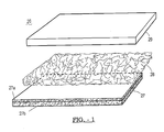
- FIG. 1 depicts the components of a composite 26 in accordance with the teachings of the present invention.
- a substrate 27 formed from a thermoformed epoxy, preferably a reinforced thermoformed epoxy made from a two part epoxy.
- reinforced it is meant that the epoxy resin includes fibers such as glass, synthetic fibers such as KEVLAR®, carbon fibers, metallic fibers, or particulate by way of non-limiting example.
- the fibers may be in the form of a woven mat, individual fibers in chopped or unchopped form, or combinations thereof.
- a particularly useful woven mat is a 3 x 3 twill carbon fiber reinforcement layer, preferably 3k twill 1161 woven fabric, available from Amoco.
- a commercially available two part epoxy substrate 27 which is useful in accordance with the teachings of the present invention, is made of West (brand) Epoxy 105 Resin, utilizing a 205 Fast Hardener from Gougeon Bros. Inc, Bay City Mi, with a 3 x 3 Twill Carbon Fiber reinforcement layer.
- the substrate 27 will be a multi-layer construction or designated by reference numerals 27a and 27b.
- the composite 26 also includes a porous layer 28, which is in the form of a fibrous mat. It is envisioned that it is possible that the reaction curing the epoxy resin phase of the substrate 27 will be an exothermic reaction. The heat produced by this reaction may assist in the formation of the bond between the thermoplastic layer 29 and the porous layer 28.
- the fibrous mat can be constructed of glass, steel, or natural and synthetic fibers, by way of non-limiting example. While the porosity of layer 28 may vary depending on the ultimate application for the composite material, the porosity must be sufficient to allow at least some of the thermoplastic material of layer 29 and/or substrate material of layer 27 penetrate the pores of the layer 28 such that direct bonding occurs between layers 27 and 29, respectively.
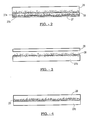
- porous layer 28 is generally a separate component prior to processing the composite, it should be recognized by those skilled in the art that the porous layer can be partially embedded into either the thermoplastic material or the substrate as shown in FIG. 3 prior to forming the composite.
- the third layer 29 of the composite is formed of a thermoplastic material having a static coefficient of friction of less than about 0.25 at 23°C as measured against chromium plated steel.
- the thermoplastic material is preferably ultra-high molecular weight polyethylene (UHMWPE) having a thickness between 0.2 mm and 10 cm.
- Ultra-high molecular weight polyethylenes useful in accordance with the teachings of the present invention are available from a number of commercial suppliers such Westlake Corporation of Lenni, PA. Particularly useful is Westlake's fabric backed, static-reduced UHMWPE.
- FIG. 2 is a cross-section of a composite formed from the above described components. More particularly, the illustrated composite includes a porous layer 28 impregnated by the cured epoxy resin of the substrate and the thermoplastic layer 29. While traditionally there is a significant amount of difficulty in bonding UHMWPE to other materials, and failure at the bond interface 18 would be expected as will be described in greater detail below, surprisingly testing to date has failed to show a failure along the UHMWPE/substrate interface 18.
- FIGS. 3 and 4 Shown in FIGS. 3 and 4 are alternative embodiments of the composite material wherein the substrate layer 27c is formed of steel or another metal. Disposed on the surface of the substrate is a porous layer 28.
- the porous layer 28 may also be formed from metallic fibers or formed by powder metallurgical techniques. As with the embodiment of FIG. 1 , the porous layer 28 can be joined to the metallic substrate 27c layer prior to formation of the composite by use of adhesives.
- FIGS. 5a-5e illustrate formation and processing of a composite material in accordance with the teachings of the present invention.
- a mold plate or tool 34 Disposed on a mold plate or tool 34 is uncured reinforced epoxy resin based substrate 27.
- a release film 35 is interposed between the substrate and the mold.
- a layer of porous material 28 is disposed on the uncured substrate 27 with a layer of thermoplastic material or UHMWPE 29 having a relatively low coefficient of friction disposed thereon.
- Another layer of release film 35 is optionally disposed over the thermoplastic layer.
- a vacuum is applied to the construct.
- the vacuum may be an integral part of the mold or optionally can be in the form of a vacuum bag 33 having a vacuum line 36 coupled thereto whereby the vacuum bag encapsulates the mold tool.
- the entire assembly is processed to produce the finished part as is shown in FIG. 5 .
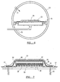
- FIG. 6 shows a typical autoclave assembly for use in an alternate method of formation of the current invention.
- the autoclave wall 50 which acts as a pressure vessel and insulator for the air within the autoclave assists in the curing of the epoxy and facilitates removal of air between the layers.
- a pressure inlet 51 Disposed within the autoclave wall 50 is a pressure inlet 51, which is used to bring pressurized air into the autoclave to assist in processing the construct 28.
- a vacuum outlet 52 for pulling gases out of the vacuum bag assembly 33 as described below.
- a mold base plate 54 over which the material is shaped.
- a flat base 54 is shown, but it is envisioned that the mold base plate 54 can take any shape necessary.
- Disposed on top of the mold base plate 54 is the construct 58, including substrate 27, porous layer 28, and UHMWPE layer 29, as previously described.
- a porous release film 35 which allows the material to be removed from the base plate 54 after processing.
- an amount of bleeder cloth 56 which functions to absorb excess epoxy ejected during the process.
- a pressure plate 57 Disposed between the pressure plate 57 and the construct 58 is a non-porous release film 59 which assists in the separation of the pressure plate 57 and the composite construct 58.
- the vacuum bag 33 is sealed to the mold plate by using a sealant 37. Vacuum outlets 52 are coupled to the cavity 60 formed by the vacuum bag 33. During the processing of the composite material, heat and pressure are applied in the autoclave and vacuum is drawn through the vacuum outlet port 52.
- FIGS. 8-25 represent components in the food production conveyor industry utilizing the broad teachings of the present invention.
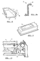
- FIGS. 8-10 represent a vibratory pan 72 for use in cereal production utilizing the composite material 26 of the present invention.
- Fig. 8a which is a magnified view of a cross section piece of the vibratory pan 72.
- the vibratory pan 72 includes a layer of static reduced UHMWPE, a plastic material which has been FDA approved for food contact, and eight layers of 3 X 3 twill carbon fiber reinforcement in a 2-part epoxy resin matrix.
- the static dissipation by the electrically conductive UHMWPE greatly reduces fine particle buildup on the surfaces of the vibratory pan 72 during food production.
- the vibratory pan 72 has a bottom horizontal surface 71 and coupled depending sides 73.
- reinforcing ribs 74 as shown in figure 9 can be incorporated into the composite structure.
- Vibratory pans 72 made of the material 26 further see a significant reduction in the amount of sanitation time needed.
- One particular benefit of the UHMWPE layer 29 in a vibratory pan 72, as used in cereal processing application, is the almost 100% elimination of sugar coatings and marbits dust. Furthermore, raisins and other dried fruits build up is greatly reduced.
- the elimination of fine particles in the vibratory pan 72 is a significant benefit to the food handling industry. Fine particles which often release after a significant build up cause bags to blow out or an excessive amount of fine particles to be in a product. Because of the static discharging capability of the UHMWPE layer 29, which is electrically grounded, metal detectors which are used to test the integrity of the food stream can be utilized more effectively.
- FIGS. 11 and 12 show coating drums 77 made with the composite material 26 in accordance with the present invention.
- the coating drum 77 includes a construction, which includes a layer of UHMWPE 29 on a reinforced composite substrate layer 27.
- the drum interior 78 includes a plurality of paddles 79 also having an exposed UHMWPE layer 29, which assist in the coating of food products.
- These drums are light weight and further show a benefit of having significantly reduced expansion or contraction due to the low coefficient of expansion of the composite. The reduced coefficient of expansion significantly aids in the line set up of the conveyor system.
- the coating drums 77 preferably have an interior UHMWPE layer 29 which is FDA approved in either a natural or anti-static grade.
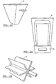
- FIG. 13 represents an elevator lift bucket 80 using the composite 26 of the present invention.
- the elevator lift bucket 80 made using the composite structure including a UHMWPE layer 29 and reinforced substrate layer 27, as illustrated in FIG. 13a , is much stronger than conventional polypropylene models.
- the end plates 81, 82 of the bucket 80 are removable in case there is a jam because of chain wear in the system. As such, the entire bucket 80 need not be thrown away and generally only the end plates 81 and 82 need be replaced.
- the exposed interior surface 83 of the bucket 80 is preferably a UHMWPE layer 29. Raisins, sugar coated cereals, marshmallows, and cracker fines do not build up. As cleaning solutions do not effect the material, sanitation time is greatly reduced over standard polypropylene elevator lift buckets 80.
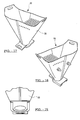
- FIGS. 14-16 represent scale hoppers 84 utilizing composite materials 26 of the current invention.
- Ishida-style scale hoppers 84 having doors 85 made from the composite material shown in FIG. 16a as including UHMWPE layer 29 and reinforced substrate 27 provide a number of benefits.
- One of which is a significant decrease in the amount of noise the product rushing through the hopper 84 produces. This is a significant ergonomic benefit for plant operations.
- FIGS. 17-19 represent blending hoppers 86, the housings of which are normally made of stainless steel.
- the hopper 86, and particularly the hopper housing 88, are made of the composite material 26 which prevents raisins, for example, from clumping together when being blended with other food products such as cereal flakes.
- the inherent nature of the blending hopper 86 normally leads to a significant amount of material build up and thus requires frequent cleaning. As with the other applications using the composite material of the present invention, there is a significant reduction of fines.
- FIGS. 20 and 21 represent the use of the composite material 26 in bagging hoppers 87. These hoppers 87 have shown significant resistance to stress cracks and resistance fines build up, particularly those resulting from sugar coated flakes which are particularly problematic in the cereal production industry.
- the bagging hoppers 87 made of this material represent a significant weight reduction and are easily cleaned and sterilized.
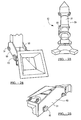
- FIG. 21 represents a bag hopper 87 having an integral regulator sleeve 91.
- FIG. 22 represents a static reduced UHMWPE NuCon demount rotary valve 90 using the composite material 26.
- the use of the static reduced UHMWPE components which are FDA approved greatly reduced fine particle build up within the valve. Also eliminated is the risk of static shock when workers come into contact with the components during production. As with the other applications, the weight of the UHMWPE coated components is greatly reduced when compared to stainless steel. Sanitation time is reduced as the UHMWPE is chemically resistant.
- FIGS. 23-25 represent a raisin let down transition 92 for the cereal industry using the composite material 26 to make the tube 61.
- these units were made of stainless steel and included two Teflon coated proximity sensors 94 similar to those shown.
- the sensing systems have proven to be ineffective.
- the sensors of prior art embodiments tend to require cleaning several times a day.
- the sensors tend to work better and require fewer cleanings.
- the food transporting portion of the let down transition is generally formed by a square tube 95. Furthermore, because of the polymer material of the current invention, proximity sensors are able to be positioned outside of the unit to allow access to the controls and eliminate problems associated with having the sensors within the production flow, which is necessary in metallic transitions.
- post processing may involve:
- the peel protective paper coating is pulled off of the UHMWPE, any surfaces needing touch-up are painted, the surfaces are then cleaned, and the composite is packed for shipment.
- the presence of heat from an exothermic curing reaction of the substrate 27 may assist in the bonding of the UHMWPE layer 29 to the porous layer 28. It is envisioned that heat from non-reaction sources may be applied during compression to assist the bonding of the thermoplastic layer 29 to the porous layer 28.
- collar assembly forming tube assembly, and rotating drum are formed using processes applicable for forming tubes.
- These tubes can have a layer of UHMWPE on both the interior and exterior surfaces of the component. The Formation of the forming tube is as follows:
- the process for forming the collar assembly is as follows:
- Generally flat components such as scale buckets and/or doors can also have a layer of UHMWPE on both the interior and exterior surfaces of the component.
- the formation of the Baseplate is as follows:
Landscapes
- Laminated Bodies (AREA)
Claims (21)
- Composite comprenant:une couche formée à partir d'un matériau époxy;une couche poreuse partiellement disposée dans ladite couche formée à partir d'un matériau d'époxy; etune couche thermoplastique d'UHMWPE, ayant un coefficient de frottement inférieur à environ 0,25 à 23°C et une épaisseur comprise entre 0,2 mm et 10 cm, qui est en contact avec ladite couche poreuse;après la jonction desdites couches, une portion de ladite couche thermoplastique d'UHMWPE pénétrant ladite couche poreuse de manière à être couplée directement à la couche dudit substrat formé à partir d'un matériau d'époxy.
- Composite selon la revendication 1, dans lequel après la jonction desdites couches, ladite couche poreuse est au moins partiellement noyée dans ledit thermoplastique d'UHMWPE.
- Composite selon la revendication 2, dans lequel ladite couche de substrat est formée à partir d'un matériau choisi dans le groupe consistant essentiellement en composite d'époxy renforcé, métal, composite d'époxy renforcé de carbone, composite d'époxy renforcé de fibre de verre, composite d'époxy renforcé de fibre synthétique et composite d'époxy renforcé de fibres de tissu tissé.
- Composite selon la revendication 2, dans lequel ladite couche poreuse est choisie dans un groupe consistant essentiellement en un mat fibreux, des fibres de verre, des fibres synthétiques et des fibres naturelles.
- Composite selon la revendication 1, dans lequel ledit composite est utilisé pour former un plateau vibrant.
- Composite selon la revendication 1, dans lequel ledit composite est utilisé pour former un dispositif d'ensachage.
- Procédé pour former un matériau composite, comprenant les étapes consistant à:fournir un substrat comprenant une couche formée à partir d'un matériau d'époxy;fournir une couche poreuse partiellement disposée dans ledit substrat;fournir une couche thermoplastique d'UHMWPE, ayant un coefficient de frottement inférieur à environ 0,25 à 23°C et une épaisseur comprise entre 0,2 mm et 10 cm, qui est en contact avec ladite couche poreuse; etappliquer une pression en présence de chaleur à la couche thermoplastique si bien que la couche thermoplastique pénètre partiellement la couche poreuse pour verrouiller mécaniquement la couche thermoplastique avec ladite couche poreuse et lier ladite couche thermoplastique directement au substrat à travers ladite couche poreuse.
- Procédé selon la revendication 7, dans lequel la liaison de ladite couche poreuse à ladite couche de substrat comprend l'inter-verrouillage mécanique de ladite couche poreuse à ladite couche de substrat.
- Procédé selon la revendication 7, dans lequel la fourniture d'une couche de substrat fournit une résine époxy thermodurcissable.
- Procédé selon la revendication 7, dans lequel la fourniture d'une couche poreuse fournit un mat de fibres poreux.
- Elément allongé pouvant être utilisé avec un système de convoyeur comprenant:un substrat comprenant une couche formée à partir d'un matériau d'époxy;une couche poreuse partiellement disposée dans ledit substrat; etune couche thermoplastique d'UHMWPE, ayant un coefficient de frottement inférieur à environ 0,25 à 23°C et une épaisseur comprise entre 0,2 mm et 10 cm, disposée sur ladite couche poreuse, après la jonction desdites couches, ladite couche poreuse est au moins partiellement disposée dans ladite couche thermoplastique d'UHMWPE et ladite couche thermoplastique d'UHMWPE est liée directement à la couche de substrat formée à partir d'un matériau d'époxy à travers ladite couche poreuse.
- Elément allongé selon la revendication 11, dans lequel ladite couche de substrat est choisie dans le groupe consistant essentiellement en composite d'époxy renforcé, composite d'époxy renforcé de carbone, composite d'époxy renforcé de fibre de verre, composite d'époxy renforcé de fibre synthétique et composite d'époxy renforcé de fibres de tissu tissé.
- Elément allongé selon la revendication 11, comprenant en outre une paire de parois latérales dépendantes, ladite couche thermoplastique étant disposée sur lesdites parois latérales.
- Elément allongé selon la revendication 11, dans lequel l'élément allongé est un plateau vibrant.
- Elément allongé selon la revendication 11, dans lequel ledit composite est utilisé pour former un dispositif d'ensachage.
- Glissoire pour un système de convoyeur comprenant:au moins un élément composite définissant une surface intérieure et extérieure;un substrat comprenant une couche formée à partir d'un matériau d'époxy;une couche poreuse partiellement disposée dans ledit substrat; etune couche thermoplastique d'UHMWPE, ayant un coefficient de frottement inférieur à environ 0,25 à 23°C et une épaisseur comprise entre 0,2 mm et 10 cm, qui est en contact avec ladite couche poreuse; la couche d'UHMWPE étant liée directement à la couche de substrat à travers ladite couche poreuse, ladite couche thermoplastique d'UHMWPE définissant ladite surface intérieure.
- Glissoire selon la revendication 16, dans lequel ladite couche de substrat est choisie dans le groupe consistant essentiellement en composite d'époxy renforcé, composite d'époxy renforcé de fibre de verre, composite d'époxy renforcé de fibre carbone et composite d'époxy renforcé de fibre synthétique.
- Glissoire selon la revendication 16, comprenant en outre une grille de tri.
- Glissoire selon la revendication 16, dans lequel le glissoire est un cylindre creux.
- Glissoire selon la revendication 19, dans lequel ledit cylindre est un tambour pouvant être entraîné en rotation.
- Glissoire selon la revendication 20, dans lequel ledit tambour comprend des palettes disposées sur ladite surface intérieure.
Applications Claiming Priority (3)
| Application Number | Priority Date | Filing Date | Title |
|---|---|---|---|
| US22513700P | 2000-08-14 | 2000-08-14 | |
| US225137P | 2000-08-14 | ||
| PCT/US2001/003561 WO2002014062A1 (fr) | 2000-08-14 | 2001-02-02 | Stratifie composite et son procede de production |
Publications (3)
| Publication Number | Publication Date |
|---|---|
| EP1409238A1 EP1409238A1 (fr) | 2004-04-21 |
| EP1409238A4 EP1409238A4 (fr) | 2004-04-21 |
| EP1409238B1 true EP1409238B1 (fr) | 2015-11-11 |
Family
ID=22843686
Family Applications (1)
| Application Number | Title | Priority Date | Filing Date |
|---|---|---|---|
| EP01906953.3A Expired - Lifetime EP1409238B1 (fr) | 2000-08-14 | 2001-02-02 | Stratifie composite et son procede de production |
Country Status (5)
| Country | Link |
|---|---|
| US (1) | US7273644B2 (fr) |
| EP (1) | EP1409238B1 (fr) |
| AU (1) | AU2001234794A1 (fr) |
| CA (1) | CA2430946C (fr) |
| WO (1) | WO2002014062A1 (fr) |
Families Citing this family (7)
| Publication number | Priority date | Publication date | Assignee | Title |
|---|---|---|---|---|
| DE10203123C1 (de) * | 2002-01-25 | 2003-02-06 | Sgl Acotec Gmbh | Verbundrohr aus einer PTFE-Innenschicht und einer Deckschicht aus einem faserverstärkten Kunststoff |
| US20040115477A1 (en) * | 2002-12-12 | 2004-06-17 | Bruce Nesbitt | Coating reinforcing underlayment and method of manufacturing same |
| WO2005005198A2 (fr) | 2003-07-01 | 2005-01-20 | Collins & Aikman Products Co. | Articles multicouche absorbants acoustiques et procedes de production de ceux-ci |
| TW200726344A (en) * | 2005-12-30 | 2007-07-01 | Epistar Corp | Hybrid composite material substrate |
| US8287791B2 (en) * | 2009-12-23 | 2012-10-16 | Tema Isenmann, Inc. | Process of producing a removable magnetic liner |
| US9283700B2 (en) * | 2009-12-23 | 2016-03-15 | Tema Isenmann, Inc. | Removable magnetic liner and screening media, and processes of production, installation, and use thereof |
| US20150140252A1 (en) * | 2010-09-28 | 2015-05-21 | 3Form, Inc. | Variable interlayer laminate panels and methods of forming the same |
Family Cites Families (12)
| Publication number | Priority date | Publication date | Assignee | Title |
|---|---|---|---|---|
| US3616140A (en) * | 1968-05-17 | 1971-10-26 | Brunswick Corp | Rain erosion resistant material for airborne vehicle |
| JPS5931145A (ja) * | 1982-08-12 | 1984-02-20 | 旭有機材工業株式会社 | 超高分子量ポリエチレン積層体 |
| US4425396A (en) * | 1982-09-28 | 1984-01-10 | The B. F. Goodrich Company | Insulative panel |
| JPS60155428A (ja) * | 1984-01-25 | 1985-08-15 | Nippon Petrochem Co Ltd | 積層シ−トもしくは積層フイルムの製造方法 |
| US4944974A (en) * | 1984-10-24 | 1990-07-31 | Zachariades Anagnostis E | Composite structures of ultra-high-molecular-weight polymers, such as ultra-high-molecular-weight polyethylene products, and method of producing such structures |
| US5160472A (en) * | 1984-10-24 | 1992-11-03 | Zachariades Anagnostis E | Method of producing composite structures of ultra-high-molecular-weight polymers, such as ultra-high-molecular-weight polyethylene products |
| JPS62204938A (ja) * | 1986-03-06 | 1987-09-09 | 田辺 稔幸 | 超高分子ポリオレフイン系樹脂と高分子ポリオレフイン系樹脂の多層シ−ト |
| CA2023352A1 (fr) * | 1989-08-21 | 1991-02-22 | Raymond Charles Srail | Melange de polyethylene a masse moleculaire extremement elevee, moule par compression, retardateur de flamme et a grande resistance au choc |
| US5098778A (en) * | 1990-04-24 | 1992-03-24 | General Electric Company | Plastic based laminates comprising outer fiber-reinforced thermoset sheets, lofted fiber-reinforced thermoplastic sheets and a foam core layer |
| JPH082623B2 (ja) * | 1990-08-23 | 1996-01-17 | ソマール株式会社 | 超高分子量ポリエチレン複合シート及びその製造方法 |
| US6196370B1 (en) * | 1998-03-27 | 2001-03-06 | Tonoga Limited | Package conveying surface with liner |
| JP2000177054A (ja) * | 1998-12-17 | 2000-06-27 | Nisshin Steel Co Ltd | 衝撃吸収性及び摺動性に優れた積層鋼板 |
-
2001
- 2001-02-02 CA CA002430946A patent/CA2430946C/fr not_active Expired - Fee Related
- 2001-02-02 WO PCT/US2001/003561 patent/WO2002014062A1/fr not_active Ceased
- 2001-02-02 EP EP01906953.3A patent/EP1409238B1/fr not_active Expired - Lifetime
- 2001-02-02 AU AU2001234794A patent/AU2001234794A1/en not_active Abandoned
-
2003
- 2003-02-05 US US10/358,738 patent/US7273644B2/en not_active Expired - Lifetime
Also Published As
| Publication number | Publication date |
|---|---|
| US7273644B2 (en) | 2007-09-25 |
| US20030124290A1 (en) | 2003-07-03 |
| AU2001234794A1 (en) | 2002-02-25 |
| CA2430946C (fr) | 2009-11-10 |
| EP1409238A1 (fr) | 2004-04-21 |
| EP1409238A4 (fr) | 2004-04-21 |
| CA2430946A1 (fr) | 2002-02-21 |
| WO2002014062A1 (fr) | 2002-02-21 |
Similar Documents
| Publication | Publication Date | Title |
|---|---|---|
| US7740925B2 (en) | Composite laminate and method of producing a composite laminate | |
| US10596730B2 (en) | Hybrid lay-up mold | |
| JP5840687B2 (ja) | 複合材と金属のジョイントを有する複合構造物およびその作製方法 | |
| EP1281504B1 (fr) | Procédé pour fabriquer une structure | |
| JP6490340B2 (ja) | 短繊維材料を含む空隙充填材を有する複合構造を作製する方法及びシステム | |
| AU761069C (en) | Moulding materials | |
| EP1409238B1 (fr) | Stratifie composite et son procede de production | |
| EP2070694B1 (fr) | Panneau composite et son procédé de fabrication | |
| CA2857783A1 (fr) | Composite lamine de remplissage de rayons avec element de remplissage de forme geometrique et procede de formation de celui-ci | |
| US20140134383A1 (en) | Method for local reinforcement of a composite fiber reinforced panel and panel obtained using said method | |
| CA2404982C (fr) | Structure de confinement de cabine de revetement en poudre | |
| US20160082710A1 (en) | Method and system for compacting composite part layup utilizing a single release film layer | |
| EP3453525B1 (fr) | Procédé et dispositif pour fabriquer des panneaux sandwich raidis en matériau composite | |
| US5738741A (en) | Pre-fabricated vacuum bag and vacuum bag process to externally reinforce structural members with advanced composites | |
| WO2008137952A2 (fr) | Couche respirante de microparticules servant à la fabrication de pièces composites | |
| US9034137B2 (en) | In-situ, multi-stage debulk, compaction, and single stage curing of thick composite repair laminates | |
| CN109676974A (zh) | 一种修复碳纤维横杆的方法 | |
| EP1378338A1 (fr) | Méthode et dispositif pour la production de produits composites utilisant un moule fermé comprenant un revêtement interieur et revêtement interieur de moule pour leur mise en oeuvre | |
| US20100189939A1 (en) | Fiber reinforced article and method of making same | |
| JPH09242212A (ja) | 吸音材およびその製法 |
Legal Events
| Date | Code | Title | Description |
|---|---|---|---|
| PUAI | Public reference made under article 153(3) epc to a published international application that has entered the european phase |
Free format text: ORIGINAL CODE: 0009012 |
|
| 17P | Request for examination filed |
Effective date: 20030612 |
|
| A4 | Supplementary search report drawn up and despatched |
Effective date: 20040206 |
|
| AK | Designated contracting states |
Kind code of ref document: A1 Designated state(s): AT BE CH CY DE DK ES FI FR GB GR IE IT LI LU MC NL PT SE TR |
|
| AX | Request for extension of the european patent |
Extension state: AL LT LV MK RO SI |
|
| 17Q | First examination report despatched |
Effective date: 20050302 |
|
| GRAP | Despatch of communication of intention to grant a patent |
Free format text: ORIGINAL CODE: EPIDOSNIGR1 |
|
| INTG | Intention to grant announced |
Effective date: 20150601 |
|
| GRAS | Grant fee paid |
Free format text: ORIGINAL CODE: EPIDOSNIGR3 |
|
| GRAA | (expected) grant |
Free format text: ORIGINAL CODE: 0009210 |
|
| AK | Designated contracting states |
Kind code of ref document: B1 Designated state(s): AT BE CH CY DE DK ES FI FR GB GR IE IT LI LU MC NL PT SE TR |
|
| REG | Reference to a national code |
Ref country code: GB Ref legal event code: FG4D |
|
| REG | Reference to a national code |
Ref country code: CH Ref legal event code: EP |
|
| REG | Reference to a national code |
Ref country code: IE Ref legal event code: FG4D |
|
| REG | Reference to a national code |
Ref country code: AT Ref legal event code: REF Ref document number: 760234 Country of ref document: AT Kind code of ref document: T Effective date: 20151215 |
|
| REG | Reference to a national code |
Ref country code: DE Ref legal event code: R096 Ref document number: 60149662 Country of ref document: DE |
|
| REG | Reference to a national code |
Ref country code: FR Ref legal event code: PLFP Year of fee payment: 16 |
|
| REG | Reference to a national code |
Ref country code: NL Ref legal event code: MP Effective date: 20160211 |
|
| REG | Reference to a national code |
Ref country code: AT Ref legal event code: MK05 Ref document number: 760234 Country of ref document: AT Kind code of ref document: T Effective date: 20151111 |
|
| PG25 | Lapsed in a contracting state [announced via postgrant information from national office to epo] |
Ref country code: ES Free format text: LAPSE BECAUSE OF FAILURE TO SUBMIT A TRANSLATION OF THE DESCRIPTION OR TO PAY THE FEE WITHIN THE PRESCRIBED TIME-LIMIT Effective date: 20151111 Ref country code: NL Free format text: LAPSE BECAUSE OF FAILURE TO SUBMIT A TRANSLATION OF THE DESCRIPTION OR TO PAY THE FEE WITHIN THE PRESCRIBED TIME-LIMIT Effective date: 20151111 |
|
| PG25 | Lapsed in a contracting state [announced via postgrant information from national office to epo] |
Ref country code: AT Free format text: LAPSE BECAUSE OF FAILURE TO SUBMIT A TRANSLATION OF THE DESCRIPTION OR TO PAY THE FEE WITHIN THE PRESCRIBED TIME-LIMIT Effective date: 20151111 Ref country code: FI Free format text: LAPSE BECAUSE OF FAILURE TO SUBMIT A TRANSLATION OF THE DESCRIPTION OR TO PAY THE FEE WITHIN THE PRESCRIBED TIME-LIMIT Effective date: 20151111 Ref country code: GR Free format text: LAPSE BECAUSE OF FAILURE TO SUBMIT A TRANSLATION OF THE DESCRIPTION OR TO PAY THE FEE WITHIN THE PRESCRIBED TIME-LIMIT Effective date: 20160212 Ref country code: BE Free format text: LAPSE BECAUSE OF NON-PAYMENT OF DUE FEES Effective date: 20160229 Ref country code: PT Free format text: LAPSE BECAUSE OF FAILURE TO SUBMIT A TRANSLATION OF THE DESCRIPTION OR TO PAY THE FEE WITHIN THE PRESCRIBED TIME-LIMIT Effective date: 20160311 Ref country code: SE Free format text: LAPSE BECAUSE OF FAILURE TO SUBMIT A TRANSLATION OF THE DESCRIPTION OR TO PAY THE FEE WITHIN THE PRESCRIBED TIME-LIMIT Effective date: 20151111 |
|
| REG | Reference to a national code |
Ref country code: DE Ref legal event code: R097 Ref document number: 60149662 Country of ref document: DE |
|
| PG25 | Lapsed in a contracting state [announced via postgrant information from national office to epo] |
Ref country code: DK Free format text: LAPSE BECAUSE OF FAILURE TO SUBMIT A TRANSLATION OF THE DESCRIPTION OR TO PAY THE FEE WITHIN THE PRESCRIBED TIME-LIMIT Effective date: 20151111 |
|
| PLBE | No opposition filed within time limit |
Free format text: ORIGINAL CODE: 0009261 |
|
| STAA | Information on the status of an ep patent application or granted ep patent |
Free format text: STATUS: NO OPPOSITION FILED WITHIN TIME LIMIT |
|
| PG25 | Lapsed in a contracting state [announced via postgrant information from national office to epo] |
Ref country code: LU Free format text: LAPSE BECAUSE OF FAILURE TO SUBMIT A TRANSLATION OF THE DESCRIPTION OR TO PAY THE FEE WITHIN THE PRESCRIBED TIME-LIMIT Effective date: 20160202 Ref country code: MC Free format text: LAPSE BECAUSE OF FAILURE TO SUBMIT A TRANSLATION OF THE DESCRIPTION OR TO PAY THE FEE WITHIN THE PRESCRIBED TIME-LIMIT Effective date: 20151111 |
|
| REG | Reference to a national code |
Ref country code: CH Ref legal event code: PL |
|
| 26N | No opposition filed |
Effective date: 20160812 |
|
| PG25 | Lapsed in a contracting state [announced via postgrant information from national office to epo] |
Ref country code: LI Free format text: LAPSE BECAUSE OF NON-PAYMENT OF DUE FEES Effective date: 20160229 Ref country code: CH Free format text: LAPSE BECAUSE OF NON-PAYMENT OF DUE FEES Effective date: 20160229 |
|
| REG | Reference to a national code |
Ref country code: IE Ref legal event code: MM4A |
|
| PG25 | Lapsed in a contracting state [announced via postgrant information from national office to epo] |
Ref country code: BE Free format text: LAPSE BECAUSE OF FAILURE TO SUBMIT A TRANSLATION OF THE DESCRIPTION OR TO PAY THE FEE WITHIN THE PRESCRIBED TIME-LIMIT Effective date: 20151111 |
|
| PG25 | Lapsed in a contracting state [announced via postgrant information from national office to epo] |
Ref country code: IE Free format text: LAPSE BECAUSE OF NON-PAYMENT OF DUE FEES Effective date: 20160202 |
|
| REG | Reference to a national code |
Ref country code: FR Ref legal event code: PLFP Year of fee payment: 17 |
|
| REG | Reference to a national code |
Ref country code: FR Ref legal event code: PLFP Year of fee payment: 18 |
|
| PGFP | Annual fee paid to national office [announced via postgrant information from national office to epo] |
Ref country code: DE Payment date: 20180227 Year of fee payment: 18 Ref country code: GB Payment date: 20180227 Year of fee payment: 18 |
|
| PG25 | Lapsed in a contracting state [announced via postgrant information from national office to epo] |
Ref country code: CY Free format text: LAPSE BECAUSE OF FAILURE TO SUBMIT A TRANSLATION OF THE DESCRIPTION OR TO PAY THE FEE WITHIN THE PRESCRIBED TIME-LIMIT Effective date: 20151111 |
|
| PGFP | Annual fee paid to national office [announced via postgrant information from national office to epo] |
Ref country code: FR Payment date: 20180227 Year of fee payment: 18 Ref country code: IT Payment date: 20180222 Year of fee payment: 18 |
|
| PG25 | Lapsed in a contracting state [announced via postgrant information from national office to epo] |
Ref country code: TR Free format text: LAPSE BECAUSE OF FAILURE TO SUBMIT A TRANSLATION OF THE DESCRIPTION OR TO PAY THE FEE WITHIN THE PRESCRIBED TIME-LIMIT Effective date: 20151111 |
|
| REG | Reference to a national code |
Ref country code: DE Ref legal event code: R119 Ref document number: 60149662 Country of ref document: DE |
|
| GBPC | Gb: european patent ceased through non-payment of renewal fee |
Effective date: 20190202 |
|
| PG25 | Lapsed in a contracting state [announced via postgrant information from national office to epo] |
Ref country code: GB Free format text: LAPSE BECAUSE OF NON-PAYMENT OF DUE FEES Effective date: 20190202 Ref country code: DE Free format text: LAPSE BECAUSE OF NON-PAYMENT OF DUE FEES Effective date: 20190903 |
|
| PG25 | Lapsed in a contracting state [announced via postgrant information from national office to epo] |
Ref country code: IT Free format text: LAPSE BECAUSE OF NON-PAYMENT OF DUE FEES Effective date: 20190202 Ref country code: FR Free format text: LAPSE BECAUSE OF NON-PAYMENT OF DUE FEES Effective date: 20190228 |