EP1410007B1 - Methode und gerät zur messung der eigenschaften von flüssigkeiten - Google Patents
Methode und gerät zur messung der eigenschaften von flüssigkeiten Download PDFInfo
- Publication number
- EP1410007B1 EP1410007B1 EP00983454A EP00983454A EP1410007B1 EP 1410007 B1 EP1410007 B1 EP 1410007B1 EP 00983454 A EP00983454 A EP 00983454A EP 00983454 A EP00983454 A EP 00983454A EP 1410007 B1 EP1410007 B1 EP 1410007B1
- Authority
- EP
- European Patent Office
- Prior art keywords
- acoustic
- liquid
- drop
- sample
- acoustic energy
- Prior art date
- Legal status (The legal status is an assumption and is not a legal conclusion. Google has not performed a legal analysis and makes no representation as to the accuracy of the status listed.)
- Expired - Lifetime
Links
- 239000007788 liquid Substances 0.000 title claims abstract description 77
- 238000000034 method Methods 0.000 title claims abstract description 15
- 238000005259 measurement Methods 0.000 claims abstract description 16
- 230000003993 interaction Effects 0.000 claims abstract description 11
- 238000004458 analytical method Methods 0.000 claims description 9
- 230000010355 oscillation Effects 0.000 claims description 4
- 230000000694 effects Effects 0.000 claims description 3
- 230000026683 transduction Effects 0.000 claims description 3
- 238000010361 transduction Methods 0.000 claims description 3
- 230000005855 radiation Effects 0.000 claims description 2
- 230000002730 additional effect Effects 0.000 abstract 1
- 239000000523 sample Substances 0.000 description 9
- 239000012530 fluid Substances 0.000 description 7
- 235000015095 lager Nutrition 0.000 description 4
- 239000000463 material Substances 0.000 description 4
- 230000015572 biosynthetic process Effects 0.000 description 3
- 239000000203 mixture Substances 0.000 description 3
- 239000007787 solid Substances 0.000 description 3
- 230000003068 static effect Effects 0.000 description 3
- 239000000126 substance Substances 0.000 description 3
- 229910001369 Brass Inorganic materials 0.000 description 2
- 239000010951 brass Substances 0.000 description 2
- 238000012512 characterization method Methods 0.000 description 2
- 238000001514 detection method Methods 0.000 description 2
- 235000005911 diet Nutrition 0.000 description 2
- 230000037213 diet Effects 0.000 description 2
- 238000003908 quality control method Methods 0.000 description 2
- 235000014214 soft drink Nutrition 0.000 description 2
- 239000000725 suspension Substances 0.000 description 2
- 235000013405 beer Nutrition 0.000 description 1
- 239000012867 bioactive agent Substances 0.000 description 1
- 230000000740 bleeding effect Effects 0.000 description 1
- 238000006243 chemical reaction Methods 0.000 description 1
- 230000008878 coupling Effects 0.000 description 1
- 238000010168 coupling process Methods 0.000 description 1
- 238000005859 coupling reaction Methods 0.000 description 1
- 238000010586 diagram Methods 0.000 description 1
- 230000007613 environmental effect Effects 0.000 description 1
- 238000011010 flushing procedure Methods 0.000 description 1
- 238000004374 forensic analysis Methods 0.000 description 1
- 238000009472 formulation Methods 0.000 description 1
- 239000007789 gas Substances 0.000 description 1
- 230000005484 gravity Effects 0.000 description 1
- 230000003287 optical effect Effects 0.000 description 1
- 239000012857 radioactive material Substances 0.000 description 1
- 241000894007 species Species 0.000 description 1
- 238000003786 synthesis reaction Methods 0.000 description 1
- 239000008399 tap water Substances 0.000 description 1
- 235000020679 tap water Nutrition 0.000 description 1
- 238000009736 wetting Methods 0.000 description 1
Images

Classifications
-
- G—PHYSICS
- G01—MEASURING; TESTING
- G01N—INVESTIGATING OR ANALYSING MATERIALS BY DETERMINING THEIR CHEMICAL OR PHYSICAL PROPERTIES
- G01N29/00—Investigating or analysing materials by the use of ultrasonic, sonic or infrasonic waves; Visualisation of the interior of objects by transmitting ultrasonic or sonic waves through the object
- G01N29/02—Analysing fluids
-
- G—PHYSICS
- G01—MEASURING; TESTING
- G01N—INVESTIGATING OR ANALYSING MATERIALS BY DETERMINING THEIR CHEMICAL OR PHYSICAL PROPERTIES
- G01N29/00—Investigating or analysing materials by the use of ultrasonic, sonic or infrasonic waves; Visualisation of the interior of objects by transmitting ultrasonic or sonic waves through the object
- G01N29/22—Details, e.g. general constructional or apparatus details
- G01N29/24—Probes
- G01N29/2462—Probes with waveguides, e.g. SAW devices
-
- G—PHYSICS
- G01—MEASURING; TESTING
- G01N—INVESTIGATING OR ANALYSING MATERIALS BY DETERMINING THEIR CHEMICAL OR PHYSICAL PROPERTIES
- G01N2291/00—Indexing codes associated with group G01N29/00
- G01N2291/02—Indexing codes associated with the analysed material
- G01N2291/028—Material parameters
- G01N2291/02818—Density, viscosity
Definitions
- This invention relates to an apparatus and method for measuring a property of a liquid. More particularly, it relates to the characterisation of liquids by obtaining fingerprints for the liquids, from which various properties can be derived.
- the invention also has as its aim the provision of an improved technique for use in forensic analysis of liquids.
- the invention further provides a method for measuring a property of a liquid as described in claim 22.
- the liquid which is in the form of a drop, may be a pure liquid, a mixture of liquids, a solution of a solid substance, a suspension of a solid within a liquid or a colloidal suspension, and the term "liquid" is used herein to signify all of these possibilities.
- drop is defined as the interface that is formed between a liquid and any other material or materials, such as a solid, gas or liquid, under the force of the surface tension of the interface usually, but not always, combined with the force of gravity, acting on a particular geometrical arrangement of said liquid and materials.
- the drop can be formed using bioactive agents or radioactive material.
- the drop can undergo one or more phase changes during or at a particular point in its growth cycle, and it can be contaminated by, or dissolved, or evaporated into a surrounding medium.
- Acoustic energy may be launched at the liquid sample from one or more sources, and the signal produced by the interaction with the sample can be obtained by various methods.
- One method is by examination of the loading effect on the driving signal to the acoustic source(s).
- a second is by comparing the driving signal to the modulated signal received by one or more detectors.
- the formation of the drop can take place directly upon an acoustic source or at the end of an acoustic guide attached to a source and/or a detector. Both configurations will henceforth be referred to as an "acoustic drop head".
- the drop head can be arranged to form either pendant or sessile drops.
- the drop formed at the end of the acoustic drop head can be analysed dynamically during its growth and release cycle, where one or more of a succession of drops are allowed to drip from the end of the acoustic drop head.
- one may analyse small volumes, or continuously monitor a liquid by bleeding off sample droplets for analysis.
- the liquid may also be allowed to evaporate from the drop formed under both static or dynamic drop conditions.
- the acoustic energy may be any acoustic radiation that can be coupled into the drop, and it can be pulsed, continuous, varying in frequency, amplitude or phase or otherwise modulated to facilitate the particular analysis being performed.
- the acoustic energy can be coupled directly into the drop using the acoustic drop head, which is in direct contact with the test liquid or alternatively it can be launched at the unattached surface of the drop through a medium of different acoustic impedance. In such a case one may monitor two or more signals-one is the signal that penetrates the drop, and the other is based on the acoustic field set up immediately outside of the drop.
- the source transducer may also act as the detector transducer.
- the signal related to the interaction of the acoustic energy and the liquid sample can be measured using an acoustic transduction measurement system. Any change in the driving signal from the acoustic radiator and the modulated signal is then used to deduce properties relating to the liquid under examination.
- the changes in the electrical driving signal referred to above may arise from variations in the acoustic impedance or geometry of the test liquid, thereby "loading" the signal produced by the source transducer. Changes in the acoustic signal may affect amplitude, phase, frequency, reverberation time, harmonics etc.
- the invention can be used to measure indirectly the following properties of a liquid:
- test liquid can be determined, such as the concentration level of other species contained within the liquid.
- the acoustic energy may be optimised in terms of frequency and power to set the drop of liquid into oscillation.
- Devices that monitor the oscillation of the drop that is energised in this fashion and simultaneously or subsequently monitor the drop by its acoustic signal as described above are within the scope of this invention.
- the invention includes the acoustic analysis of drops that are stimulated into oscillation or movement by any other means, such as mechanical energy, acoustic energy, an external force, thermal energy or as the result of a chemical or biological reaction.
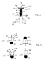
- an acoustic drop head 10 includes a cylindrical body 12 orientated with its axis substantially vertical.
- the body 12 has a concave lower surface 14 and a central axial bore 16 opening onto the surface 14.
- a liquid sample is delivered to the acoustic drop head via a tube 18 communicating with the bore 16, so that the liquid forms a pendant drop 20.
- the delivery of the liquid can be via syringe, pump or using a constant head of pressure, e.g. from a reservoir.
- the drop 20 may be static or it may be one of a succession of drops falling intermittently from the body 12.
- the bore 16 in the body 12 can be in any position provided there is a route to the drop-forming surface 14.
- the cross-sectional profile of the drop-forming surface 14 is contoured to ensure repeatable drop shapes and drop dimensions.
- the drop head 10 also includes a disc 22 at the top of, and having a greater diameter than, the body 12.
- the disc 22 is in intimate contact with, or is integral with, the body 12, and provides support for an acoustic source 24 and an acoustic detector 26.
- acoustic energy from the source 24 is coupled into the drop head 10 and travels through the body 12 and into the drop 20.
- the combination of drop head shape and drop geometry modulates the acoustic signal which is then monitored by the detector 26 to provide a corresponding signal.
- the lower end of body 12 is disposed coaxially within the upper end of a vertical tube 28, the latter having various side branches A to E which may be normal to the axis of the tube (branches A, C, E) or inclined thereto (branches B, D).
- the acoustic energy from a further source 30 (which can be positioned at the end of branch A or B) is used to couple energy both into the drop 20 and into the medium surrounding it.
- the modulated signal can then be detected by a second detector 32 located at any of branches C, D or E.
- the driving signal to the acoustic sources 24, 30 is also monitored as this can be modulated by the geometry of the drop 20.
- Detector 32 can also be used to determine the acoustic energy radiating out of the drop from source 24.
- acoustic sources each disposed, like the source 26, on the drop head 10 itself or, like the source 30, spaced therefrom, and also one or more acoustic detectors likewise disposed on the drop head or spaced therefrom.
- the drive frequency to the acoustic source(s) may be varied over a wide range, from tens of kilohertz to a few megahertz.
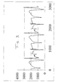
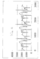
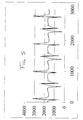
- the electrical signal from the detector(s) is then plotted against time to produce a graph called a tensiogram.
- the features in the tensiogram are then used to determine the properties of the liquid.
- Figs. 2(a) to 2(d) illustrate alternative arrangements both for launching acoustic energy at the drop and also the positioning of detectors.
- the body 12 of the drop head is generally in the form of a truncated cone, thereby dispensing with the need for the disc 22 ( Fig. 1).
- Fig. 2(b) shows the same arrangement inverted to form a sessile drop 20.
- Fig. 2(c) shows the source 24 and detector 26 on opposite sides of the body 12, while Fig. 2(d) uses a combined acoustic source/detector 34.
- the drop heads of Figs. 2(c) and 2(d) may also be inverted to produce sessile drops.
- inventions of the device include those where the foregoing acoustic method of analysis of a liquid is combined with other methods, such as optical analysis and capacitance-based techniques that have been described elsewhere in work published by the present applicants.
- the invention can be used both for measuring the mechanical and chemical properties of a liquid as detailed above, but also for identification of an unknown liquid. Examples of applications of such measurements will include on-line quality control measurements, detection of fake materials, biomedical fluid measurements, and reverse synthesis of particular formulations, as well as any other area where measurements on liquids are involved.
- the acoustic drop head used in this Example was designed to produce pendant drops using the configuration in Figure 1 (with the omission of vertical tube 28 and its appendages) which was manufactured out of a single section of brass. It was machined to produce a disc section at the top (25mm in diameter and 1.5mm thick) and a cylindrical shaft at the bottom (9mm in diameter and 30mm in length). A domed recess was machined into the bottom end of the cylindrical shaft to ensure proper wetting of the drop formation surface.
- a 2mm diameter hole which acted as a fluid delivery passageway was drilled through the axis of the probe head from the top of the disk to the bottom of the shaft.
- Two ultrasonic transducers (10mm in diameter and 1mm thick with an operating range from 20KHz to 1MHz) were soldered to the disk section by one of their metallised end faces.
- the centres of the transducers were 6.5mm from the disk axis and they were aligned such that the axes of both transducers and the fluid passageway were parallel and coplanar. Since the end face of each transducer was soldered directly to the brass disk this not only provided a good acoustic coupling but also provided a common electrical ground contact.
- Test liquid was poured into a constant head tank, which then flowed through 2mm plastic tubing (with a 0.9mm bore) to the acoustic drop head.
- the plastic tube was inserted into the fluid passageway of the probe head to the depth of 5mm to provide a fluid tight connection.
- the remaining face/electrical contact of the source transducer was soldered to a lead connected to a Farnell signal generator which had a frequency range from DC to 1MHz.
- the remaining face/electrical contact surface of the detector was used as an input to an op-amp where the signal was both amplified and rectified.
- the resulting DC signal was then applied to a 12 bit ADC to permit data logging.
- test liquids were degassed and allowed to reach room temperature before being poured in to the header tank. Between each test tap water was flushed through the system. After flushing, test liquid was allowed to flow until equilibrium in the system was reached.
- This particular embodiment of this device was operated at a frequency of 518,609 Hz and was used to test a number of liquids and liquid mixtures. It was found that the device output was extremely sensitive to variations in drop head geometry, orientation, temperature, ultrasonic frequency and fluid flow rate, so close environmental control and controlled fluid delivery is required to achieve reproducible results.
- Figures 3 and 4 show sample results obtained for the two cola drinks Coca Cola (Trade Mark) and Diet Pepsi (Trade Mark) respectively.
- the x and y axes are plotted with arbitrary units here, but by way of scaling, a single drop took approximately 110 seconds to form.
- the plots are both heavily featured, which is helpful for the purposes of characterisation, since a greater number of features means that there is more scope for variation from one liquid to another.
- Figures 5 and 6 show patterns which are generally different to those of Figs. 3 and 4 , but are in some ways similar to one another, and are perhaps indicative of a "lager" profile. However, the relative depth and position of the peaks and troughs is quite different between Figs. 5 and 6 , with some peaks that are present in the Hofmeister plot being absent in the corresponding plot for Heineken.
Landscapes
- Physics & Mathematics (AREA)
- Biochemistry (AREA)
- Health & Medical Sciences (AREA)
- Life Sciences & Earth Sciences (AREA)
- Chemical & Material Sciences (AREA)
- Analytical Chemistry (AREA)
- General Health & Medical Sciences (AREA)
- General Physics & Mathematics (AREA)
- Immunology (AREA)
- Pathology (AREA)
- Acoustics & Sound (AREA)
- Investigating Or Analyzing Materials By The Use Of Ultrasonic Waves (AREA)
- Investigating Or Analyzing Non-Biological Materials By The Use Of Chemical Means (AREA)
Claims (21)
- Vorrichtung (10) zur Verwendung bei der Messung einer Eigenschaft einer Flüssigkeit, die Folgendes umfasst: Mittel (24, 34) zum Richten von Schallenergie auf eine Probe der Flüssigkeit, Mittel (26, 34) zum Herleiten eines mit der Wechselwirkung der Schallenergie mit der Flüssigkeitsprobe zusammenhängenden Signals und Mittel zum Bilden der Flüssigkeitsprobe in der Form eines Tropfens (20),
wobei die genannte Vorrichtung dazu angeordnet ist, den genannten Tropfen während einer Änderung des Tropfenvolumens dynamisch zu analysieren, wodurch die Vorrichtung dazu angeordnet ist, eine charakteristische Messung der Eigenschaften der Flüssigkeit über einen Bereich von Volumen, basierend auf verschiedenen Schallenergie-Eingangsparametern bereitzustellen. - Vorrichtung nach Anspruch 1, wobei die Vorrichtung dazu angeordnet ist, den Tropfen direkt auf dem Mittel zum Richten von Schallenergie auf die Probe zu bilden.
- Vorrichtung nach Anspruch 2, wobei das Mittel zum Richten von Schallenergie eine Schallquelle umfasst.
- Vorrichtung nach Anspruch 2, wobei das Mittel zum Richten von Schallenergie einen an einer Schallquelle angebrachten Schallleiter umfasst, wobei die Vorrichtung dazu angeordnet ist, den Tropfen auf einem Ende des Schallleiters zu bilden.
- Vorrichtung nach Anspruch 1, wobei das Mittel zum Herleiten eines mit der Wechselwirkung der Schallenergie mit der Flüssigkeitsprobe zusammenhängenden Signals einen Schalldetektor umfasst und wobei die Vorrichtung dazu angeordnet ist, den Tropfen direkt auf dem Detektor zu bilden.
- Vorrichtung nach Anspruch 1, wobei das Mittel zum Herleiten eines mit der Wechselwirkung der Schallenergie mit der Flüssigkeitsprobe zusammenhängenden Signals einen Schalldetektor mit einem daran angebrachten Schallleiter umfasst und wobei die Vorrichtung dazu angeordnet ist, den Tropfen direkt auf einem Ende des Leiters zu bilden.
- Vorrichtung nach einem der Ansprüche 1-6, wobei die Vorrichtung dazu angeordnet ist, die Flüssigkeitsprobe hängende Tropfen bilden zu lassen.
- Vorrichtung nach einem der Ansprüche 1-6, wobei die Vorrichtung dazu angeordnet ist, die Flüssigkeitsprobe liegende Tropfen bilden zu lassen.
- Vorrichtung nach einem der vorangehenden Ansprüche, wobei das Mittel zum Richten von Schallenergie mehrere Schallquellen umfasst.
- Vorrichtung nach Anspruch 9, wobei ein Treibersignal von dem Mittel (24, 34) zum Richten von Schallenergie auf eine Probe der Flüssigkeit bereitgestellt wird und wobei ein Lasteffekt auf dem Treibersignal gebildet wird, und wobei die Vorrichtung dazu angeordnet ist, das durch die Wechselwirkung mit der Probe erzeugte Signal durch Untersuchen des Lasteffekts auf das Treibersignal an die Schallquellen zu erhalten.
- Vorrichtung nach einem der vorangehenden Ansprüche, wobei die Vorrichtung weiter einen oder mehrere Detektoren umfasst und wobei die Vorrichtung dazu angeordnet ist, das durch die Wechselwirkung mit der Probe erzeugte Signal durch Vergleichen eines von dem genannten Mittel (24, 34) zum Richten von Schallenergie auf eine Probe der Flüssigkeit erzeugten Treibersignals mit einem modulierten Signal, das von dem einen beziehungsweise den mehreren Detektoren empfangen wird, zu erhalten.
- Vorrichtung nach Anspruch 1, wobei die Vorrichtung einen akustischen Tropfenkopf umfasst und wobei die Vorrichtung dazu angeordnet ist, zuzulassen, dass der Flüssigkeitstropfen einen Wachstums- und Freisetzungszyklus durchläuft, wobei zugelassen wird, dass einer oder mehrere einer Folge von Tropfen von dem Ende des akustischen Tropfenkopfes tropfen.
- Vorrichtung nach einem der vorangehenden Ansprüche, wobei die Schallenergie ausgewählt wird aus akustischer Strahlung, die gepulst oder kontinuierlich ist oder veränderliche Frequenz aufweist, oder amplitudenmoduliert, phasenmoduliert oder anderweitig moduliert ist.
- Vorrichtung nach Anspruch 1, wobei das Mittel zum Richten von Schallenergie eine Schallquelle (30) umfasst und die Vorrichtung dazu angeordnet ist, die Flüssigkeitsprobe durch ein dazwischengelangendes Medium von der Quelle zu trennen.
- Vorrichtung nach Anspruch 14, wobei die Vorrichtung dazu angeordnet ist, die Schallenergie durch das genannte Medium auf die unbefestigte Oberfläche der Probe loszulassen.
- Vorrichtung nach Anspruch 15, wobei das Mittel zum Herleiten eines mit der Wechselwirkung der Schallenergie mit der Flüssigkeitsprobe zusammenhängenden Signals dazu angeordnet ist, zwei oder mehr Signale, umfassend ein Signal, das die Probe durchdringt, und ein auf dem unmittelbar außerhalb der Probe aufgebauten akustischen Feld basierendes Signal, zu überwachen.
- Vorrichtung nach einem der vorangehenden Ansprüche, wobei das Mittel zum Herleiten eines mit der Wechselwirkung der Schallenergie mit der Flüssigkeitsprobe zusammenhängenden Signals ein Schalltransduktions-Messsystem umfasst.
- Vorrichtung nach Anspruch 17, wobei die Vorrichtung weiter einen Quellenwandler und einen Detektorwandler umfasst und wobei das Transduktions-Messsystem dazu angeordnet ist, ein mit dem Quellenwandler assoziiertes elektrisches Treibersignal und ein mit dem Detektorwandler assoziiertes elektrisches moduliertes Signal einzusetzen und wobei die Vorrichtung dazu angeordnet ist, Änderungen des Treibersignals und des modulierten Signals zu verwenden, um mit der Flüssigkeitsprobe zusammenhängende Eigenschaften zu ermitteln.
- Vorrichtung nach Anspruch 18, wobei ein einziger Wandler als Quellenwandler und als Detektorwandler wirkt.
- Vorrichtung nach einem der vorangehenden Ansprüche, weiter umfassend Mittel zum Erzwingen von Bewegung oder Schwingung der Flüssigkeitsprobe während akustischer Messungen.
- Verfahren zum Messen einer Eigenschaft einer Flüssigkeit, das Folgendes umfasst:Richten von Schallenergie auf eine Probe der Flüssigkeit,Herleiten eines mit der Wechselwirkung der Schallenergie mit der Flüssigkeitsprobe zusammenhängenden Signals, undBereitstellen eines für eine Eigenschaft der Flüssigkeit indikativen Ausgangs, basierend auf dem genannten Signal, wobei die Flüssigkeitsprobe die Form eines Tropfens hat und die Flüssigkeitsprobe während einer Änderung des Tropfenvolumens dynamisch analysiert wird, wodurch die charakteristische Messung der Eigenschaften der Flüssigkeit über einen Bereich von Volumen auf verschiedenen Schallenergie-Eingangsparametern basiert.
Applications Claiming Priority (3)
| Application Number | Priority Date | Filing Date | Title |
|---|---|---|---|
| IE990960 | 1999-11-16 | ||
| IE990960 | 1999-11-16 | ||
| PCT/IE2000/000148 WO2001036959A1 (en) | 1999-11-16 | 2000-11-16 | Apparatus and method for measuring a property of a liquid |
Publications (2)
| Publication Number | Publication Date |
|---|---|
| EP1410007A1 EP1410007A1 (de) | 2004-04-21 |
| EP1410007B1 true EP1410007B1 (de) | 2011-11-02 |
Family
ID=11042166
Family Applications (1)
| Application Number | Title | Priority Date | Filing Date |
|---|---|---|---|
| EP00983454A Expired - Lifetime EP1410007B1 (de) | 1999-11-16 | 2000-11-16 | Methode und gerät zur messung der eigenschaften von flüssigkeiten |
Country Status (6)
| Country | Link |
|---|---|
| US (1) | US6832506B1 (de) |
| EP (1) | EP1410007B1 (de) |
| AT (1) | ATE532059T1 (de) |
| AU (1) | AU2021201A (de) |
| IE (1) | IES20000930A2 (de) |
| WO (1) | WO2001036959A1 (de) |
Families Citing this family (7)
| Publication number | Priority date | Publication date | Assignee | Title |
|---|---|---|---|---|
| JP2004527759A (ja) * | 2001-05-18 | 2004-09-09 | ヨットペーカー、インストルメンツ、アクチエンゲゼルシャフト | 界面活性剤の研究法および研究装置 |
| US6925856B1 (en) * | 2001-11-07 | 2005-08-09 | Edc Biosystems, Inc. | Non-contact techniques for measuring viscosity and surface tension information of a liquid |
| US7281413B2 (en) * | 2002-11-07 | 2007-10-16 | Edc Biosystems, Inc. | Acoustic method for determining the viscosity and/or surface tension of a liquid |
| US9023614B2 (en) * | 2004-07-09 | 2015-05-05 | Tofy Mussivand | Method for collecting cells for macromolecular analysis |
| DE102007056669A1 (de) * | 2007-11-24 | 2009-05-28 | Krüss GmbH, Wissenschaftliche Laborgeräte | Verfahren und Gerät zur schnellen Bildung von Fluidgrenzflächen und Verwendung dieses Geräts zur Bestimmung von Flüssig-flüssig- und Flüssig-Gas-Grenzflächeneigenschaften |
| US11573205B2 (en) * | 2019-04-12 | 2023-02-07 | Awe Technologies Llc | Multimodal characterization of a fluid using a single droplet |
| US11774337B2 (en) | 2020-12-29 | 2023-10-03 | James J Chen | Device and method for fluid and equipment monitoring |
Family Cites Families (10)
| Publication number | Priority date | Publication date | Assignee | Title |
|---|---|---|---|---|
| DE2709698A1 (de) * | 1977-03-05 | 1978-09-07 | Battelle Institut E V | Verfahren und vorrichtung zur bestimmung von dichte, oberflaechenspannung und viskositaet an kleinen fluessigkeitsvolumina |
| US4391129A (en) * | 1981-03-23 | 1983-07-05 | The United States Of America As Represented By The Administrator Of The National Aeronautics And Space Administration, | System for monitoring physical characteristics of fluids |
| US4788466A (en) * | 1987-11-09 | 1988-11-29 | University Of Arkansas | Piezoelectric sensor Q-loss compensation |
| JP2582137B2 (ja) * | 1988-10-05 | 1997-02-19 | 学校法人東海大学 | 液体の物理的性質測定方法及びその装置 |
| DE3918655A1 (de) * | 1989-06-08 | 1990-12-20 | Kernforschungsz Karlsruhe | Verfahren zum messen des betriebszustandes von fluessig-fluessig-systemen und eine anordnung zur durchfuehrung des verfahrens |
| US5422664A (en) * | 1993-06-25 | 1995-06-06 | Xerox Corporation | Method and apparatus for maintaining constant drop size mass in thermal ink jet printers |
| US5739432A (en) * | 1996-05-30 | 1998-04-14 | The Regents Of The University Of California | Ultrasonic characterization of single drops of liquids |
| US6003388A (en) * | 1997-09-17 | 1999-12-21 | The United States Of America As Represented By The Administrator Of The National Aeronautics And Space Administration | System for manipulating drops and bubbles using acoustic radiation pressure |
| US6106149A (en) * | 1997-12-02 | 2000-08-22 | Allan L. Smith | Mass and heat flow measurement sensor |
| GB9823410D0 (en) * | 1998-10-26 | 1998-12-23 | Smithkline Beecham Plc | Novel device |
-
2000
- 2000-11-16 EP EP00983454A patent/EP1410007B1/de not_active Expired - Lifetime
- 2000-11-16 WO PCT/IE2000/000148 patent/WO2001036959A1/en not_active Ceased
- 2000-11-16 US US10/130,403 patent/US6832506B1/en not_active Expired - Fee Related
- 2000-11-16 AT AT00983454T patent/ATE532059T1/de active
- 2000-11-16 IE IE20000930A patent/IES20000930A2/en not_active IP Right Cessation
- 2000-11-16 AU AU20212/01A patent/AU2021201A/en not_active Abandoned
Also Published As
| Publication number | Publication date |
|---|---|
| US6832506B1 (en) | 2004-12-21 |
| ATE532059T1 (de) | 2011-11-15 |
| WO2001036959A1 (en) | 2001-05-25 |
| AU2021201A (en) | 2001-05-30 |
| IES20000930A2 (en) | 2001-05-16 |
| EP1410007A1 (de) | 2004-04-21 |
Similar Documents
| Publication | Publication Date | Title |
|---|---|---|
| US5465629A (en) | Liquid dispensing system with acoustic sensing means | |
| US4846003A (en) | Acoustic impedance system for pipette tip detection | |
| US6908226B2 (en) | Method and apparatus for aspirating liquid from a container | |
| US4790183A (en) | Acoustic impedance system for liquid boundary level detection | |
| US4443407A (en) | Analysis system | |
| US4361539A (en) | Analysis system | |
| US8702967B2 (en) | Test strip with magneto-elastic-resonance sensor | |
| EP0750186A2 (de) | Verfahren und Vorrichtung zur gleichzeitigen Messung der rheologischen und thermischen Eigenschaften von Materialien und Messzelle dafür | |
| EP1410007B1 (de) | Methode und gerät zur messung der eigenschaften von flüssigkeiten | |
| WO2000049385A3 (en) | Method and apparatus for analyzing cells in a whole blood sample | |
| JP2005345466A (ja) | ピペットニードルと容器中の液体との接触を検出するための液面検出装置 | |
| AU711103B2 (en) | Optical instrument | |
| US4441358A (en) | Automated ultrasonic solution viscometer | |
| US6925856B1 (en) | Non-contact techniques for measuring viscosity and surface tension information of a liquid | |
| US7389679B2 (en) | Measurement cell and method for the analysis of liquids | |
| Nauber et al. | Ultrasonic measurements of the bulk flow field in foams | |
| EP1923707A2 (de) | Mikrofluidik-Analysesystem und -Programm | |
| US6959589B1 (en) | Ultrasound analysis of slurries | |
| US20030089170A1 (en) | Photoacoustic spectroscopy sample array vessels and photoacoustic spectroscopy methods for using the same | |
| US4837777A (en) | Pressure or temperature transducer | |
| CN101183113A (zh) | 电子滴液监测 | |
| Leung et al. | Continuous real-time bubble monitoring in microchannels using refractive index detection | |
| NL2035219B1 (en) | Apparatus, system and methods for high-frequency extensional rheology | |
| JPS61128127A (ja) | 超音波の音圧強度測定方法および装置 | |
| US4127330A (en) | Optical pressure jump relaxation detector |
Legal Events
| Date | Code | Title | Description |
|---|---|---|---|
| PUAI | Public reference made under article 153(3) epc to a published international application that has entered the european phase |
Free format text: ORIGINAL CODE: 0009012 |
|
| 17P | Request for examination filed |
Effective date: 20020829 |
|
| AK | Designated contracting states |
Kind code of ref document: A1 Designated state(s): AT BE CH CY DE DK ES FI FR GB GR IE IT LI LU MC NL PT SE TR |
|
| REG | Reference to a national code |
Ref country code: HK Ref legal event code: DE Ref document number: 1067406 Country of ref document: HK |
|
| RAP1 | Party data changed (applicant data changed or rights of an application transferred) |
Owner name: AUGOUSTI, ANDY Owner name: MASON, JULIAN |
|
| GRAP | Despatch of communication of intention to grant a patent |
Free format text: ORIGINAL CODE: EPIDOSNIGR1 |
|
| GRAS | Grant fee paid |
Free format text: ORIGINAL CODE: EPIDOSNIGR3 |
|
| GRAA | (expected) grant |
Free format text: ORIGINAL CODE: 0009210 |
|
| AK | Designated contracting states |
Kind code of ref document: B1 Designated state(s): AT BE CH CY DE DK ES FI FR GB GR IE IT LI LU MC NL PT SE TR |
|
| REG | Reference to a national code |
Ref country code: GB Ref legal event code: FG4D |
|
| REG | Reference to a national code |
Ref country code: CH Ref legal event code: EP |
|
| REG | Reference to a national code |
Ref country code: IE Ref legal event code: FG4D |
|
| REG | Reference to a national code |
Ref country code: DE Ref legal event code: R096 Ref document number: 60046635 Country of ref document: DE Effective date: 20111229 |
|
| REG | Reference to a national code |
Ref country code: NL Ref legal event code: VDEP Effective date: 20111102 |
|
| PG25 | Lapsed in a contracting state [announced via postgrant information from national office to epo] |
Ref country code: GR Free format text: LAPSE BECAUSE OF FAILURE TO SUBMIT A TRANSLATION OF THE DESCRIPTION OR TO PAY THE FEE WITHIN THE PRESCRIBED TIME-LIMIT Effective date: 20120203 Ref country code: BE Free format text: LAPSE BECAUSE OF FAILURE TO SUBMIT A TRANSLATION OF THE DESCRIPTION OR TO PAY THE FEE WITHIN THE PRESCRIBED TIME-LIMIT Effective date: 20111102 Ref country code: NL Free format text: LAPSE BECAUSE OF FAILURE TO SUBMIT A TRANSLATION OF THE DESCRIPTION OR TO PAY THE FEE WITHIN THE PRESCRIBED TIME-LIMIT Effective date: 20111102 Ref country code: PT Free format text: LAPSE BECAUSE OF FAILURE TO SUBMIT A TRANSLATION OF THE DESCRIPTION OR TO PAY THE FEE WITHIN THE PRESCRIBED TIME-LIMIT Effective date: 20120302 Ref country code: SE Free format text: LAPSE BECAUSE OF FAILURE TO SUBMIT A TRANSLATION OF THE DESCRIPTION OR TO PAY THE FEE WITHIN THE PRESCRIBED TIME-LIMIT Effective date: 20111102 |
|
| PGFP | Annual fee paid to national office [announced via postgrant information from national office to epo] |
Ref country code: DE Payment date: 20120131 Year of fee payment: 12 |
|
| REG | Reference to a national code |
Ref country code: HK Ref legal event code: WD Ref document number: 1067406 Country of ref document: HK |
|
| PG25 | Lapsed in a contracting state [announced via postgrant information from national office to epo] |
Ref country code: MC Free format text: LAPSE BECAUSE OF NON-PAYMENT OF DUE FEES Effective date: 20111130 Ref country code: CY Free format text: LAPSE BECAUSE OF FAILURE TO SUBMIT A TRANSLATION OF THE DESCRIPTION OR TO PAY THE FEE WITHIN THE PRESCRIBED TIME-LIMIT Effective date: 20111102 |
|
| PGFP | Annual fee paid to national office [announced via postgrant information from national office to epo] |
Ref country code: GB Payment date: 20120113 Year of fee payment: 12 |
|
| REG | Reference to a national code |
Ref country code: CH Ref legal event code: PL |
|
| PG25 | Lapsed in a contracting state [announced via postgrant information from national office to epo] |
Ref country code: DK Free format text: LAPSE BECAUSE OF FAILURE TO SUBMIT A TRANSLATION OF THE DESCRIPTION OR TO PAY THE FEE WITHIN THE PRESCRIBED TIME-LIMIT Effective date: 20111102 Ref country code: CH Free format text: LAPSE BECAUSE OF NON-PAYMENT OF DUE FEES Effective date: 20111130 Ref country code: LI Free format text: LAPSE BECAUSE OF NON-PAYMENT OF DUE FEES Effective date: 20111130 |
|
| REG | Reference to a national code |
Ref country code: IE Ref legal event code: MM4A |
|
| PG25 | Lapsed in a contracting state [announced via postgrant information from national office to epo] |
Ref country code: IT Free format text: LAPSE BECAUSE OF FAILURE TO SUBMIT A TRANSLATION OF THE DESCRIPTION OR TO PAY THE FEE WITHIN THE PRESCRIBED TIME-LIMIT Effective date: 20111102 |
|
| PGFP | Annual fee paid to national office [announced via postgrant information from national office to epo] |
Ref country code: FR Payment date: 20120531 Year of fee payment: 12 |
|
| PLBE | No opposition filed within time limit |
Free format text: ORIGINAL CODE: 0009261 |
|
| STAA | Information on the status of an ep patent application or granted ep patent |
Free format text: STATUS: NO OPPOSITION FILED WITHIN TIME LIMIT |
|
| REG | Reference to a national code |
Ref country code: AT Ref legal event code: MK05 Ref document number: 532059 Country of ref document: AT Kind code of ref document: T Effective date: 20111102 |
|
| 26N | No opposition filed |
Effective date: 20120803 |
|
| PG25 | Lapsed in a contracting state [announced via postgrant information from national office to epo] |
Ref country code: IE Free format text: LAPSE BECAUSE OF NON-PAYMENT OF DUE FEES Effective date: 20111116 |
|
| REG | Reference to a national code |
Ref country code: DE Ref legal event code: R097 Ref document number: 60046635 Country of ref document: DE Effective date: 20120803 |
|
| PG25 | Lapsed in a contracting state [announced via postgrant information from national office to epo] |
Ref country code: AT Free format text: LAPSE BECAUSE OF FAILURE TO SUBMIT A TRANSLATION OF THE DESCRIPTION OR TO PAY THE FEE WITHIN THE PRESCRIBED TIME-LIMIT Effective date: 20111102 |
|
| PG25 | Lapsed in a contracting state [announced via postgrant information from national office to epo] |
Ref country code: ES Free format text: LAPSE BECAUSE OF FAILURE TO SUBMIT A TRANSLATION OF THE DESCRIPTION OR TO PAY THE FEE WITHIN THE PRESCRIBED TIME-LIMIT Effective date: 20120213 |
|
| PG25 | Lapsed in a contracting state [announced via postgrant information from national office to epo] |
Ref country code: LU Free format text: LAPSE BECAUSE OF NON-PAYMENT OF DUE FEES Effective date: 20111116 |
|
| PG25 | Lapsed in a contracting state [announced via postgrant information from national office to epo] |
Ref country code: FI Free format text: LAPSE BECAUSE OF FAILURE TO SUBMIT A TRANSLATION OF THE DESCRIPTION OR TO PAY THE FEE WITHIN THE PRESCRIBED TIME-LIMIT Effective date: 20111102 |
|
| GBPC | Gb: european patent ceased through non-payment of renewal fee |
Effective date: 20121116 |
|
| REG | Reference to a national code |
Ref country code: FR Ref legal event code: ST Effective date: 20130731 |
|
| PG25 | Lapsed in a contracting state [announced via postgrant information from national office to epo] |
Ref country code: TR Free format text: LAPSE BECAUSE OF FAILURE TO SUBMIT A TRANSLATION OF THE DESCRIPTION OR TO PAY THE FEE WITHIN THE PRESCRIBED TIME-LIMIT Effective date: 20111102 |
|
| REG | Reference to a national code |
Ref country code: DE Ref legal event code: R119 Ref document number: 60046635 Country of ref document: DE Effective date: 20130601 |
|
| PG25 | Lapsed in a contracting state [announced via postgrant information from national office to epo] |
Ref country code: DE Free format text: LAPSE BECAUSE OF NON-PAYMENT OF DUE FEES Effective date: 20130601 |
|
| PG25 | Lapsed in a contracting state [announced via postgrant information from national office to epo] |
Ref country code: GB Free format text: LAPSE BECAUSE OF NON-PAYMENT OF DUE FEES Effective date: 20121116 Ref country code: FR Free format text: LAPSE BECAUSE OF NON-PAYMENT OF DUE FEES Effective date: 20121130 |