EP1410046B1 - Probengebereinheit - Google Patents
Probengebereinheit Download PDFInfo
- Publication number
- EP1410046B1 EP1410046B1 EP02723458A EP02723458A EP1410046B1 EP 1410046 B1 EP1410046 B1 EP 1410046B1 EP 02723458 A EP02723458 A EP 02723458A EP 02723458 A EP02723458 A EP 02723458A EP 1410046 B1 EP1410046 B1 EP 1410046B1
- Authority
- EP
- European Patent Office
- Prior art keywords
- sample
- onload
- offload
- sample rack
- presentation
- Prior art date
- Legal status (The legal status is an assumption and is not a legal conclusion. Google has not performed a legal analysis and makes no representation as to the accuracy of the status listed.)
- Expired - Lifetime
Links
- 230000007246 mechanism Effects 0.000 claims description 51
- 238000012546 transfer Methods 0.000 claims description 27
- 238000001514 detection method Methods 0.000 claims description 11
- 239000000523 sample Substances 0.000 description 139
- 239000000126 substance Substances 0.000 description 7
- 238000012360 testing method Methods 0.000 description 6
- 238000011166 aliquoting Methods 0.000 description 3
- 238000013461 design Methods 0.000 description 2
- 239000000463 material Substances 0.000 description 2
- 238000000034 method Methods 0.000 description 2
- 238000003556 assay Methods 0.000 description 1
- 230000005484 gravity Effects 0.000 description 1
- 238000012423 maintenance Methods 0.000 description 1
- 238000012545 processing Methods 0.000 description 1
- 238000005070 sampling Methods 0.000 description 1
Images




Classifications
-
- G—PHYSICS
- G01—MEASURING; TESTING
- G01N—INVESTIGATING OR ANALYSING MATERIALS BY DETERMINING THEIR CHEMICAL OR PHYSICAL PROPERTIES
- G01N35/00—Automatic analysis not limited to methods or materials provided for in any single one of groups G01N1/00 - G01N33/00; Handling materials therefor
- G01N35/02—Automatic analysis not limited to methods or materials provided for in any single one of groups G01N1/00 - G01N33/00; Handling materials therefor using a plurality of sample containers moved by a conveyor system past one or more treatment or analysis stations
- G01N35/026—Automatic analysis not limited to methods or materials provided for in any single one of groups G01N1/00 - G01N33/00; Handling materials therefor using a plurality of sample containers moved by a conveyor system past one or more treatment or analysis stations having blocks or racks of reaction cells or cuvettes
-
- G—PHYSICS
- G01—MEASURING; TESTING
- G01N—INVESTIGATING OR ANALYSING MATERIALS BY DETERMINING THEIR CHEMICAL OR PHYSICAL PROPERTIES
- G01N35/00—Automatic analysis not limited to methods or materials provided for in any single one of groups G01N1/00 - G01N33/00; Handling materials therefor
- G01N35/00584—Control arrangements for automatic analysers
- G01N35/00594—Quality control, including calibration or testing of components of the analyser
- G01N35/00613—Quality control
- G01N35/00623—Quality control of instruments
- G01N2035/00643—Quality control of instruments detecting malfunctions in conveying systems
-
- G—PHYSICS
- G01—MEASURING; TESTING
- G01N—INVESTIGATING OR ANALYSING MATERIALS BY DETERMINING THEIR CHEMICAL OR PHYSICAL PROPERTIES
- G01N35/00—Automatic analysis not limited to methods or materials provided for in any single one of groups G01N1/00 - G01N33/00; Handling materials therefor
- G01N35/02—Automatic analysis not limited to methods or materials provided for in any single one of groups G01N1/00 - G01N33/00; Handling materials therefor using a plurality of sample containers moved by a conveyor system past one or more treatment or analysis stations
- G01N35/04—Details of the conveyor system
- G01N2035/046—General conveyor features
- G01N2035/0465—Loading or unloading the conveyor
-
- G—PHYSICS
- G01—MEASURING; TESTING
- G01N—INVESTIGATING OR ANALYSING MATERIALS BY DETERMINING THEIR CHEMICAL OR PHYSICAL PROPERTIES
- G01N35/00—Automatic analysis not limited to methods or materials provided for in any single one of groups G01N1/00 - G01N33/00; Handling materials therefor
- G01N35/02—Automatic analysis not limited to methods or materials provided for in any single one of groups G01N1/00 - G01N33/00; Handling materials therefor using a plurality of sample containers moved by a conveyor system past one or more treatment or analysis stations
- G01N35/04—Details of the conveyor system
- G01N2035/0474—Details of actuating means for conveyors or pipettes
- G01N2035/0491—Position sensing, encoding; closed-loop control
Definitions
- the invention relates generally to sample handling mechanisms for automated chemical analyzers, and specifically to a sample presentation unit for automated immunodiagnostic instruments.
- Automated chemical analyzers and automated immunodiagnostic instruments are widely used in clinical chemistry sampling and analyzing applications, and often involve the presentation of samples for performing various assays. Many automated analyzers and immunodiagnostic instruments require automated loading systems for sample presentation. Therefore, some of the requirements of the sample loading system are that the system has a common appearance and functionalities, and is adaptable or easily modifiable to adapt to various immunodiagnostic instruments.
- Another requirement of an automated sample loading system is that the system must be able to quickly detect a motor jam during operation to avoid mistakes or damages to the samples.
- US-A-5 833 925 discloses an apparatus for presenting sample racks to an automated analyser with an onload queue area, an offload area and a transfer area with a presentation mechanism.
- the mechanism moves sample racks from the transfer area to a presentation area for aspiration and subsequently moves them back to the transfer area for movement to the offload area.
- a sample presentation unit by having a sample rack onload section, a sample rack presentation section, and a sample rack offload section all connected as one unit.
- the sample rack onload section has an elongated rail having a distal end and a proximal end, an onload pusher driven by an onload motor and movable along the rail for moving the sample racks placed on the rail towards the proximal end of the rail, and an onload sensor located adjacent to the proximal end of the rail of the sample rack onload section for detection of motion errors or jams of the onload moving mechanism.
- the sample rack presentation section has a transfer area connected to the proximal end of the rail of the sample rack onload section for receiving the sample racks from the sample rack onload section, a sample presentation area adjacent to the automated analyzer for presenting sample racks for aspiration, an alignment mechanism for precise positioning of sample tubes, a presentation tray driven by a presentation motor and movable between the transfer area and the presentation area for simultaneously moving a multiplicity of the sample racks from the transfer area to the presentation area for sample aspiration and subsequently moving the multiplicity of the sample racks from the presentation area back to the transfer area after sample aspiration, and a presentation sensor located at the presentation area of the sample rack presentation section for the detection of motion errors or jams of the presentation moving mechanism.
- the sample rack offload section has an offload area connected to the transfer area of the sample rack presentation section for receiving the sample racks from the sample rack presentation section after sample aspiration, an offload pusher driven by an offload motor for moving the sample racks received from the sample rack presentation section to a sample rack offload tray, and an offload sensor located at the offload queue area of the sample rack offload section for the detection of motion errors or jams of the offload moving mechanism.
- the sample presentation unit of the present invention may also have a bar code reader located adjacent to the transfer area of the sample rack presentation section for obtaining the identification of the sample racks prior to presenting the sample racks to the automated analyzer for aspiration.
- sample presentation unit of the present invention is a modular system that can be moved away to provide access to other components of the automated analyzer. Since the entire system can be moved together, all alignment information will stay intact.
- the modular system design of the sample presentation unit of the present invention also provides a common appearance and functionalities, and is adaptable or easily modifiable to adapt to various automated chemical or immunodiagnostic analyzers.
- sample presentation unit of the present invention employs strategically located sensors for the quick detection of a motor jam during operation to avoid mistakes or damages to the samples.
- sample presentation unit of the present invention is capable of reading sample identifications ahead of time to allow information to be downloaded from the main host computer that controls the operation of the immunodiagnostic instrument.
- the sample presentation unit of the present invention may be used in connection with any automated chemical or immunodiagnostic analyzers that require sample presentations.
- analyzers include, but are not limited to, Access® Special Chemistry Analyzer (Beckman Coulter Inc., CA), and SYNCHRON LX®20 General Chemistry Analyzer (Beckman Coulter Inc., CA), and the like.
- the present invention is directed to a new sample presentation unit (SPU) used in conjunction with an automated chemical or immunodiagnostic analyzer.
- SPU sample presentation unit
- the SPU of the present invention is used to transport the entire required test samples to and from a main sample aliquoting station of an automated analyzer.
- the SPU accepts samples in racks that have the capacity for up to, for example, four (4) tubes or sample cups.
- the racks are identified with user-oriented bar codes.
- the racks can be loaded on the SPU, either individually or in groups. Following the sample aspiration, the racks can be unloaded singly or as a group.
- the sample presentation unit of the present invention has a sample rack onload section, a sample rack presentation section, and a sample rack offload section, all connected as one unit.
- the sample rack onload section of the present invention has an onload queue area, and an onload moving mechanism for moving the sample racks placed on the onload queue area to the sample rack presentation section.
- the sample rack presentation section of the present invention has a transfer area connected to the onload queue area of the sample rack onload section for receiving the sample racks from the sample rack onload section, a sample presentation area adjacent to the automated analyzer for presenting sample racks for aspiration, a presentation moving mechanism movable between the transfer area and the presentation area for simultaneously moving a multiplicity of the sample racks from the transfer area to the presentation area for sample aspiration and subsequently moving the multiplicity of the sample racks from the presentation area back to the transfer area after sample aspiration, and an alignment mechanism to provide precise sample tube positioning during aspiration.
- the sample rack offload section of the present invention has an offload section connected to the transfer area of the sample rack presentation section for receiving the sample racks from the sample rack presentation section after a sample aspiration, and an offload moving mechanism for moving the sample racks received from the sample rack presentation section to a sample rack offload tray.
- Offload mechanism adds additional offload capacity by allowing the racks to "wrap" around the instrument. There are racks in the offload section on both sides of the offload moving mechanism.
- the sample presentation unit of the present invention is provided with a bar code reader(s) for ascertaining sample rack identifications prior to presenting the sample racks for aspiration.
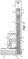
- an SPU 10 of the present invention that may be used in connection with an automated chemical analyzer, such as Access® Special Chemistry Analyzer, described above.
- the SPU 10 includes three (3) main interconnected modules or sections: an onload section 12, a presentation section 14, and an offload section 16.
- the onload section 12 of the SPU 10 has an elongated rail 18 with a distal end 20 and a proximal end 22, an onload motor 24, an onload pusher 26, and an onload sensor 28 located near the proximal end 22 of the rail 18.
- sample racks 4 having an engagement feature 6 and holding multiple (typically 4) sample tubes 2 (as shown in Figure 5) may be placed anywhere on the onload rail 18 as long as there is room available. Priority samples may be placed close to the proximal end 22 of the rail 18. These racks consist of the "onload queue" 30.
- the onload pusher 26 is moved by the onload motor 24 along the rail 18 to push the entire onload queue 30 towards the proximal end 22 of the rail 18 to the presentation section 14 of the SPU 10. During a run, this will also push any racks in a transfer area of the presentation section 14, as well as any racks in an offload staging area of the offload section 16 to an offload queue area of the offload section 16.
- the onload sensor 28 looks for the leading edge of a rack to determine if there are more sample racks to be run. If a rack is detected, it will then look for the trailing edge of the rack. Once the trailing edge is detected, the onload pusher 26 will continue moving another fixed distance to bring this rack to a transfer area of the presentation section 14.
- the presentation section 14 of the SPU 10 has the transfer area 32, an aspiration area 34, a presentation motor 36, a presentation tray 38, a bar code reader (BCR) 40 located near the transfer area 32, and a presentation sensor 42 located at the remote end of the aspiration area 34.
- BCR bar code reader
- the present invention sample presentation unit 10 utilizes an alignment mechanism 60 to provide repeatable rack positions, which in turn provides precise sample tube positioning.
- the alignment mechanism 60 includes an alignment block 62 with precision machined "lead-in" slots 64 which can engage with the engagement feature 6 of the sample racks 4, and spring-biased plungers 66 which force the sample racks 4 against an alignment rail 68.
- the "lead-in" feature 64 of the alignment block 62 forces the sample racks 4 to transport along the rail 68 into their final aspiration positions.
- the precise positioning of all sample tubes 2 in the sample racks 4 are achieved.
- the distance between the lead-in slots 64 on the alignment block 62 is designed slightly wider than the width of each sample rack 4, such that when all sample racks 4 are engaged with the alignment block 62, they are slightly separated to make sure that they do not touch and interfere with each other during aspiration.
- the presentation tray 38 When the cycle begins, the presentation tray 38 is moved by the presentation motor 36 back to its "home" position at the transfer area 32, which also pushes a gate 13 (as shown in Figure 2) of the presentation section 14 out of the way. After the leading racks of the onload queue 30 are pushed into the transfer area 32, the presentation tray 38 is moved forward by the presentation motor 36 to present these sample racks to the aspirate position for sample aliquoting by the main sample aliquoting station of the chemistry analyzer. BCR 40 reads the bar code label of the racks. The sample racks are properly aligned by the alignment mechanism 60, as described in detail above.
- the presentation sensor 42 is provided to detect the status of the presentation motor 36. If the presentation motor 36 functions nonnally, then the presentation sensor 42 will be interrupted within a predetermined range before the presented racks get to the aspirate area 34; otherwise, there is a motion error or motor jam.
- the offload section 16 of the SPU 10 has the offload staging area 44, an offload queue area 46, an offload motor 48, an offload pusher 50, an offload sensor 52 located near the offload queue area 46, and an offload tray 54.
- the present invention SPU 10 may have two (2) distinct offload areas. One of these areas may be simply an extension of the onload and presentation rails. The other area may be perpendicular to the onload and presentation rails. This creates an additional challenge to the stability of the racks. While on the onload rails, the racks are suspended by features well above the center of gravity of the racks, making it impossible for them to fall or tip. When the racks are moved perpendicular to the onload and presentation rail, they are no longer suspended but rather sit on the bottom of the racks. This creates the problem of rack stability as they are being advanced by the offload pusher or during rack removal by the operator. To solve this problem, a series of thin protruding fins are provided extending up from the offload surface.
- These fins are adequately tall and spaced apart such that when a rack is placed between the fins, the rack is stabilized and cannot be tipped. When transitioning into the fins, adequate lead-in is provided on the racks and fins to compensate for slight errors in rack position.
- the offload pusher 50 is moved by the offload motor 48 back to its "home" position at the offload queue area 46.
- the offload sensor 52 is used to determine whether the offload queue area 46 is full. If the offload queue area 46 is full, then the offload motor 48 will move the offload pusher 50 forward to push, for example, four (4) racks in the offload queue area 46 into the offload tray 54. The offload motor 48 will then move the offload pusher 50 back to its home position. However, before the offload pusher 50 gets back to its home position, the offload sensor 52 must be interrupted within a predetermined range; otherwise, it is an indication of a motion error or motor jam.
- the SPU 10 is capable of allowing routine sample racks to be added during a run.
- routine sample racks need to be added during a run, the onload pusher 26 will be moved by the onload motor 24 back to its home position. The operators can then add sample racks anywhere on the onload rail 18 as long as there is room available. "Priority" or “semi-priority” sample racks may be placed in front of the onload queue 30.
- routine loading the operator is locked out of the presentation section by the gate 13 and an enclosed aspiration area 15 (as shown in Figure 2). The instrument can continue all operations with the presentation section during routine loading.
- the SPU 10 is also capable of allowing very high priority sample racks to be added during a run.
- the operator initiates this loading operation by pressing a switch, then the onload pusher 26 is moved by the onload motor 24 back to its home position, and the presentation tray 38 is also moved by the presentation motor 36 back to its loading position. Then the operator can manually push any sample racks in the presentation tray 42 out of the transfer area 32 of the presentation section 14 and any racks on the rail 18 of the onload section 12 all the way towards the distal end 20 of the onload rail 18. The operator can then place STAT sample racks in front of the onload queue. If there is not enough room, the operator can remove some routine sample racks from the onload rail 18 to make room.
- the sample presentation unit of the present invention is provided with the necessary electrical and electronic means for power supply, micro-processor control, and connection with the automated analyzer's main control system for integrated control and operation, all of which are evident to one skilled in the art in view of the instant disclosure.
- the sample presentation unit of the present invention has many unique and advantageous features, including the modular system design that provides a common appearance and functionalities, and is adaptable or easily modifiable to adapt to various immunodiagnostic instruments, and that can be moved away to provide access to other components of the immunodiagnostic instrument while maintaining all alignment information.
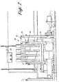
- the SPU 10 may be broken between the two offload areas, as shown in Figure 8.
- the primary portion 70 of the SPU 10 containing the onload section, the presentation section, and the "in-line" offload area can be swung or rotated out away from the analyzer. In order to swing out the primary portion 70, the perpendicular offload area 72 is first transported out of the way.
- the sample presentation unit of the present invention is capable of the quick detection of motion errors or motor jams during operation through the use of strategically located sensors, and is also capable of ascertaining sample identifications ahead of time to allow information to be downloaded from the main host computer that controls the operation of the immunodiagnostic instrument.
- Automated analyzers can request test information from a host computer system to avoid manual station entry if data.
- Host computers may have a time lag of several minutes from being supplied a sample identification to its reply containing test request information. This test request information is necessary to determine what to do with a sample at the time of aspiration.
- the SPU 10 is capable of moving multiple (for example, four) sample racks into the aspiration area 34.
- a subject rack When a subject rack is initially brought into the aspiration area 34, it passes the bar code reader 40 and the query for the required tested information is sent to the host computer. Meanwhile, the aspiration processes for the three racks ahead of the subject rack are running, and by the time the subject rack is up for aspiration, the test request information for the subject tray from the host computer is returned. Using this technique, sample identifications are read well in advance of the actual aspiration. Since during a routine loading operation the aspiration area is protected from operator intervention, the sample order integrity is maintained.
Landscapes
- Chemical & Material Sciences (AREA)
- Chemical Kinetics & Catalysis (AREA)
- Physics & Mathematics (AREA)
- Health & Medical Sciences (AREA)
- Life Sciences & Earth Sciences (AREA)
- Analytical Chemistry (AREA)
- Biochemistry (AREA)
- General Health & Medical Sciences (AREA)
- General Physics & Mathematics (AREA)
- Immunology (AREA)
- Pathology (AREA)
- Automatic Analysis And Handling Materials Therefor (AREA)
Claims (47)
- Vorrichtung zum Präsentieren bzw. Zuführen bzw. Geben von Probengestellen zu einer automatisierten Analysiervorrichtung, umfassend:a. einen Probengestell-Ladeabschnitt, einen Probengestell-Präsentationsabschnitt und einen Probengestell-Entladeabschnitt;b. wobei der Probengestell-Ladeabschnitt einen Ladewarteschlangenbereich und einen Ladebewegungsmechanismus zum Bewegen der Probengestelle, die auf dem Ladewarteschlangenbereich angeordnet sind, zu dem Probengestell-Präsentationsabschnitt aufweist;c. wobei der Probengestell-Präsentationsabschnitt einen Transfer- bzw. Übertragungsbereich, der mit dem Ladewarteschlangenbereich des Probengestell-Ladeabschnitts verbunden ist, um die Probengestelle von dem Probengestell-Ladeabschnitt zu erhalten, einen Probenpräsentationsbereich benachbart der automatisierten Analysiervorrichtung, um Probengestelle für ein An- bzw. Aufsaugen zu präsentieren, und einen Präsentationsbewegungsmechanismus aufweist, der zwischen dem Übertragungsbereich und dem Präsentationsbereich bewegbar ist, um wenigstens eines der Probengestelle von dem Übertragungsbereich zu dem Präsentationsbereich für ein Ansaugen einer Probe zu bewegen und nachfolgend wenigstens eines der Probengestelle von dem Präsentationsbereich zurück zu dem Übertragungsbereich nach einem Ansaugen einer Probe zu bewegen, wobei der Übertragungsbereich eine Mehrzahl der Probengestelle halten kann; undd. wobei der Probengestell-Entladeabschnitt einen Entladebereich, der mit dem Übertragungsbereich des Probengestell-Präsentationsabschnitts verbunden ist, um die Probengestelle von dem Probengestell-Präsentationsabschnitt nach einem Ansaugen einer Probe zu erhalten, und einen Entladebewegungsmechanismus aufweist, um die Probengestelle, die von dem Probengestell-Präsentationsabschnitt erhalten sind, zu einem Probengestellentladetablett bzw. -träger zu bewegen.
- Vorrichtung nach Anspruch 1, wobei der Ladebewegungsmechanismus des Probengestell-Ladeabschnitts einen Ladeschieber umfaßt, der durch einen Lademotor angetrieben ist und fähig ist, entweder ein individuelles oder eine Gruppe von Probengestellen zu schieben.
- Vorrichtung nach Anspruch 1, weiters umfassend einen Ladesensor zur Detektion von Bewegungsfehlern oder Blockaden des Ladebewegungsmechanismus.
- Vorrichtung nach Anspruch 1, wobei der Präsentationsbewegungsmechanismus des Probengestell-Präsentationsabschnitts weiters Mittel zum gleichzeitigen Bewegen einer Mehrzahl von Probengestellen umfaßt.
- Vorrichtung nach Anspruch 4, wobei die gleichzeitigen Bewegungsmittel ein Präsentationstablett bzw. -träger umfassen, das durch einen Präsentationsmotor angetrieben ist und fähig ist, die Mehrzahl von Probengestellen zu halten.
- Vorrichtung nach Anspruch 1, weiters umfassend einen Strichcodeleser zum Erhalten einer Identifikation der Probengestelle, oder von einem oder mehreren Probenbehälter(n), der bzw. die durch die Probengestelle gehalten ist bzw. sind, oder von Probeninhalten, die in den Behältern enthalten sind.
- Vorrichtung nach Anspruch 6, wobei der Strichcodeleser eine Identifikation eines Probengestells oder von einem oder mehreren Probenbehälter(n), der bzw. die durch das entsprechende Probengestell gehalten ist bzw. sind, oder von Probeninhalten, die in Behältern enthalten sind, die durch das entsprechende Probengestell gehalten sind, vor einem Präsentieren des entsprechenden Probengestells zu einem Ansaugort der automatisierten Analysiervorrichtung zum Ansaugen erhält.
- Vorrichtung nach Anspruch 1, weiters umfassend einen Präsentationssensor zur Detektion von Bewegungsfehlern oder Blockaden des Präsentationsbewegungsmechanismus.
- Vorrichtung nach Anspruch 1, weiters umfassend einen Ausrichtmechanismus zum präzisen Positionieren eines Probengestells, das zum Ansaugen präsentiert ist.
- Vorrichtung nach Anspruch 9, wobei der Ausrichtmechanismus Mittel zum präzisen Positionieren des präsentierten Probengestells entlang einer Längsrichtung des präsentierten Probengestells enthält.
- Vorrichtung nach Anspruch 10, wobei die präzisen Positioniermittel in Längsrichtung einen durch eine Feder vorgespannten Kolben umfassen, der mit dem präsentierten Probengestell in Eingriff bringbar ist.
- Vorrichtung nach Anspruch 9, wobei der Ausrichtmechanismus weiters Mittel zum präzisen Positionieren des präsentierten Probengestells entlang einer Querrichtung des präsentierten Probengestells umfaßt.
- Vorrichtung nach Anspruch 12, wobei die präzisen Positioniermittel in Querrichtung einen Einführschlitz umfassen, der mit einem Eingriffsmerkmal des präsentierten Probengestells in Eingriff bringbar ist.
- Vorrichtung nach Anspruch 1, wobei der Entladebewegungsmechanismus des Probengestell-Entladeabschnitts einen Entladeschieber umfaßt, der durch einen Entlademotor angetrieben ist und fähig ist, entweder ein individuelles oder eine Gruppe der Probengestelle zu schieben.
- Vorrichtung nach Anspruch 1, weiters umfassend einen Entladesensor zur Detektion von Bewegungsfehlern oder Blockaden des Entladebewegungsmechanismus.
- Vorrichtung nach Anspruch 1, wobei der Probengestell-Ladeabschnitt, der Probengestell-Präsentationsabschnitt und der Probengestell-Entladeabschnitt als eine Einheit derart verbunden sind, daß sie gemeinsam bewegt werden können, während sie ihre Ausrichtung beibehalten.
- Vorrichtung nach Anspruch 1, weiters umfassend elektronische Mittel, die mit der automatisierten Analysiervorrichtung gekoppelt sind, für eine integrierte Steuerung bzw. Regelung und Betrieb.
- Vorrichtung nach Anspruch 1, wobei der Ladewarteschlangenbereich eine längliche Schiene umfaßt, die ein distales Ende und ein proximales Ende aufweist, wobei der Ladebewegungsmechanismus zum Bewegen der Probengestelle, die auf dem Ladewarteschlangenbereich angeordnet sind, zu dem Probengestell-Präsentationsabschnitt entlang der Schiene bewegbar ist, um die Probengestelle, die auf den Schienen angeordnet sind, zu dem proximalen Ende der Schiene zu bewegen, weiters umfassend:einen Ladesensor, der benachbart dem proximalen Ende der Schiene des Probengestell-Ladeabschnitts angeordnet ist, zur Detektion von Bewegungsfehlern oder Blockaden des Ladebewegungsmechanismus;eine Präsentationssensor, der an dem Präsentationsbereich des Probengestell-Präsentationsabschnitts angeordnet ist, zur Detektion von Bewegungsfehlern oder Blockaden des Präsentationsbewegungsmechanismus; undeinen Entladesensor, der an dem Entladewarteschlangenbereich des Probengestell-Entladeabschnitts angeordnet ist, zur Detektion von Bewegungsfehlern oder Blockaden des Entladebewegungsmechanismus.
- Vorrichtung nach Anspruch 18, wobei der Ladebewegungsmechanismus des Probengestell-Ladeabschnitts einen Ladeschieber umfaßt, der fähig ist, entweder ein individuelles oder eine Gruppe der Probengestelle zu schieben.
- Vorrichtung nach Anspruch 18, wobei der Ladebewegungsmechanismus des Probengestell-Ladeabschnitts weiters einen Lademotor zum Antreiben des Ladeschiebers umfaßt.
- Vorrichtung nach Anspruch 18, wobei der Präsentationsbewegungsmechanismus des Probengestell-Präsentationsabschnitts weiters Mittel zum gleichzeitigen Bewegen einer Mehrzahl der Probengestelle umfaßt.
- Vorrichtung nach Anspruch 21, wobei die Mittel zum gleichzeitigen Bewegen ein Präsentationstablett bzw. -träger umfassen, das durch einen Präsentationsmotor angetrieben ist und fähig ist, die Mehrzahl von Probengestellen zu halten.
- Vorrichtung nach Anspruch 18, weiters umfassend einen Strichcodeleser zum Erhalten der Identifikation der Probengestelle, von einem oder mehreren Probenbehälter(n), der bzw. die durch die Probengestelle gehalten ist bzw. sind, oder von Probeninhalten, die in den Behältern enthalten sind.
- Vorrichtung nach Anspruch 23, wobei der Strichcodeleser die Identifikation eines gegenständlichen Probengestells, oder von einem oder mehreren Probenbehälter(n), der (die) durch das gegenständliche Probengestell gehalten ist bzw. sind, oder von Probeninhalten, die in den Behältern enthalten sind, die durch das gegenständliche Probengestell gehalten sind, vor einem Präsentieren des gegenständlichen Probengestells zu einem Ansaugort der automatisierten Analysiervorrichtung zum Ansaugen erhält.
- Vorrichtung nach Anspruch 18, weiters umfassend einen Ausrichtmechanismus zum präzisen Positionieren eines Probengestells, das zum Ansaugen präsentiert ist.
- Vorrichtung nach Anspruch 25, wobei der Ausrichtmechanismus Mittel zum präzisen Positionieren des präsentierten Probengestells entlang einer Längsrichtung des präsentierten Probengestells umfaßt.
- Vorrichtung nach Anspruch 26, wobei die präzisen Positioniermittel bzw. Mittel zum präzisen Positionieren in Längsrichtung einen durch eine Feder vorgespannten Kolben umfassen, der mit dem präsentierten Probengestell in Eingriff bringbar ist.
- Vorrichtung nach Anspruch 25, wobei der Ausrichtmechanismus weiters Mittel zum präzisen Positionieren des präsentierten Probengestells entlang einer Querrichtung des präsentierten Probengestells umfaßt.
- Vorrichtung nach Anaspruch 28, wobei die präzisen Positioniermittel in Querrichtung einen Einführschlitz umfassen, der mit einem Eingriffsmerkmal des präsentierten Probengestells in Eingriff bringbar ist.
- Vorrichtung nach Anspruch 18, wobei der Entladebewegungsmechanismus des Probengestell-Entladeabschnitts einen Entladeschieber umfaßt, der durch einen Entlademotor angetrieben ist und fähig ist, entweder ein individuelles oder eine Gruppe der Probengestelle zu schieben.
- Vorrichtung nach Anspruch 30, wobei der Entladebewegungsmechanismus des Probengestell-Entladeabschnitts einen Entladeschieber umfaßt, der fähig ist, entweder ein individuelles oder eine Gruppe der Probengestelle zu schieben.
- Vorrichtung nach Anspruch 31, wobei der Entladebewegungsmechanismus des Probengestell-Entladeabschnitts weiters einen Entlademotor zum Antreiben des Entladeschiebers enthält.
- Vorrichtung nach Anspruch 11, wobei der Probengestell-Ladeabschnitt, der Probengestell-Präsentationsabschnitt und der Probengestell-Entladeabschnitt als eine Einheit derart verbunden sind, daß sie gemeinsam bewegt werden können, während sie ihre Ausrichtung beibehalten.
- Vorrichtung nach Anspruch 11, weiters umfassend elektronische Mittel, die mit der automatisierten Analysiervorrichtung gekoppelt sind, für eine integrierte Steuerung bzw. Regelung und Betrieb.
- Vorrichtung nach Anspruch 18, wobei der Ladebewegungsmechanismus einen Ladeschieber umfaßt, der entlang der Schiene bewegbar ist, um die Probengestelle, die auf der Schiene angeordnet sind, zu dem proximalen Ende der Schiene zu bewegen, weiters umfassend:einen Strichcodeleser zum Erhalten der Identifikation der Probengestelle, oder von einem oder mehreren Behälter(n), der bzw. die durch die Probengestelle gehalten ist bzw. sind, oder von Probeninhalten, die in den Behältern enthalten sind.
- Vorrichtung nach Anspruch 35, wobei der Ladebewegungsmechanismus des Probengestell-Ladeabschnitts weiters einen Lademotor zum Antreiben des Ladeschiebers umfaßt.
- Vorrichtung nach Anspruch 35, wobei der Präsentationsbewegungsmechanismus des Probengestell-Präsentationsabschnitts weiters die Mittel zum gleichzeitigen Bewegen einer Mehrzahl der Probengestelle umfaßt.
- Vorrichtung nach Anspruch 37, wobei die gleichzeitigen Bewegungsmittel bzw. Mittel zum gleichzeitigen Bewegen ein Präsentationstablett bzw. -träger umfassen, welches durch einen Präsentationsmotor angetrieben ist und fähig ist, die Mehrzahl von Probengestellen zu halten.
- Vorrichtung nach Anspruch 35, wobei der Strichcodeleser die Identifikation eines gegenständlichen Probengestells, oder von einem oder mehreren Probenbehälter(n), die durch das gegenständliche Probengestell gehalten ist bzw. sind, oder von Probeninhalten, die in den Behältern enthalten sind, die durch das gegenständliche Probengestell gehalten sind, vor einem Präsentieren des gegenständlichen Probengestells zu einem Ansaugort der automatisierten Analysiervorrichtung zum Ansaugen erhält.
- Vorrichtung nach Anspruch 35, weiters umfassend einen Ausrichtmechanismus für das präzise Positionieren eines Probengestells, das für ein Ansaugen präsentiert ist.
- Vorrichtung nach Anspruch 40, wobei der Ausrichtmechanismus die Mittel zum präzisen Positionieren des präsentierten Probengestells entlang einer Längsrichtung des präsentierten Probengestells umfaßt.
- Vorrichtung nach Anspruch 41, wobei die präzisen Positioniermittel in Längsrichtung einen durch eine Feder vorbelasteten Kolben umfassen, der mit dem präsentierten Probengestell in Eingriff bringbar ist.
- Vorrichtung nach Anspruch 40, wobei der Ausrichtmechanismus weiters die Mittel für das präzise Positionieren des präsentierten Probengestells entlang einer querverlaufenden Richtung des präsentierten Probengestells umfaßt.
- Vorrichtung nach Anspruch 43, wobei die präzisen Positioniermittel in Querrichtung einen Einführschlitz umfassen, der mit einem Eingriffsmerkmal des präsentierten Probengestells in Eingriff bringbar ist.
- Vorrichtung nach Anspruch 35, wobei der Entladebewegungsmechanismus des Probengestell-Entladeabschnitts weiters einen Entlademotor zum Antreiben des Entladeschiebers umfaßt.
- Vorrichtung nach Anspruch 35, wobei der Probengestell-Ladeabschnitt, der Probengestell-Präsentationsabschnitt und der Probengestell-Entladeabschnitt als eine Einheit derart verbunden sind, daß sie gemeinsam bewegt werden können, während sie ihre Ausrichtung beibehalten.
- Vorrichtung nach Anspruch 35, weiters umfassend elektronische Mittel, die mit der automatisierten Analysiervorrichtung gekoppelt sind, für eine integrierte Steuerung bzw. Regelung und Betrieb.
Applications Claiming Priority (3)
| Application Number | Priority Date | Filing Date | Title |
|---|---|---|---|
| US848450 | 1992-03-09 | ||
| US09/848,450 US6790413B2 (en) | 2001-05-03 | 2001-05-03 | Sample presentation unit |
| PCT/US2002/007988 WO2002090996A2 (en) | 2001-05-03 | 2002-03-15 | Sample presentation unit |
Publications (2)
| Publication Number | Publication Date |
|---|---|
| EP1410046A2 EP1410046A2 (de) | 2004-04-21 |
| EP1410046B1 true EP1410046B1 (de) | 2005-12-28 |
Family
ID=25303305
Family Applications (1)
| Application Number | Title | Priority Date | Filing Date |
|---|---|---|---|
| EP02723458A Expired - Lifetime EP1410046B1 (de) | 2001-05-03 | 2002-03-15 | Probengebereinheit |
Country Status (4)
| Country | Link |
|---|---|
| US (1) | US6790413B2 (de) |
| EP (1) | EP1410046B1 (de) |
| DE (1) | DE60208381T2 (de) |
| WO (1) | WO2002090996A2 (de) |
Families Citing this family (30)
| Publication number | Priority date | Publication date | Assignee | Title |
|---|---|---|---|---|
| US6825041B2 (en) | 2001-03-16 | 2004-11-30 | Beckman Coulter, Inc. | Method and system for automated immunochemistry analysis |
| US7850914B2 (en) * | 2004-03-05 | 2010-12-14 | Beckman Coulter, Inc. | Specimen-transport module for a multi-instrument clinical workcell |
| WO2005093433A1 (en) * | 2004-03-05 | 2005-10-06 | Beckman Coulter, Inc. | Magnetically attractive specimen-container rack for automated clinical instrument |
| US7842504B2 (en) | 2004-04-02 | 2010-11-30 | Siemens Healthcare Diagnostics Inc. | Method for increasing throughput in an automatic clinical analyzer by duplicating reagent resources |
| USD532524S1 (en) | 2005-05-04 | 2006-11-21 | Abbott Laboratories | Reagent carrier for use in an automated analyzer |
| US7628954B2 (en) * | 2005-05-04 | 2009-12-08 | Abbott Laboratories, Inc. | Reagent and sample handling device for automatic testing system |
| USD534280S1 (en) | 2005-05-04 | 2006-12-26 | Abbott Laboratories | Reagent carrier for use in an automated analyzer |
| USD531736S1 (en) | 2005-05-04 | 2006-11-07 | Abbott Laboratories | Reagent carrier for use in an automated analyzer |
| USD533947S1 (en) | 2005-05-04 | 2006-12-19 | Abbott Laboratories | Reagent carrier for use in an automated analyzer |
| US20070020151A1 (en) | 2005-07-20 | 2007-01-25 | Steven Woodside | Pipette tip holder |
| JP4768409B2 (ja) | 2005-11-15 | 2011-09-07 | シスメックス株式会社 | 試料分析装置、試料分析本体装置、及び試料容器供給装置 |
| CN101479042B (zh) * | 2006-07-04 | 2012-08-08 | 爱朋多夫公司 | 用于实验室液体的模块化存储系统 |
| US7855077B2 (en) * | 2006-09-29 | 2010-12-21 | Beckman Coulter, Inc. | Method and device for test sample loading |
| JP2008209338A (ja) * | 2007-02-28 | 2008-09-11 | Hitachi High-Technologies Corp | 自動分析装置 |
| US8703492B2 (en) | 2007-04-06 | 2014-04-22 | Qiagen Gaithersburg, Inc. | Open platform hybrid manual-automated sample processing system |
| US8357538B2 (en) * | 2007-04-06 | 2013-01-22 | Qiagen Gaithersburg, Inc. | Automated assay and system |
| DE102007044016B4 (de) * | 2007-09-14 | 2010-12-16 | Bruker Biospin Gmbh | Probenwechseleinrichtung mit auf mäanderförmiger Bahn geführten Probenaufnahmen, insbesondere für ein NMR-Spektrometer, und Kernspinresonanz-Spektrometer |
| JP5258615B2 (ja) * | 2009-02-20 | 2013-08-07 | 株式会社東芝 | 自動分析装置 |
| US9953141B2 (en) | 2009-11-18 | 2018-04-24 | Becton, Dickinson And Company | Laboratory central control unit method and system |
| WO2012043261A1 (ja) * | 2010-09-28 | 2012-04-05 | 株式会社日立ハイテクノロジーズ | 検体検査自動化システムおよびその制御方法 |
| CN102313667B (zh) * | 2011-05-27 | 2013-10-02 | 公安部第一研究所 | 一种样品托盘安装装置 |
| CN103048157B (zh) * | 2012-11-30 | 2015-06-24 | 刘小欣 | 病理石蜡标本自动识别机及采用它的检测小车和控制方法 |
| WO2014144870A2 (en) | 2013-03-15 | 2014-09-18 | Abbott Laboratories | Light-blocking system for a diagnostic analyzer |
| US9632103B2 (en) | 2013-03-15 | 2017-04-25 | Abbott Laboraties | Linear track diagnostic analyzer |
| WO2014144825A2 (en) | 2013-03-15 | 2014-09-18 | Abbott Laboratories | Automated reagent manager of a diagnostic analyzer system |
| EP3173793B1 (de) * | 2015-11-30 | 2020-05-13 | F. Hoffmann-La Roche AG | Laborinstrument und verfahren zum betrieb eines laborinstruments |
| CN116825604A (zh) | 2017-05-22 | 2023-09-29 | 拜克门寇尔特公司 | 样品处理系统和由其执行的方法 |
| EP3454064B1 (de) * | 2017-09-08 | 2020-11-11 | F. Hoffmann-La Roche AG | Rack-positionierungssystem |
| CN109580970B (zh) * | 2017-09-29 | 2022-07-15 | 深圳市新产业生物医学工程股份有限公司 | 样本架加载系统、加载方法及化学发光检测仪 |
| EP4411382A3 (de) | 2017-12-19 | 2024-10-23 | Beckman Coulter, Inc. | Integriertes probenverarbeitungssystem mit variablen arbeitsabläufen |
Family Cites Families (38)
| Publication number | Priority date | Publication date | Assignee | Title |
|---|---|---|---|---|
| DE1069904B (de) | 1957-08-05 | 1959-11-26 | ||
| US3724638A (en) | 1971-10-22 | 1973-04-03 | Damon Corp | Sample conveyor and transport system |
| US4582990A (en) | 1980-10-27 | 1986-04-15 | Randam Electronics, Inc. | Analytical instrument with two moving trains of sample holder-carrying trays under microprocessor control |
| DE3246274C2 (de) | 1981-12-14 | 1985-05-30 | Olympus Optical Co., Ltd., Tokio/Tokyo | Mit immunologischer Agglutinationsreaktion arbeitendes Analysiergerät |
| DE3438358A1 (de) | 1984-10-19 | 1986-04-30 | Krones Ag Hermann Kronseder Maschinenfabrik, 8402 Neutraubling | Verfahren und vorrichtung zum melden eines staus auf einem gefaessfoerderer |
| JPS61137066A (ja) | 1984-12-07 | 1986-06-24 | Toshiba Corp | 自動化学分析装置の測光方式 |
| US5306510A (en) | 1988-01-14 | 1994-04-26 | Cyberlab, Inc. | Automated pipetting system |
| US5209903A (en) * | 1989-09-06 | 1993-05-11 | Toa Medical Electronics, Co., Ltd. | Synthetic apparatus for inspection of blood |
| WO1991016675A1 (en) | 1990-04-06 | 1991-10-31 | Applied Biosystems, Inc. | Automated molecular biology laboratory |
| US5207331A (en) | 1991-08-28 | 1993-05-04 | Westinghouse Electric Corp. | Automatic system and method for sorting and stacking reusable cartons |
| JPH05264558A (ja) * | 1992-03-19 | 1993-10-12 | Nittec Co Ltd | 容器の移送装置 |
| US5428470A (en) | 1992-07-17 | 1995-06-27 | Beckman Instruments, Inc. | Modular system and method for an automatic analyzer |
| US5538849A (en) * | 1992-12-29 | 1996-07-23 | Toyo Boseki Kabushiki Kaisha | Apparatus for automated assay of DNA probe and method for assaying nucleic acid in sample |
| US5439645A (en) | 1993-01-25 | 1995-08-08 | Coulter Corporation | Apparatus for automatically, selectively handling multiple, randomly associated hematological samples |
| WO1994018565A1 (en) | 1993-02-01 | 1994-08-18 | Labsystems Oy | Method and means for magnetic particle specific binding assay |
| US5411065A (en) | 1994-01-10 | 1995-05-02 | Kvm Technologies, Inc. | Liquid specimen transfer apparatus and method |
| JPH0835970A (ja) | 1994-07-25 | 1996-02-06 | Hitachi Ltd | 自動分析装置 |
| US5735387A (en) | 1995-07-14 | 1998-04-07 | Chiron Diagnostics Corporation | Specimen rack handling system |
| US5736102A (en) * | 1996-02-21 | 1998-04-07 | Biomerieux Vitek, Inc. | Test sample positioning system |
| JP2988362B2 (ja) * | 1996-03-11 | 1999-12-13 | 株式会社日立製作所 | 多検体分析システム |
| JP3031237B2 (ja) * | 1996-04-10 | 2000-04-10 | 株式会社日立製作所 | 検体ラックの搬送方法及び検体ラックを搬送する自動分析装置 |
| JP3031242B2 (ja) | 1996-05-20 | 2000-04-10 | 株式会社日立製作所 | 多項目分析装置 |
| JP3032159B2 (ja) * | 1996-09-24 | 2000-04-10 | 株式会社日立製作所 | 分析システム |
| US5833925A (en) * | 1996-11-13 | 1998-11-10 | Beckman Instruments, Inc. | Automatic chemistry analyzer with improved ion selective electrode assembly |
| JP3336894B2 (ja) | 1997-01-29 | 2002-10-21 | 株式会社日立製作所 | 自動分析装置 |
| US5861563A (en) | 1997-03-20 | 1999-01-19 | Bayer Corporation | Automatic closed tube sampler |
| JP3428426B2 (ja) * | 1997-03-26 | 2003-07-22 | 株式会社日立製作所 | 検体分析システム |
| DE69835181T2 (de) * | 1997-04-09 | 2006-11-23 | Hitachi, Ltd. | System zur automatischen Probenanalyse und Verfahren zu dessen Betrieb |
| DE69837230T2 (de) * | 1997-04-10 | 2007-12-20 | Hitachi, Ltd. | Automatische Analysevorrichtung |
| DE19819812C2 (de) * | 1998-05-04 | 2000-11-02 | Olympus Diagnostica Gmbh | Laborprimärprobenverteiler mit einer Verteileinrichtung |
| US6331437B1 (en) * | 1998-07-14 | 2001-12-18 | Bayer Corporation | Automatic handler for feeding containers into and out of an analytical instrument |
| JP3930977B2 (ja) * | 1998-07-31 | 2007-06-13 | 株式会社日立製作所 | 検体処理システム |
| CH698240B1 (de) * | 1998-11-17 | 2009-06-30 | Tecan Trading Ag | Verfahren zum Wägen von Proberöhren, Zuführeinrichtung sowie Arbeitsstation. |
| ES2252925T3 (es) * | 1999-05-14 | 2006-05-16 | F. Hoffmann-La Roche Ag | Sistema de analizador automatico. |
| FR2812088B1 (fr) * | 2000-07-21 | 2003-01-24 | Abx Sa | Dispositif de traitement d'echantillons de produits sanguins |
| JP2002048802A (ja) * | 2000-08-07 | 2002-02-15 | Hitachi Ltd | 自動分析システム |
| US20030021728A1 (en) * | 2001-07-26 | 2003-01-30 | Sharpe Richard R. | Method of and apparatus for object-oriented real-time mechanical control of automated chemistry instruments |
| JP5193408B2 (ja) * | 2001-09-13 | 2013-05-08 | ベックマン コールター, インコーポレイテッド | 自動分析装置 |
-
2001
- 2001-05-03 US US09/848,450 patent/US6790413B2/en not_active Expired - Lifetime
-
2002
- 2002-03-15 DE DE60208381T patent/DE60208381T2/de not_active Expired - Lifetime
- 2002-03-15 EP EP02723458A patent/EP1410046B1/de not_active Expired - Lifetime
- 2002-03-15 WO PCT/US2002/007988 patent/WO2002090996A2/en not_active Ceased
Also Published As
| Publication number | Publication date |
|---|---|
| US6790413B2 (en) | 2004-09-14 |
| EP1410046A2 (de) | 2004-04-21 |
| DE60208381T2 (de) | 2006-09-28 |
| DE60208381D1 (de) | 2006-02-02 |
| WO2002090996A3 (en) | 2004-02-19 |
| US20020164269A1 (en) | 2002-11-07 |
| WO2002090996A2 (en) | 2002-11-14 |
Similar Documents
| Publication | Publication Date | Title |
|---|---|---|
| US6790413B2 (en) | Sample presentation unit | |
| US11927598B2 (en) | Automated clinical analyzer system and method | |
| EP2330425B1 (de) | Probenverarbeitungssystem | |
| JP6227811B2 (ja) | 自動分析装置 | |
| US12422449B2 (en) | Sample analysis system and sample analysis method | |
| CA2443392C (en) | Sample handling system | |
| JP2019078769A (ja) | 容器ホルダの保管および供給 | |
| US20050196320A1 (en) | Specimen-transport module for a multi-instrument clinical workcell | |
| US20080041956A1 (en) | Device and method for reading bar codes on an object | |
| CA2946684C (en) | Automated specimen processing systems and methods | |
| WO2005093432A2 (en) | Specimen-transport module for a multi-instrument clinical workcell | |
| US10739363B2 (en) | Method for mixing a liquid in an automated analyzer | |
| CN111051891A (zh) | 连接模块及干涉避免方法 | |
| JP2000314737A (ja) | 検体搬送システム | |
| WO2020085271A1 (ja) | オートサンプラ、自動分析装置、サンプリング方法、及び、自動検査方法 | |
| WO2020085272A1 (ja) | オートサンプラ、自動分析装置、サンプリング方法、及び、自動検査方法 | |
| CN115290911A (zh) | 一种样本架运送和处理装置及分析仪器 | |
| CA3031468C (en) | Automated clinical analyzer system and method | |
| JP4607677B2 (ja) | 自動分析装置の容器搬送機構 |
Legal Events
| Date | Code | Title | Description |
|---|---|---|---|
| PUAI | Public reference made under article 153(3) epc to a published international application that has entered the european phase |
Free format text: ORIGINAL CODE: 0009012 |
|
| 17P | Request for examination filed |
Effective date: 20031203 |
|
| AK | Designated contracting states |
Kind code of ref document: A2 Designated state(s): AT BE CH CY DE DK ES FI FR GB GR IE IT LI LU MC NL PT SE TR |
|
| AX | Request for extension of the european patent |
Extension state: AL LT LV MK RO SI |
|
| GRAP | Despatch of communication of intention to grant a patent |
Free format text: ORIGINAL CODE: EPIDOSNIGR1 |
|
| GRAS | Grant fee paid |
Free format text: ORIGINAL CODE: EPIDOSNIGR3 |
|
| GRAA | (expected) grant |
Free format text: ORIGINAL CODE: 0009210 |
|
| AK | Designated contracting states |
Kind code of ref document: B1 Designated state(s): DE FR GB |
|
| REG | Reference to a national code |
Ref country code: GB Ref legal event code: FG4D |
|
| REF | Corresponds to: |
Ref document number: 60208381 Country of ref document: DE Date of ref document: 20060202 Kind code of ref document: P |
|
| ET | Fr: translation filed | ||
| PLBE | No opposition filed within time limit |
Free format text: ORIGINAL CODE: 0009261 |
|
| STAA | Information on the status of an ep patent application or granted ep patent |
Free format text: STATUS: NO OPPOSITION FILED WITHIN TIME LIMIT |
|
| 26N | No opposition filed |
Effective date: 20060929 |
|
| REG | Reference to a national code |
Ref country code: FR Ref legal event code: PLFP Year of fee payment: 15 |
|
| REG | Reference to a national code |
Ref country code: FR Ref legal event code: PLFP Year of fee payment: 16 |
|
| REG | Reference to a national code |
Ref country code: FR Ref legal event code: PLFP Year of fee payment: 17 |
|
| PGFP | Annual fee paid to national office [announced via postgrant information from national office to epo] |
Ref country code: FR Payment date: 20210210 Year of fee payment: 20 |
|
| PGFP | Annual fee paid to national office [announced via postgrant information from national office to epo] |
Ref country code: GB Payment date: 20210308 Year of fee payment: 20 Ref country code: DE Payment date: 20210302 Year of fee payment: 20 |
|
| REG | Reference to a national code |
Ref country code: DE Ref legal event code: R071 Ref document number: 60208381 Country of ref document: DE |
|
| REG | Reference to a national code |
Ref country code: GB Ref legal event code: PE20 Expiry date: 20220314 |
|
| PG25 | Lapsed in a contracting state [announced via postgrant information from national office to epo] |
Ref country code: GB Free format text: LAPSE BECAUSE OF EXPIRATION OF PROTECTION Effective date: 20220314 |