EP1410534B1 - System and method for mass broadband communications - Google Patents
System and method for mass broadband communications Download PDFInfo
- Publication number
- EP1410534B1 EP1410534B1 EP02743402A EP02743402A EP1410534B1 EP 1410534 B1 EP1410534 B1 EP 1410534B1 EP 02743402 A EP02743402 A EP 02743402A EP 02743402 A EP02743402 A EP 02743402A EP 1410534 B1 EP1410534 B1 EP 1410534B1
- Authority
- EP
- European Patent Office
- Prior art keywords
- patch
- interface
- network
- signals
- subscriber
- Prior art date
- Legal status (The legal status is an assumption and is not a legal conclusion. Google has not performed a legal analysis and makes no representation as to the accuracy of the status listed.)
- Expired - Lifetime
Links
Images


Classifications
-
- H—ELECTRICITY
- H04—ELECTRIC COMMUNICATION TECHNIQUE
- H04B—TRANSMISSION
- H04B10/00—Transmission systems employing electromagnetic waves other than radio-waves, e.g. infrared, visible or ultraviolet light, or employing corpuscular radiation, e.g. quantum communication
- H04B10/11—Arrangements specific to free-space transmission, i.e. transmission through air or vacuum
- H04B10/112—Line-of-sight transmission over an extended range
- H04B10/1123—Bidirectional transmission
- H04B10/1125—Bidirectional transmission using a single common optical path
Definitions
- the present invention relates to a system and method for high-density subscriber communications.
- Wired systems rely on conducting cables being deployed (either underground or overground) to each subscriber's premises.
- the cables may conduct either electrical or optical signals.
- the cost of this is very high for high bandwidth systems.
- wireless - makes use of free-space electromagnetic radiation to carry signals between subscribers.
- Wireless systems themselves break down into radio frequency systems - those that use electromagnetic waves of frequency less than ⁇ 10 12 Hz ⁇ - and which have been well-known for almost a century and optical systems which arguably have an even longer pedigree. More recently, however, systems that use infrared radiation (between 800 nm to 50,000 nm in wavelength) have become popular because of improvements in the generation and detection technologies of radiation of these wavelengths. In principle, even shorter wavelength radiation and beyond could be used: the practical difficulties with the detection and emission technologies prevent this at present.
- Frequency, time and code systems operate by encoding the signals to be transmitted in differing ways to pack these resources with as many signals as possible without adverse interference taking place.
- Each of these systems increases the complexity and hence cost of the necessary equipment, but with the pay back of allowing higher subscriber densities to be reached.
- time-division multiplexing is probably the most straightforward and easiest to implement in a practical system (especially optical systems).
- Space division multiplexing essentially makes use of the geometrical properties of the transmitted radiation, such as collimation angle and effective range, to mitigate interference by restricting the spatial spread of radiation. This means that sets of devices, either out of range of each other, or within specific angular ranges of each other can re-use a given frequency without interference in principle. These two types of space-division multiplexing are demonstrated by a modem multi-sectored GSM base-station cell.
- transmitters and receivers need to be carefully designed to take full advantage of the range and angular degrees of freedom. Indeed, some RF, and most optical, systems make use of highly collimated radiation beams so that the angular spread of these beams is very low; and hence the spectrum re-use can be very high.
- a key problem with these so called “point to point” and “mesh” systems is that sophisticated means of aligning and re-aligning the transmitters and receivers of the beams become necessary - again increasing unit cost and installation complexity and time. This is because subscribers' geographic locations do not lie in regular geometric patterns and the equipment deployed at these locations has to be able to cope with this.
- broadband access wireless communications systems are generally intended to be deployed in highly populated areas, which means that buildings obscure lines of sight. The design and deployment of these systems therefore involves much time and effort in arranging for line of sight, or near line of sight positioning of the subscriber and system equipment, since subscriber units must be placed in prominent positions, above roof lines, on the sides of tall buildings etc. In turn, this increases installation problems and the complexity of the systems and, in some territories, causes problems related to planning consent - where regulations do not permit the mounting or display of objects above certain dimensions, or not conforming to certain aesthetics.
- cover a term originating in cellular, or point-to-multipoint, radio systems in which the subscriber units (fixed or mobile) are divided into geographic areas (or “cells") each serviced by a multi-channel transceiver "base-station".
- base-stations have to be deployed such that there is a high probability that any subscriber within range can communicate with the base-station. If this is so, the subscriber unit is described as “covered” by the base-station.
- the term “covered” or “coverage” is used to mean the possibility of a subscriber communicating with the rest of the system - this does not necessarily imply a cellular or point-to-multipoint system.
- WO 99/67903 disdoses a communication network comprising several areas, wherein each area comprises a so-called curb and there is a local network per curb. Subscribers in these local networks communicate with the curb by means of wireless optical signals.
- US-5566022 relates to an indoor wireless communication system comprising omnidirectional transmitters and receivers and a plurality of relays for transmitting and receiving infrared signals through free air.
- EP-1085707 describes a communications system which has a plurality of nodes, each node having a wireless transmitter and receiver for wireless transmission and reception of signals. Each node also has means for determining if a signal received by said node includes information for another node and for causing a signal including said information to be transmitted by said transmitting means to another node if said signal includes information for another node. Each node has a substantially uni-directional point-to-point wireless link to one other node only.
- this patent discloses a network system that is built from many collimated radio links between pairs of radio transceiver devices ("nodes") located on subscriber premises. In any configuration of the network, each radio link is specific to one particular transmitter node and one particular receiver node.
- Each node mayhave more than one such link to a set of other nodes.
- the network system disclosed is a multi-hop or "mesh" architecture, in which each node may carry traffic for other nodes as well as sourcing and sinking traffic itself. The nodes do this by examining the signals sent on each link to find routing information embedded in the signals, and then acting on this information.
- the spectral efficiency of this invention is good, but limited by the fact that its space-division multiplexing is based on angular (azimuthal) sectors. This means that spectral efficiency is obtained by the use of high-gain antennas. To increase spectral efficiency means increasing antenna gain and hence aperture. Spectral efficiency in this system is therefore bought at the expense of large nodes that increases their installation difficulty. In addition, this system requires a complex decoding process of the received signals, in each node, to establish the routing of information across the network. This again adds to node cost and complexity, and hence network economics and ease of installation.
- WO99/4566 describes a free-space laser communications system that is comprised of a large number of picocells.
- Each picocell comprises a single base-station providing conventional (RF) communication with one or more (usually many) users.
- Each base-station also comprises at least two laser transceivers that are mechanically pointed in space by means of an automatic alignment mechanism.
- These optical transceivers allow a point-to-point mesh of base-stations to be constructed that forms an intermediate back-haul network for the end-user traffic.
- access to the end user is effected by prior art means: an RF cellular transceiver system.
- the novel backhaul mechanism makes use of highly collimated optical beams as fixed communication links.
- the absolute need to align accurately the backhaul links increases the complexity and size of the base-station equipment. Because the picocell range is of the order of 100m, this means that in order to service 1 square kilometre, approximately 30-35 such base-stations would required (assuming a uniform deployment density). The economics of such numbers of complex installations would tend to mitigate against mass market rollout.
- Nokia discloses a system of roof-top mounted wireless routers, which is claimed to allow various types of telecommunications operator to deliver broadband access to a larger customer base than could be reached using purely wired means.
- IP packet-based
- mesh packet-based multihop
- These routers operate in license-exempt RF bands (e.g. 2.4 GHz, and 5.8 GHz) that have limited spectrum available for user traffic.
- Information traverses several hops (typically 3-4) before reaching another type of unit (“airhead”) which acts as a data concentrating interface to a wired conventional network point of presence (POP).
- POP network point of presence
- the limited available spectrum together with the unrestricted broadcast nature of the system wireless links imply that the deployment density of the equipment is restricted. This is mitigated to some extent by the system's intrinsic support for packet-based (IP) communications protocols that are not time sensitive. However, the provision of strictly time sensitive services, such E1/T1, would severely limit the capacity of this system.
- US-5724168 discloses a wireless diffuse infrared local area network communication system which operates in enclosed (indoor) areas.
- the communication system includes a controller and a central substantially omni-directional infrared transceiver disposed on the inside walls of the enclosed area operatively connected with the controller.
- the system further includes a remote station and means, operatively coupled to the remote station, for transceiving a communicated signal with the omni-directional infrared transceiver.
- the remote units communicate only with the central transceiver either by a single-frequency direct line of sight or by means of reflections from the walls of the enclosure. Hence the units are immersed in a substantially isotropic radiation bath.
- the role of enclosure walls in this invention appears to be to provide reflecting surfaces so that the remote (mobile) units need not be pointed towards the central transceiver.
- TDMA time-division multiple access
- the present invention relates to a mass communications network system -according to claim 1- and a method for providing broadband mass communications-according to claim 12- and is based on modified free-space optical transmission of signals.
- the system comprises at least one, and preferably many, "patches”.
- Each patch comprises a geographical grouping of network subscribers, each having a subscriber unit (SU) installed on their premises or nearby, and various objects in the environment, such as buildings, in the vicinity.
- SU subscriber unit
- a significant aspect of the invention is the use of objects in the environment, such as buildings, in and around the patch to modify the way signals are propagated within the patch between SUs.
- Physical objects disposed in space have certain properties with respect to the propagation of electromagnetic radiation in the intervening spaces.
- this invention advantageously relates to:
- a realisable and equipped FPZ is referred to as a "Patch".
- a broad band mass communications network system comprising:
- the invention thus exploits the shadowing properties of objects in the environment to divide space up into regions, called "patches", in which a wireless frequency channel can be re-used without interfering with the same channel in neighbouring patches.
- This has the advantage of achieving high spectral efficiency through space division multiplexing.
- the SUs are connected to their subscriber's customer premises equipment and can pass information between each other by means of signals impressed on a carrier operating in the infrared (IR) region of the electromagnetic spectrum.
- IR infrared
- the SUs are substantially omni-directional, and all the SUs in a particular patch are in direct line of sight of each other. This allows the maximum bandwidth to be packed into the available frequencies in a patch, and means that the SUs need not be aligned with precision. By the same token, SUs in different patches are not within line of sight to each other and cannot directly communicate.
- the maximum linear dimension of a patch may be of the order of 200m.
- This invisibility of SUs in different patches is due principally to physical obstructions in the natural and built environment in which the SUs are installed.
- physical obstructions are building walls, fences, trees, geographic features etc.
- the invention can achieve very high spectral re-use (and hence high subscriber densities). This high re-use is not due principally to the equipment design - but rather the way in which the equipment is deployed as a system. Exploiting these shadowing effects also means that SUs need not be roof or chimney mounted, but can be mounted at much lower levels.
- the SUs' signals are preferably emitted and received in a substantially omni-directional fashion. This feature significantly reduces the cost and complexity of the equipment, and greatly facilitates physical installation owing to the resulting equipment size and weight reduction.
- Patches may transport not only signals originating and terminating internally to the patch, but also signals received from or to be transported to other patches.
- a method for providing broad band mass communications comprising:
- the method of communication in and between patches in the present invention is designed to emulate closely that of a piece of electrical cable. Hence, the invention is transparent to end-user protocols.
- a principle component of the present invention is the patch 10, one embodiment of which is illustrated in Figure 2.
- a network system according to the invention comprises one or more such patches 10.
- Each patch 10 comprises two or more subscriber units (SU) 12 and various physical obstructions 14 forming a conceptual boundary of the patch 10.
- the SUs 12 of a patch 10 are mounted for example on respective buildings 16 such that they are each in line of sight of each other and such that optically opaque parts of the patch boundary 14 shield them from SUs 12 in other patches 10.
- each SU 12 consists of two basic parts: an outdoor-mounted communication "head" unit 18, and an indoor interface unit 20 for user access to the network system.
- the two parts 18, 20 are connected by means of a suitable short-run cable assembly 22. This is illustrated in the diagram in the figure 1a.
- FIG. 1b shows a prior art wireless unit - approximately to scale. It can be seen that the prior art unit is significantly larger (due to the physics of the antennas) than the SU 12 of the present invention. Further, unlike the prior art unit, the SU 12 of the present invention is not required to be mounted above the roof ridge - but much lower down.
- the diagram in figure 2 illustrates how a typical patch may be realised in practice.
- Each SU 12 includes a transmitter sub-system and a receiver sub-system as described below, and is arranged to emit and receive IR radiation in a substantially omni-directional fashion in azimuth. In elevation, the pattern can be more collimated.
- the SUs 12 are also adapted to have the ability to modify this radiation pattern to take account of non-ideal patch boundaries 14.
- a patch boundary 14 can be thought of as an irregular polygon of 1 or more sides that are made up of the following elements
- Patch formation is simplest where the candidate patch boundary, whatever its exact shape, has entirely opaque elements. However, non-ideal boundaries 28 will be encountered in practice. To be able to cope with as many different types of patch boundary as possible, the SUs are designed to have the following features:-
- Figure 3b illustrates the use of these features with specific non-ideal patch boundaries. These sorts of boundaries are likely to be encountered in high-density, low-rise, housing estates arranged along linear service roads.
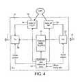
- the subscriber OUT buffer 36 is connected to the IR transmitter subsystem TX 30 as is the transmit buffer TX_FIFO 40.
- the IR receiver subsystem RX 32 is connected to an input 42 of the transmit buffer TX_FIFO 40 and to the subscriber IN buffer 38.
- IR signals (represented by arrow R) detected by the receiver subsystem RX 32 are converted to digital electronic form and are presented either to the subscriber IN buffer 38 (for data being consumed at this SU - the SINK path) or to the transmit buffer TX_FIFO 40 for onward processing for another SU 12 (the TRANSIT path).
- the transmitter buffer TX_FIFO 40 is emptied by the transmitter subsystem TX 30 taking digital data and converting it into suitable signals for IR transmission (represented by arrow T). Digital electronic data from the subscriber OUT buffer 36 is also presented to the transmitter subsystem TX 30 for similar conversion and emission (the SOURCE path).
- each SU has a controller 44 including a stored program of instructions arranged to be executed at regular clock intervals ("timeslots") which are common to all the other components of the network system.
- timeslots regular clock intervals
- synchronisation of individual clocks in different SUs 12 can be accomplished by providing each SU 12 with access to the signals of a primary reference clock, for example, as is available with the GPS system.
- the stored program of each SU can be downloaded over the air from a central network management facility.
- interconnections actually in use are shown as lines between the units. It is important to note that these interconnections may be changed very quickly - either to add/remove subscribers from a patch 10 or in response to a change of traffic loading in the patch 10 - without the need for anything (field units, installers etc.) to move physically.
- FIG. 11 A modification of the SU12 of Figure 4 is shown in Figure 11. Like parts are designated by same reference numerals.
- TX2 IR transmitter sub-system
- RX2 additional IR receiver sub-system
- TX2 subscriber "out” and "in” buffers 36, 38 and to the transmit buffer TX_FIFO 40 and the controller 44 in the same way as the transmitter and receiver sub-systems 30, 32.
- Respective angular segments of signal transmission or reception associated with the SU112 are then allocated their own transmitter and receiver sub-system 30, 32 or 130, 132, and the controller 44 is arranged to select the appropriate pair for transmission/reception in a particular angular segment. In this way, suppression of carrier signals from the SU may be achieved over selected angular ranges.
- communications paths can thus be set up between multiple, arbitrary, pairs of users to allow them to inter-communicate substantially simultaneously.
- signals can be passed between patches 10 as is shown in figure 5.
- a patch 10 also contains one or more SUs 12 that are connected to a second type of unit called a Patch Interface Point (PIP) 46.
- PIP Patch Interface Point
- a patch 10 also contains one or more SUs 12 that are connected to a second type of unit called a Patch Interface Point (PIP) 46.
- PIP Patch Interface Point
- this connection is achieved by means of short-run cables.
- the PIP 46 appears to an SU 12 as its indoor interface.
- An SU so connected will be referred to as a "portal" unit 48 in the following. Normally one portal 48 is connected to one PIP 46, and one PIP 46 is connected to two or more portals 48 in different patches 10.
- a PIP 46 can be either an indoor or outdoor mounted unit. Thus PIPs 46 are located where two or more patches are spatially substantially adjacent, for example on opposite sides of a building. A collection of interconnected patches is illustrated in figure 6a below. In this figure, only the PIPs 46 and the patch boundaries 14 have been shown for clarity.
- an SU12 in a patch 10 fails, for whatever reason, service need only be interrupted for an appreciable amount of time for the subscriber immediately attached the faulty unit.
- the patch connections may be redefined remotely so that other subscribers' service is unaffected. If necessary, a service call can be made on the particular subscriber affected to replace the SU12; no other field action is required. This is a very important factor.
- a PIP 46 can be thought of as a programmable switch, consisting of the components illustrated in figure 7 and having two sub-systems as follows:
- a controller 54 including a reference clock is also provided for controlling the operation of the PIP 46 such that, on each timeslot (see above), the PIP 46 does the following:-
- the PIPs 46 may also be interconnected by point-to-point wireless links, such as supported by existing IR or RF link products.
- point-to-point wireless links such as supported by existing IR or RF link products.
- this has the potential disadvantage of providing additional equipment for installation, maintenance and management, and may cause interference problems within patches.
- the PMP, or pico-cell, topology is, in fact, an instance of one of many topologies that are possible to implement using the programmable nature of patch components - see below.
- This invention therefore encompasses prior-art system topologies, but in a more general and practical way for broadband, high subscriber density systems.
- a core network interface (CNI) 56 is used as shown in Figure 6b. This ensures that signals can pass from a segment 58 of a network according to the present invention to a trunk 60 of the core network and vice versa.
- This type of connection requires more functionality than is required for a PIP 46, and is needed in far fewer locations in a network according to the present invention than are PIPs 46. Hence, economics dictate the need for an additional, specialised unit to carry out this role.
- a CNI 56 is solely concerned with data interfacing and not with service coverage of subscribers. Therefore, a CNI 56 can be located anywhere in the network but preferably near to a suitable core-network point of presence.
- the data from all the connected subscribers arrives at a CNI 56 in a time-scrambled fashion in that consecutive timeslots are likely to contain data from different users. Therefore, a key job of the CNI 56 is to process such aggregated subscriber data streams and present these, suitably disentangled, to the core network.
- the CNI 56 can be designed so that this de-scrambling can be separated from the standard data aggregation and interfacing functions to the core network. In this way, a network according to the present invention can be independent of the actual transport protocols in use by the network operator and subscribers.
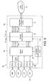
- the CNI 56 is analogous to the PIP 46 in its internal functionality, as illustrated in figure 8. However, the CNI 56 has an additional function for interfacing to a standard core network. Referring to figure 8, the CNI can be thought of as consisting of two halves, 62, 64, labelled the "P side” and the "S side” in the figure. On the P-side, data is handled according to the principles and operation of the present invention. On the "S-side" data is handled according to some standard transport protocol, for example, ATM, IP, etc.
- the main sub-systems of the CNI 56 are:-
- a controller 76 including a reference clock 78 controls the operation of the CNI 56 such that it performs the following functions in each system timeslot:-
- the present invention employs a time-division multiple access (TDMA) regime, which is a standard technique - related to the synchronisation outlined above.
- TDMA time-division multiple access
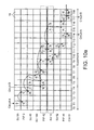
- FIG. 10a time, quantised in terms of the system timeslots, TO, TI, T2 etc, is drawn along the x-axis.
- the y-axis is divided up amongst the SUs 12, PIPs 46, and CNI(s) 56.
- Each cell 76 in this table can be used to represent what each such unit is doing in its particular time-slot.
- the time axis is cyclical in that, after a certain number of time slots all activities are repeated. We refer to this repeat period as a "superframe" in the following description
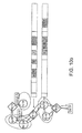
- the diagram in figure 10a also shows two "circuits", designated “circuit A” and “circuit B", in a fragment of a network shown in figure 10b.
- Each such circuit is supported by the coordinated actions of the associated SUs 12 and PIPs 46 as described above.
- the user of circuit B has requested, and been given, twice the bandwidth of the user of circuit A. Circuit B thus uses two timeslots whereas circuit A uses only one timeslot.
- Network management software is responsible for determining and configuring the action of the appropriate device (i.e. SU 12, PIP routing table, CNI routing table) in each timeslot of the superframe (or each cell of the above table) to achieve the required data connections.
- the management software carries out this task in parallel with the network operation, whilst users are making requests for service.
- the table of figure 10a when configured by the network management software, can be viewed as a set of horizontal strips - one for each unit 12, 46 etc - each strip then represents a cyclical list of detailed operating instructions (or "operating program") for each unit. This is illustrated in figure 10b for a respective PIP 46 and SU 12. It is these and related lists that are loaded to the network unit by the management system to allow the network to operate.
- the network components of the present invention are configured and otherwise managed remotely by server software of a network management system 78, for example, based at the network operator's network control centre 80, or IT control room (in the case of private networks). This is illustrated in figure 9.
- the SU, PIP and CNI units operate in an autonomous, though co-operative, fashion as described above to transport data through the network.
- the services of the network management system are required if the network elements need to be configured or re-configured.
- the network management system 78 makes use of a separate network control and management centre 81 to send and receive commands and data to/from the network elements (SU 12, PIP 46 etc) via one or more proxy "element manager" 82 located at convenient points in the network (for example at a CNI site), as is well known from public telecommunications networks.
- a separate network control and management centre 81 to send and receive commands and data to/from the network elements (SU 12, PIP 46 etc) via one or more proxy "element manager" 82 located at convenient points in the network (for example at a CNI site), as is well known from public telecommunications networks.
- the management network used by the network management and control centre 81 can be implemented on top of the network services provided by the present invention - a so-called "in-band" management network - again, as is common to public telecommunications networks.
- the present invention needs to be internally synchronised as stated above. However, this synchronisation does not necessarily need to be the same as, or related to any synchronisation in the user-level, e.g. EI/TI, services carried by the present invention.
- the architecture of the present invention allows a great deal of flexibility (unlike PMP and wired systems) over the timing and ordering of these activities, and exactly which is used will depend on a particular operator's strategy and finance management.
- the provision of services within a new region may comprise the following steps:-
- the present invention can support whichever method is used in practice.
- the SUs 12 and PIPs 46 require straightforward mounting - at eaves' height at maximum. In the first instance, this installation is envisaged to be done by the operator (or contractors) rather than the subscribers themselves.
- This step checks that this connection is useable before the subscriber sends data, by carrying out certain end-to-end tests and performance checks. If the tests are passed, the subscriber is free to send data. If not, then further diagnostic work will need to be done by the operator.
- the present invention as described above has a number of significant advantages, some at least of which are set out below.
- the system exploits key features of urban and semi-urban geography which are problematic to conventional systems.
- Network/System Management techniques/procedures can be inherently automated and simple. There is no need to orientate an SU either on installation or subsequently.
Landscapes
- Physics & Mathematics (AREA)
- Electromagnetism (AREA)
- Engineering & Computer Science (AREA)
- Computer Networks & Wireless Communication (AREA)
- Signal Processing (AREA)
- Mobile Radio Communication Systems (AREA)
- Data Exchanges In Wide-Area Networks (AREA)
- Radio Relay Systems (AREA)
- Small-Scale Networks (AREA)
- Radar Systems Or Details Thereof (AREA)
Applications Claiming Priority (3)
| Application Number | Priority Date | Filing Date | Title |
|---|---|---|---|
| GBGB0117177.6A GB0117177D0 (en) | 2001-07-13 | 2001-07-13 | System and method for mass broadband communications |
| GB0117177 | 2001-07-13 | ||
| PCT/GB2002/003032 WO2003007510A2 (en) | 2001-07-13 | 2002-06-28 | System and method for mass broadband communications |
Publications (2)
| Publication Number | Publication Date |
|---|---|
| EP1410534A2 EP1410534A2 (en) | 2004-04-21 |
| EP1410534B1 true EP1410534B1 (en) | 2006-05-31 |
Family
ID=9918485
Family Applications (1)
| Application Number | Title | Priority Date | Filing Date |
|---|---|---|---|
| EP02743402A Expired - Lifetime EP1410534B1 (en) | 2001-07-13 | 2002-06-28 | System and method for mass broadband communications |
Country Status (16)
| Country | Link |
|---|---|
| US (1) | US20040213294A1 (cs) |
| EP (1) | EP1410534B1 (cs) |
| CN (1) | CN1554161A (cs) |
| AT (1) | ATE328409T1 (cs) |
| BG (1) | BG108579A (cs) |
| CA (1) | CA2457702A1 (cs) |
| CZ (1) | CZ2004228A3 (cs) |
| DE (1) | DE60211908T2 (cs) |
| ES (1) | ES2261689T3 (cs) |
| GB (2) | GB0117177D0 (cs) |
| HU (1) | HUP0401259A2 (cs) |
| NZ (1) | NZ531056A (cs) |
| RU (1) | RU2305373C2 (cs) |
| SK (1) | SK972004A3 (cs) |
| WO (1) | WO2003007510A2 (cs) |
| ZA (1) | ZA200401113B (cs) |
Families Citing this family (176)
| Publication number | Priority date | Publication date | Assignee | Title |
|---|---|---|---|---|
| US8605579B2 (en) * | 2005-10-17 | 2013-12-10 | Qualcomm Incorporated | Method and apparatus for flow control of data in a mesh network |
| US20070248116A1 (en) | 2006-04-21 | 2007-10-25 | Masashi Hamada | Communication control apparatus and method of controlling same |
| FR2907627B1 (fr) * | 2006-10-20 | 2008-12-19 | Alcatel Sa | Dispositif de selection de type de canal de transport pour la diffusion de contenus vers des terminaux de communication |
| US8811903B2 (en) | 2009-05-28 | 2014-08-19 | Microsoft Corporation | Spectrum assignment for networks over white spaces and other portions of the spectrum |
| CN101986578A (zh) * | 2009-07-29 | 2011-03-16 | 中国科学院空间科学与应用研究中心 | 一种自由大气的紫外光通信系统 |
| RU2424572C1 (ru) * | 2009-11-12 | 2011-07-20 | Федеральное государственное унитарное предприятие "Центральный научно-исследовательский институт машиностроения" (ФГУП ЦНИИмаш) | Способ повышения надежности изделий (варианты) |
| US8473989B2 (en) * | 2010-06-24 | 2013-06-25 | Microsoft Corporation | Enabling white space networks independent of low-threshold sensing |
| RU2454707C1 (ru) * | 2011-02-15 | 2012-06-27 | Учреждение Российской академии наук Институт проблем управления им. В.А. Трапезникова РАН | Устройство синхронизации источников оптических сигналов |
| US8750783B2 (en) * | 2011-09-16 | 2014-06-10 | Broadcom Corporation | Efficient enablement for wireless communication on license-exempt bands |
| JP6003514B2 (ja) * | 2012-03-01 | 2016-10-05 | ソニー株式会社 | 情報処理装置、通信システムおよびチャンネル設定方法 |
| EP2863671B1 (en) * | 2012-07-02 | 2016-09-07 | Huawei Technologies Co., Ltd. | Spectrum bandwidth allocation method and device |
| US9113347B2 (en) | 2012-12-05 | 2015-08-18 | At&T Intellectual Property I, Lp | Backhaul link for distributed antenna system |
| US10009065B2 (en) | 2012-12-05 | 2018-06-26 | At&T Intellectual Property I, L.P. | Backhaul link for distributed antenna system |
| US9999038B2 (en) | 2013-05-31 | 2018-06-12 | At&T Intellectual Property I, L.P. | Remote distributed antenna system |
| US9525524B2 (en) | 2013-05-31 | 2016-12-20 | At&T Intellectual Property I, L.P. | Remote distributed antenna system |
| US8897697B1 (en) | 2013-11-06 | 2014-11-25 | At&T Intellectual Property I, Lp | Millimeter-wave surface-wave communications |
| US9209902B2 (en) | 2013-12-10 | 2015-12-08 | At&T Intellectual Property I, L.P. | Quasi-optical coupler |
| US9692101B2 (en) | 2014-08-26 | 2017-06-27 | At&T Intellectual Property I, L.P. | Guided wave couplers for coupling electromagnetic waves between a waveguide surface and a surface of a wire |
| US9768833B2 (en) | 2014-09-15 | 2017-09-19 | At&T Intellectual Property I, L.P. | Method and apparatus for sensing a condition in a transmission medium of electromagnetic waves |
| US10063280B2 (en) | 2014-09-17 | 2018-08-28 | At&T Intellectual Property I, L.P. | Monitoring and mitigating conditions in a communication network |
| US9628854B2 (en) | 2014-09-29 | 2017-04-18 | At&T Intellectual Property I, L.P. | Method and apparatus for distributing content in a communication network |
| US9615269B2 (en) | 2014-10-02 | 2017-04-04 | At&T Intellectual Property I, L.P. | Method and apparatus that provides fault tolerance in a communication network |
| US9685992B2 (en) | 2014-10-03 | 2017-06-20 | At&T Intellectual Property I, L.P. | Circuit panel network and methods thereof |
| US9503189B2 (en) | 2014-10-10 | 2016-11-22 | At&T Intellectual Property I, L.P. | Method and apparatus for arranging communication sessions in a communication system |
| US9762289B2 (en) | 2014-10-14 | 2017-09-12 | At&T Intellectual Property I, L.P. | Method and apparatus for transmitting or receiving signals in a transportation system |
| US9973299B2 (en) | 2014-10-14 | 2018-05-15 | At&T Intellectual Property I, L.P. | Method and apparatus for adjusting a mode of communication in a communication network |
| US9520945B2 (en) | 2014-10-21 | 2016-12-13 | At&T Intellectual Property I, L.P. | Apparatus for providing communication services and methods thereof |
| US9653770B2 (en) | 2014-10-21 | 2017-05-16 | At&T Intellectual Property I, L.P. | Guided wave coupler, coupling module and methods for use therewith |
| US9780834B2 (en) | 2014-10-21 | 2017-10-03 | At&T Intellectual Property I, L.P. | Method and apparatus for transmitting electromagnetic waves |
| US9627768B2 (en) | 2014-10-21 | 2017-04-18 | At&T Intellectual Property I, L.P. | Guided-wave transmission device with non-fundamental mode propagation and methods for use therewith |
| US9769020B2 (en) | 2014-10-21 | 2017-09-19 | At&T Intellectual Property I, L.P. | Method and apparatus for responding to events affecting communications in a communication network |
| US9312919B1 (en) | 2014-10-21 | 2016-04-12 | At&T Intellectual Property I, Lp | Transmission device with impairment compensation and methods for use therewith |
| US9564947B2 (en) | 2014-10-21 | 2017-02-07 | At&T Intellectual Property I, L.P. | Guided-wave transmission device with diversity and methods for use therewith |
| US9577306B2 (en) | 2014-10-21 | 2017-02-21 | At&T Intellectual Property I, L.P. | Guided-wave transmission device and methods for use therewith |
| US10243784B2 (en) | 2014-11-20 | 2019-03-26 | At&T Intellectual Property I, L.P. | System for generating topology information and methods thereof |
| US10009067B2 (en) | 2014-12-04 | 2018-06-26 | At&T Intellectual Property I, L.P. | Method and apparatus for configuring a communication interface |
| US9800327B2 (en) | 2014-11-20 | 2017-10-24 | At&T Intellectual Property I, L.P. | Apparatus for controlling operations of a communication device and methods thereof |
| US9544006B2 (en) | 2014-11-20 | 2017-01-10 | At&T Intellectual Property I, L.P. | Transmission device with mode division multiplexing and methods for use therewith |
| US9461706B1 (en) | 2015-07-31 | 2016-10-04 | At&T Intellectual Property I, Lp | Method and apparatus for exchanging communication signals |
| US10340573B2 (en) | 2016-10-26 | 2019-07-02 | At&T Intellectual Property I, L.P. | Launcher with cylindrical coupling device and methods for use therewith |
| US9997819B2 (en) | 2015-06-09 | 2018-06-12 | At&T Intellectual Property I, L.P. | Transmission medium and method for facilitating propagation of electromagnetic waves via a core |
| US9742462B2 (en) | 2014-12-04 | 2017-08-22 | At&T Intellectual Property I, L.P. | Transmission medium and communication interfaces and methods for use therewith |
| US9954287B2 (en) | 2014-11-20 | 2018-04-24 | At&T Intellectual Property I, L.P. | Apparatus for converting wireless signals and electromagnetic waves and methods thereof |
| US9654173B2 (en) | 2014-11-20 | 2017-05-16 | At&T Intellectual Property I, L.P. | Apparatus for powering a communication device and methods thereof |
| US9680670B2 (en) | 2014-11-20 | 2017-06-13 | At&T Intellectual Property I, L.P. | Transmission device with channel equalization and control and methods for use therewith |
| US10144036B2 (en) | 2015-01-30 | 2018-12-04 | At&T Intellectual Property I, L.P. | Method and apparatus for mitigating interference affecting a propagation of electromagnetic waves guided by a transmission medium |
| US9876570B2 (en) | 2015-02-20 | 2018-01-23 | At&T Intellectual Property I, Lp | Guided-wave transmission device with non-fundamental mode propagation and methods for use therewith |
| US9749013B2 (en) | 2015-03-17 | 2017-08-29 | At&T Intellectual Property I, L.P. | Method and apparatus for reducing attenuation of electromagnetic waves guided by a transmission medium |
| US9705561B2 (en) | 2015-04-24 | 2017-07-11 | At&T Intellectual Property I, L.P. | Directional coupling device and methods for use therewith |
| US10224981B2 (en) | 2015-04-24 | 2019-03-05 | At&T Intellectual Property I, Lp | Passive electrical coupling device and methods for use therewith |
| US9948354B2 (en) | 2015-04-28 | 2018-04-17 | At&T Intellectual Property I, L.P. | Magnetic coupling device with reflective plate and methods for use therewith |
| US9793954B2 (en) | 2015-04-28 | 2017-10-17 | At&T Intellectual Property I, L.P. | Magnetic coupling device and methods for use therewith |
| US9871282B2 (en) | 2015-05-14 | 2018-01-16 | At&T Intellectual Property I, L.P. | At least one transmission medium having a dielectric surface that is covered at least in part by a second dielectric |
| US9748626B2 (en) | 2015-05-14 | 2017-08-29 | At&T Intellectual Property I, L.P. | Plurality of cables having different cross-sectional shapes which are bundled together to form a transmission medium |
| US9490869B1 (en) | 2015-05-14 | 2016-11-08 | At&T Intellectual Property I, L.P. | Transmission medium having multiple cores and methods for use therewith |
| US10679767B2 (en) | 2015-05-15 | 2020-06-09 | At&T Intellectual Property I, L.P. | Transmission medium having a conductive material and methods for use therewith |
| US10650940B2 (en) | 2015-05-15 | 2020-05-12 | At&T Intellectual Property I, L.P. | Transmission medium having a conductive material and methods for use therewith |
| US9917341B2 (en) | 2015-05-27 | 2018-03-13 | At&T Intellectual Property I, L.P. | Apparatus and method for launching electromagnetic waves and for modifying radial dimensions of the propagating electromagnetic waves |
| US9866309B2 (en) | 2015-06-03 | 2018-01-09 | At&T Intellectual Property I, Lp | Host node device and methods for use therewith |
| US9912381B2 (en) | 2015-06-03 | 2018-03-06 | At&T Intellectual Property I, Lp | Network termination and methods for use therewith |
| US10348391B2 (en) | 2015-06-03 | 2019-07-09 | At&T Intellectual Property I, L.P. | Client node device with frequency conversion and methods for use therewith |
| US10812174B2 (en) | 2015-06-03 | 2020-10-20 | At&T Intellectual Property I, L.P. | Client node device and methods for use therewith |
| US10154493B2 (en) | 2015-06-03 | 2018-12-11 | At&T Intellectual Property I, L.P. | Network termination and methods for use therewith |
| US10103801B2 (en) | 2015-06-03 | 2018-10-16 | At&T Intellectual Property I, L.P. | Host node device and methods for use therewith |
| US9913139B2 (en) | 2015-06-09 | 2018-03-06 | At&T Intellectual Property I, L.P. | Signal fingerprinting for authentication of communicating devices |
| US10142086B2 (en) | 2015-06-11 | 2018-11-27 | At&T Intellectual Property I, L.P. | Repeater and methods for use therewith |
| US9608692B2 (en) | 2015-06-11 | 2017-03-28 | At&T Intellectual Property I, L.P. | Repeater and methods for use therewith |
| US9820146B2 (en) | 2015-06-12 | 2017-11-14 | At&T Intellectual Property I, L.P. | Method and apparatus for authentication and identity management of communicating devices |
| US9667317B2 (en) | 2015-06-15 | 2017-05-30 | At&T Intellectual Property I, L.P. | Method and apparatus for providing security using network traffic adjustments |
| US9640850B2 (en) | 2015-06-25 | 2017-05-02 | At&T Intellectual Property I, L.P. | Methods and apparatus for inducing a non-fundamental wave mode on a transmission medium |
| US9509415B1 (en) | 2015-06-25 | 2016-11-29 | At&T Intellectual Property I, L.P. | Methods and apparatus for inducing a fundamental wave mode on a transmission medium |
| US9865911B2 (en) | 2015-06-25 | 2018-01-09 | At&T Intellectual Property I, L.P. | Waveguide system for slot radiating first electromagnetic waves that are combined into a non-fundamental wave mode second electromagnetic wave on a transmission medium |
| US9847566B2 (en) | 2015-07-14 | 2017-12-19 | At&T Intellectual Property I, L.P. | Method and apparatus for adjusting a field of a signal to mitigate interference |
| US10205655B2 (en) | 2015-07-14 | 2019-02-12 | At&T Intellectual Property I, L.P. | Apparatus and methods for communicating utilizing an antenna array and multiple communication paths |
| US10320586B2 (en) | 2015-07-14 | 2019-06-11 | At&T Intellectual Property I, L.P. | Apparatus and methods for generating non-interfering electromagnetic waves on an insulated transmission medium |
| US10044409B2 (en) | 2015-07-14 | 2018-08-07 | At&T Intellectual Property I, L.P. | Transmission medium and methods for use therewith |
| US10341142B2 (en) | 2015-07-14 | 2019-07-02 | At&T Intellectual Property I, L.P. | Apparatus and methods for generating non-interfering electromagnetic waves on an uninsulated conductor |
| US10148016B2 (en) | 2015-07-14 | 2018-12-04 | At&T Intellectual Property I, L.P. | Apparatus and methods for communicating utilizing an antenna array |
| US9853342B2 (en) | 2015-07-14 | 2017-12-26 | At&T Intellectual Property I, L.P. | Dielectric transmission medium connector and methods for use therewith |
| US10033108B2 (en) | 2015-07-14 | 2018-07-24 | At&T Intellectual Property I, L.P. | Apparatus and methods for generating an electromagnetic wave having a wave mode that mitigates interference |
| US9722318B2 (en) | 2015-07-14 | 2017-08-01 | At&T Intellectual Property I, L.P. | Method and apparatus for coupling an antenna to a device |
| US9836957B2 (en) | 2015-07-14 | 2017-12-05 | At&T Intellectual Property I, L.P. | Method and apparatus for communicating with premises equipment |
| US9882257B2 (en) | 2015-07-14 | 2018-01-30 | At&T Intellectual Property I, L.P. | Method and apparatus for launching a wave mode that mitigates interference |
| US10033107B2 (en) | 2015-07-14 | 2018-07-24 | At&T Intellectual Property I, L.P. | Method and apparatus for coupling an antenna to a device |
| US9628116B2 (en) | 2015-07-14 | 2017-04-18 | At&T Intellectual Property I, L.P. | Apparatus and methods for transmitting wireless signals |
| US10170840B2 (en) | 2015-07-14 | 2019-01-01 | At&T Intellectual Property I, L.P. | Apparatus and methods for sending or receiving electromagnetic signals |
| US10090606B2 (en) | 2015-07-15 | 2018-10-02 | At&T Intellectual Property I, L.P. | Antenna system with dielectric array and methods for use therewith |
| US9793951B2 (en) | 2015-07-15 | 2017-10-17 | At&T Intellectual Property I, L.P. | Method and apparatus for launching a wave mode that mitigates interference |
| US9608740B2 (en) | 2015-07-15 | 2017-03-28 | At&T Intellectual Property I, L.P. | Method and apparatus for launching a wave mode that mitigates interference |
| US9912027B2 (en) | 2015-07-23 | 2018-03-06 | At&T Intellectual Property I, L.P. | Method and apparatus for exchanging communication signals |
| US9749053B2 (en) | 2015-07-23 | 2017-08-29 | At&T Intellectual Property I, L.P. | Node device, repeater and methods for use therewith |
| US9871283B2 (en) | 2015-07-23 | 2018-01-16 | At&T Intellectual Property I, Lp | Transmission medium having a dielectric core comprised of plural members connected by a ball and socket configuration |
| US10784670B2 (en) | 2015-07-23 | 2020-09-22 | At&T Intellectual Property I, L.P. | Antenna support for aligning an antenna |
| US9948333B2 (en) | 2015-07-23 | 2018-04-17 | At&T Intellectual Property I, L.P. | Method and apparatus for wireless communications to mitigate interference |
| US9967173B2 (en) | 2015-07-31 | 2018-05-08 | At&T Intellectual Property I, L.P. | Method and apparatus for authentication and identity management of communicating devices |
| US10020587B2 (en) | 2015-07-31 | 2018-07-10 | At&T Intellectual Property I, L.P. | Radial antenna and methods for use therewith |
| US9735833B2 (en) | 2015-07-31 | 2017-08-15 | At&T Intellectual Property I, L.P. | Method and apparatus for communications management in a neighborhood network |
| US9904535B2 (en) | 2015-09-14 | 2018-02-27 | At&T Intellectual Property I, L.P. | Method and apparatus for distributing software |
| US10051629B2 (en) | 2015-09-16 | 2018-08-14 | At&T Intellectual Property I, L.P. | Method and apparatus for use with a radio distributed antenna system having an in-band reference signal |
| US10009063B2 (en) | 2015-09-16 | 2018-06-26 | At&T Intellectual Property I, L.P. | Method and apparatus for use with a radio distributed antenna system having an out-of-band reference signal |
| US10009901B2 (en) | 2015-09-16 | 2018-06-26 | At&T Intellectual Property I, L.P. | Method, apparatus, and computer-readable storage medium for managing utilization of wireless resources between base stations |
| US9705571B2 (en) | 2015-09-16 | 2017-07-11 | At&T Intellectual Property I, L.P. | Method and apparatus for use with a radio distributed antenna system |
| US10079661B2 (en) | 2015-09-16 | 2018-09-18 | At&T Intellectual Property I, L.P. | Method and apparatus for use with a radio distributed antenna system having a clock reference |
| US10136434B2 (en) | 2015-09-16 | 2018-11-20 | At&T Intellectual Property I, L.P. | Method and apparatus for use with a radio distributed antenna system having an ultra-wideband control channel |
| US9769128B2 (en) | 2015-09-28 | 2017-09-19 | At&T Intellectual Property I, L.P. | Method and apparatus for encryption of communications over a network |
| US9729197B2 (en) | 2015-10-01 | 2017-08-08 | At&T Intellectual Property I, L.P. | Method and apparatus for communicating network management traffic over a network |
| US10074890B2 (en) | 2015-10-02 | 2018-09-11 | At&T Intellectual Property I, L.P. | Communication device and antenna with integrated light assembly |
| US9876264B2 (en) | 2015-10-02 | 2018-01-23 | At&T Intellectual Property I, Lp | Communication system, guided wave switch and methods for use therewith |
| US9882277B2 (en) | 2015-10-02 | 2018-01-30 | At&T Intellectual Property I, Lp | Communication device and antenna assembly with actuated gimbal mount |
| US10665942B2 (en) | 2015-10-16 | 2020-05-26 | At&T Intellectual Property I, L.P. | Method and apparatus for adjusting wireless communications |
| US10051483B2 (en) | 2015-10-16 | 2018-08-14 | At&T Intellectual Property I, L.P. | Method and apparatus for directing wireless signals |
| US10355367B2 (en) | 2015-10-16 | 2019-07-16 | At&T Intellectual Property I, L.P. | Antenna structure for exchanging wireless signals |
| US9912419B1 (en) | 2016-08-24 | 2018-03-06 | At&T Intellectual Property I, L.P. | Method and apparatus for managing a fault in a distributed antenna system |
| US9860075B1 (en) | 2016-08-26 | 2018-01-02 | At&T Intellectual Property I, L.P. | Method and communication node for broadband distribution |
| US10291311B2 (en) | 2016-09-09 | 2019-05-14 | At&T Intellectual Property I, L.P. | Method and apparatus for mitigating a fault in a distributed antenna system |
| US11032819B2 (en) | 2016-09-15 | 2021-06-08 | At&T Intellectual Property I, L.P. | Method and apparatus for use with a radio distributed antenna system having a control channel reference signal |
| US10340600B2 (en) | 2016-10-18 | 2019-07-02 | At&T Intellectual Property I, L.P. | Apparatus and methods for launching guided waves via plural waveguide systems |
| US10135146B2 (en) | 2016-10-18 | 2018-11-20 | At&T Intellectual Property I, L.P. | Apparatus and methods for launching guided waves via circuits |
| US10135147B2 (en) | 2016-10-18 | 2018-11-20 | At&T Intellectual Property I, L.P. | Apparatus and methods for launching guided waves via an antenna |
| US10811767B2 (en) | 2016-10-21 | 2020-10-20 | At&T Intellectual Property I, L.P. | System and dielectric antenna with convex dielectric radome |
| US9991580B2 (en) | 2016-10-21 | 2018-06-05 | At&T Intellectual Property I, L.P. | Launcher and coupling system for guided wave mode cancellation |
| US10374316B2 (en) | 2016-10-21 | 2019-08-06 | At&T Intellectual Property I, L.P. | System and dielectric antenna with non-uniform dielectric |
| US9876605B1 (en) | 2016-10-21 | 2018-01-23 | At&T Intellectual Property I, L.P. | Launcher and coupling system to support desired guided wave mode |
| US10312567B2 (en) | 2016-10-26 | 2019-06-04 | At&T Intellectual Property I, L.P. | Launcher with planar strip antenna and methods for use therewith |
| US10224634B2 (en) | 2016-11-03 | 2019-03-05 | At&T Intellectual Property I, L.P. | Methods and apparatus for adjusting an operational characteristic of an antenna |
| US10291334B2 (en) | 2016-11-03 | 2019-05-14 | At&T Intellectual Property I, L.P. | System for detecting a fault in a communication system |
| US10498044B2 (en) | 2016-11-03 | 2019-12-03 | At&T Intellectual Property I, L.P. | Apparatus for configuring a surface of an antenna |
| US10225025B2 (en) | 2016-11-03 | 2019-03-05 | At&T Intellectual Property I, L.P. | Method and apparatus for detecting a fault in a communication system |
| US10535928B2 (en) | 2016-11-23 | 2020-01-14 | At&T Intellectual Property I, L.P. | Antenna system and methods for use therewith |
| US10090594B2 (en) | 2016-11-23 | 2018-10-02 | At&T Intellectual Property I, L.P. | Antenna system having structural configurations for assembly |
| US10340601B2 (en) | 2016-11-23 | 2019-07-02 | At&T Intellectual Property I, L.P. | Multi-antenna system and methods for use therewith |
| US10178445B2 (en) | 2016-11-23 | 2019-01-08 | At&T Intellectual Property I, L.P. | Methods, devices, and systems for load balancing between a plurality of waveguides |
| US10340603B2 (en) | 2016-11-23 | 2019-07-02 | At&T Intellectual Property I, L.P. | Antenna system having shielded structural configurations for assembly |
| US10361489B2 (en) | 2016-12-01 | 2019-07-23 | At&T Intellectual Property I, L.P. | Dielectric dish antenna system and methods for use therewith |
| US10305190B2 (en) | 2016-12-01 | 2019-05-28 | At&T Intellectual Property I, L.P. | Reflecting dielectric antenna system and methods for use therewith |
| US9927517B1 (en) | 2016-12-06 | 2018-03-27 | At&T Intellectual Property I, L.P. | Apparatus and methods for sensing rainfall |
| US10439675B2 (en) | 2016-12-06 | 2019-10-08 | At&T Intellectual Property I, L.P. | Method and apparatus for repeating guided wave communication signals |
| US10326494B2 (en) | 2016-12-06 | 2019-06-18 | At&T Intellectual Property I, L.P. | Apparatus for measurement de-embedding and methods for use therewith |
| US10694379B2 (en) | 2016-12-06 | 2020-06-23 | At&T Intellectual Property I, L.P. | Waveguide system with device-based authentication and methods for use therewith |
| US10755542B2 (en) | 2016-12-06 | 2020-08-25 | At&T Intellectual Property I, L.P. | Method and apparatus for surveillance via guided wave communication |
| US10135145B2 (en) | 2016-12-06 | 2018-11-20 | At&T Intellectual Property I, L.P. | Apparatus and methods for generating an electromagnetic wave along a transmission medium |
| US10819035B2 (en) | 2016-12-06 | 2020-10-27 | At&T Intellectual Property I, L.P. | Launcher with helical antenna and methods for use therewith |
| US10020844B2 (en) | 2016-12-06 | 2018-07-10 | T&T Intellectual Property I, L.P. | Method and apparatus for broadcast communication via guided waves |
| US10727599B2 (en) | 2016-12-06 | 2020-07-28 | At&T Intellectual Property I, L.P. | Launcher with slot antenna and methods for use therewith |
| US10382976B2 (en) | 2016-12-06 | 2019-08-13 | At&T Intellectual Property I, L.P. | Method and apparatus for managing wireless communications based on communication paths and network device positions |
| US10637149B2 (en) | 2016-12-06 | 2020-04-28 | At&T Intellectual Property I, L.P. | Injection molded dielectric antenna and methods for use therewith |
| US10027397B2 (en) | 2016-12-07 | 2018-07-17 | At&T Intellectual Property I, L.P. | Distributed antenna system and methods for use therewith |
| US10243270B2 (en) | 2016-12-07 | 2019-03-26 | At&T Intellectual Property I, L.P. | Beam adaptive multi-feed dielectric antenna system and methods for use therewith |
| US10359749B2 (en) | 2016-12-07 | 2019-07-23 | At&T Intellectual Property I, L.P. | Method and apparatus for utilities management via guided wave communication |
| US10547348B2 (en) | 2016-12-07 | 2020-01-28 | At&T Intellectual Property I, L.P. | Method and apparatus for switching transmission mediums in a communication system |
| US9893795B1 (en) | 2016-12-07 | 2018-02-13 | At&T Intellectual Property I, Lp | Method and repeater for broadband distribution |
| US10446936B2 (en) | 2016-12-07 | 2019-10-15 | At&T Intellectual Property I, L.P. | Multi-feed dielectric antenna system and methods for use therewith |
| US10389029B2 (en) | 2016-12-07 | 2019-08-20 | At&T Intellectual Property I, L.P. | Multi-feed dielectric antenna system with core selection and methods for use therewith |
| US10139820B2 (en) | 2016-12-07 | 2018-11-27 | At&T Intellectual Property I, L.P. | Method and apparatus for deploying equipment of a communication system |
| US10168695B2 (en) | 2016-12-07 | 2019-01-01 | At&T Intellectual Property I, L.P. | Method and apparatus for controlling an unmanned aircraft |
| US9998870B1 (en) | 2016-12-08 | 2018-06-12 | At&T Intellectual Property I, L.P. | Method and apparatus for proximity sensing |
| US10103422B2 (en) | 2016-12-08 | 2018-10-16 | At&T Intellectual Property I, L.P. | Method and apparatus for mounting network devices |
| US10938108B2 (en) | 2016-12-08 | 2021-03-02 | At&T Intellectual Property I, L.P. | Frequency selective multi-feed dielectric antenna system and methods for use therewith |
| US10777873B2 (en) | 2016-12-08 | 2020-09-15 | At&T Intellectual Property I, L.P. | Method and apparatus for mounting network devices |
| US10916969B2 (en) | 2016-12-08 | 2021-02-09 | At&T Intellectual Property I, L.P. | Method and apparatus for providing power using an inductive coupling |
| US10389037B2 (en) | 2016-12-08 | 2019-08-20 | At&T Intellectual Property I, L.P. | Apparatus and methods for selecting sections of an antenna array and use therewith |
| US10326689B2 (en) | 2016-12-08 | 2019-06-18 | At&T Intellectual Property I, L.P. | Method and system for providing alternative communication paths |
| US9911020B1 (en) | 2016-12-08 | 2018-03-06 | At&T Intellectual Property I, L.P. | Method and apparatus for tracking via a radio frequency identification device |
| US10069535B2 (en) | 2016-12-08 | 2018-09-04 | At&T Intellectual Property I, L.P. | Apparatus and methods for launching electromagnetic waves having a certain electric field structure |
| US10530505B2 (en) | 2016-12-08 | 2020-01-07 | At&T Intellectual Property I, L.P. | Apparatus and methods for launching electromagnetic waves along a transmission medium |
| US10601494B2 (en) | 2016-12-08 | 2020-03-24 | At&T Intellectual Property I, L.P. | Dual-band communication device and method for use therewith |
| US10411356B2 (en) | 2016-12-08 | 2019-09-10 | At&T Intellectual Property I, L.P. | Apparatus and methods for selectively targeting communication devices with an antenna array |
| US9838896B1 (en) | 2016-12-09 | 2017-12-05 | At&T Intellectual Property I, L.P. | Method and apparatus for assessing network coverage |
| US10264586B2 (en) | 2016-12-09 | 2019-04-16 | At&T Mobility Ii Llc | Cloud-based packet controller and methods for use therewith |
| US10340983B2 (en) | 2016-12-09 | 2019-07-02 | At&T Intellectual Property I, L.P. | Method and apparatus for surveying remote sites via guided wave communications |
| US9973940B1 (en) | 2017-02-27 | 2018-05-15 | At&T Intellectual Property I, L.P. | Apparatus and methods for dynamic impedance matching of a guided wave launcher |
| US10298293B2 (en) | 2017-03-13 | 2019-05-21 | At&T Intellectual Property I, L.P. | Apparatus of communication utilizing wireless network devices |
| CN107733515B (zh) * | 2017-08-31 | 2019-12-31 | 北京空间飞行器总体设计部 | 一种在轨复杂环境下卫星通信链路分析方法 |
| RU2731437C1 (ru) * | 2019-07-29 | 2020-09-02 | Федеральное государственное казенное военное образовательное учреждение высшего образования Академия Федеральной службы охраны Российской Федерации | Способ, устройство и система для оптимизации разбалансированной транспортной сети связи |
| RU2760491C1 (ru) * | 2020-06-03 | 2021-11-25 | Федеральное государственное казенное военное образовательное учреждение высшего образования "Военный учебно-научный центр Военно-Морского Флота "Военно-морская академия имени Адмирала флота Советского Союза Н.Г. Кузнецова" | Способ передачи сообщений по атмосферной оптической линии связи |
| RU2753382C1 (ru) * | 2020-09-30 | 2021-08-13 | Федеральное государственное автономное образовательное учреждение высшего образования "Белгородский государственный национальный исследовательский университет" (НИУ "БелГУ") | Способ передачи информации с использованием ультрафиолетового диапазона |
Family Cites Families (6)
| Publication number | Priority date | Publication date | Assignee | Title |
|---|---|---|---|---|
| IL105990A (en) * | 1993-06-11 | 1997-04-15 | Uri Segev And Benjamin Machnes | Infra-red communication system |
| US5608723A (en) * | 1995-04-26 | 1997-03-04 | Interval Research Corporation | Methods and systems for secure wireless communication within a predetermined boundary |
| US5875396A (en) * | 1995-11-13 | 1999-02-23 | Wytec, Incorporated | Multichannel radio frequency transmission system to deliver wideband digital data into independent sectorized service areas |
| US5890064A (en) * | 1996-03-13 | 1999-03-30 | Telefonaktiebolaget L M Ericsson (Publ) | Mobile telecommunications network having integrated wireless office system |
| RU2131168C1 (ru) * | 1996-05-29 | 1999-05-27 | Войсковая часть 60130 | Система внутрикорабельной громкоговорящей связи и трансляции |
| NL1009443C2 (nl) * | 1998-06-19 | 1999-12-21 | Koninkl Kpn Nv | Telecommunicatienetwerk. |
-
2001
- 2001-07-13 GB GBGB0117177.6A patent/GB0117177D0/en not_active Ceased
-
2002
- 2002-06-28 ES ES02743402T patent/ES2261689T3/es not_active Expired - Lifetime
- 2002-06-28 AT AT02743402T patent/ATE328409T1/de not_active IP Right Cessation
- 2002-06-28 WO PCT/GB2002/003032 patent/WO2003007510A2/en not_active Ceased
- 2002-06-28 DE DE60211908T patent/DE60211908T2/de not_active Expired - Fee Related
- 2002-06-28 CA CA002457702A patent/CA2457702A1/en not_active Abandoned
- 2002-06-28 CZ CZ2004228A patent/CZ2004228A3/cs unknown
- 2002-06-28 SK SK972004A patent/SK972004A3/sk unknown
- 2002-06-28 RU RU2004103803/09A patent/RU2305373C2/ru not_active IP Right Cessation
- 2002-06-28 EP EP02743402A patent/EP1410534B1/en not_active Expired - Lifetime
- 2002-06-28 NZ NZ531056A patent/NZ531056A/en unknown
- 2002-06-28 US US10/483,373 patent/US20040213294A1/en not_active Abandoned
- 2002-06-28 CN CNA028176227A patent/CN1554161A/zh active Pending
- 2002-06-28 HU HU0401259A patent/HUP0401259A2/hu unknown
- 2002-06-28 GB GB0400672A patent/GB2393341B/en not_active Revoked
-
2004
- 2004-02-11 ZA ZA200401113A patent/ZA200401113B/en unknown
- 2004-02-13 BG BG108579A patent/BG108579A/bg unknown
Also Published As
| Publication number | Publication date |
|---|---|
| CN1554161A (zh) | 2004-12-08 |
| WO2003007510A3 (en) | 2003-07-10 |
| EP1410534A2 (en) | 2004-04-21 |
| GB0400672D0 (en) | 2004-02-18 |
| HUP0401259A2 (en) | 2004-11-29 |
| ZA200401113B (en) | 2005-02-11 |
| CZ2004228A3 (cs) | 2004-12-15 |
| US20040213294A1 (en) | 2004-10-28 |
| DE60211908D1 (de) | 2006-07-06 |
| GB0117177D0 (en) | 2001-09-05 |
| BG108579A (bg) | 2005-02-28 |
| GB2393341A (en) | 2004-03-24 |
| RU2004103803A (ru) | 2005-06-27 |
| NZ531056A (en) | 2005-05-27 |
| CA2457702A1 (en) | 2003-01-23 |
| SK972004A3 (en) | 2004-10-05 |
| DE60211908T2 (de) | 2007-05-24 |
| HK1065412A1 (en) | 2005-02-18 |
| RU2305373C2 (ru) | 2007-08-27 |
| ATE328409T1 (de) | 2006-06-15 |
| WO2003007510A2 (en) | 2003-01-23 |
| ES2261689T3 (es) | 2006-11-16 |
| GB2393341B (en) | 2005-01-12 |
Similar Documents
| Publication | Publication Date | Title |
|---|---|---|
| EP1410534B1 (en) | System and method for mass broadband communications | |
| US20060251115A1 (en) | Broadband multi-service, switching, transmission and distribution architecture for low-cost telecommunications networks | |
| Manning | Microwave radio transmission design guide | |
| AU749110B2 (en) | Hybrid picocell communication system | |
| US8090379B2 (en) | Cellular systems with distributed antennas | |
| EP1826920A1 (en) | Wireless communication using an airborne switching node | |
| EP1881635A2 (en) | Hierarchical networks utilizing frame transmissions pipelining | |
| Izadpanah | A millimeter wave broadband wireless access technology demonstrator for the next generation Internet network reach extension | |
| Smyth et al. | Optical wireless: a prognosis | |
| EP1123589B1 (en) | Synchronization of terminals in a radio link system | |
| WO2009031935A1 (ru) | Способ передачи информации в объединенной системе связи и вещания и объединенная система связи и вещания | |
| HK1065412B (en) | System and method for mass broadband communications | |
| AU2002345193A1 (en) | System and method for mass broadband communications | |
| Ramdani et al. | The role of high throughput satellite as sky highway infrastructure to support the acceleration of internet entry into villages in Indonesia | |
| Ogunjinmi et al. | Towards a connected nation: Exploring telecommunication technology ecosystems for effective, efficient, and economical deployment strategies | |
| Leitgeb et al. | Hybrid wireless networks for civil-military-cooperation (CIMIC) and disaster management | |
| Chia | Design and optimisation for cellular access network | |
| RU2619471C1 (ru) | Крупномасштабная сеть ДКМВ радиосвязи со сплошной зоной радиодоступа | |
| Akbari | High capacity wireless backhauling | |
| Hamza et al. | CSOWC: A unified classification framework for standardizing optical wireless communications | |
| Izadpanah et al. | Access network technology for all-wireless WDM communications system |
Legal Events
| Date | Code | Title | Description |
|---|---|---|---|
| PUAI | Public reference made under article 153(3) epc to a published international application that has entered the european phase |
Free format text: ORIGINAL CODE: 0009012 |
|
| 17P | Request for examination filed |
Effective date: 20040211 |
|
| AK | Designated contracting states |
Kind code of ref document: A2 Designated state(s): AT BE CH CY DE DK ES FI FR GB GR IE IT LI LU MC NL PT SE TR |
|
| AX | Request for extension of the european patent |
Extension state: AL LT LV MK RO SI |
|
| 17Q | First examination report despatched |
Effective date: 20041103 |
|
| REG | Reference to a national code |
Ref country code: HK Ref legal event code: DE Ref document number: 1065412 Country of ref document: HK |
|
| RAP1 | Party data changed (applicant data changed or rights of an application transferred) |
Owner name: REDWAVE TECHNOLOGY LIMITED |
|
| GRAP | Despatch of communication of intention to grant a patent |
Free format text: ORIGINAL CODE: EPIDOSNIGR1 |
|
| GRAS | Grant fee paid |
Free format text: ORIGINAL CODE: EPIDOSNIGR3 |
|
| GRAA | (expected) grant |
Free format text: ORIGINAL CODE: 0009210 |
|
| AK | Designated contracting states |
Kind code of ref document: B1 Designated state(s): AT BE CH CY DE DK ES FI FR GB GR IE IT LI LU MC NL PT SE TR |
|
| AX | Request for extension of the european patent |
Extension state: AL LT LV MK RO SI |
|
| PG25 | Lapsed in a contracting state [announced via postgrant information from national office to epo] |
Ref country code: LI Free format text: LAPSE BECAUSE OF FAILURE TO SUBMIT A TRANSLATION OF THE DESCRIPTION OR TO PAY THE FEE WITHIN THE PRESCRIBED TIME-LIMIT Effective date: 20060531 Ref country code: BE Free format text: LAPSE BECAUSE OF FAILURE TO SUBMIT A TRANSLATION OF THE DESCRIPTION OR TO PAY THE FEE WITHIN THE PRESCRIBED TIME-LIMIT Effective date: 20060531 Ref country code: FI Free format text: LAPSE BECAUSE OF FAILURE TO SUBMIT A TRANSLATION OF THE DESCRIPTION OR TO PAY THE FEE WITHIN THE PRESCRIBED TIME-LIMIT Effective date: 20060531 Ref country code: AT Free format text: LAPSE BECAUSE OF FAILURE TO SUBMIT A TRANSLATION OF THE DESCRIPTION OR TO PAY THE FEE WITHIN THE PRESCRIBED TIME-LIMIT Effective date: 20060531 Ref country code: CH Free format text: LAPSE BECAUSE OF FAILURE TO SUBMIT A TRANSLATION OF THE DESCRIPTION OR TO PAY THE FEE WITHIN THE PRESCRIBED TIME-LIMIT Effective date: 20060531 Ref country code: NL Free format text: LAPSE BECAUSE OF FAILURE TO SUBMIT A TRANSLATION OF THE DESCRIPTION OR TO PAY THE FEE WITHIN THE PRESCRIBED TIME-LIMIT Effective date: 20060531 |
|
| REG | Reference to a national code |
Ref country code: GB Ref legal event code: FG4D Ref country code: CH Ref legal event code: EP |
|
| REG | Reference to a national code |
Ref country code: IE Ref legal event code: FG4D |
|
| PG25 | Lapsed in a contracting state [announced via postgrant information from national office to epo] |
Ref country code: MC Free format text: LAPSE BECAUSE OF NON-PAYMENT OF DUE FEES Effective date: 20060630 |
|
| REF | Corresponds to: |
Ref document number: 60211908 Country of ref document: DE Date of ref document: 20060706 Kind code of ref document: P |
|
| PG25 | Lapsed in a contracting state [announced via postgrant information from national office to epo] |
Ref country code: SE Free format text: LAPSE BECAUSE OF FAILURE TO SUBMIT A TRANSLATION OF THE DESCRIPTION OR TO PAY THE FEE WITHIN THE PRESCRIBED TIME-LIMIT Effective date: 20060831 Ref country code: DK Free format text: LAPSE BECAUSE OF FAILURE TO SUBMIT A TRANSLATION OF THE DESCRIPTION OR TO PAY THE FEE WITHIN THE PRESCRIBED TIME-LIMIT Effective date: 20060831 |
|
| PG25 | Lapsed in a contracting state [announced via postgrant information from national office to epo] |
Ref country code: PT Free format text: LAPSE BECAUSE OF FAILURE TO SUBMIT A TRANSLATION OF THE DESCRIPTION OR TO PAY THE FEE WITHIN THE PRESCRIBED TIME-LIMIT Effective date: 20061031 |
|
| NLV1 | Nl: lapsed or annulled due to failure to fulfill the requirements of art. 29p and 29m of the patents act | ||
| PGFP | Annual fee paid to national office [announced via postgrant information from national office to epo] |
Ref country code: IE Payment date: 20061108 Year of fee payment: 5 |
|
| REG | Reference to a national code |
Ref country code: ES Ref legal event code: FG2A Ref document number: 2261689 Country of ref document: ES Kind code of ref document: T3 |
|
| LTIE | Lt: invalidation of european patent or patent extension |
Effective date: 20060531 |
|
| REG | Reference to a national code |
Ref country code: CH Ref legal event code: PL |
|
| REG | Reference to a national code |
Ref country code: HK Ref legal event code: GR Ref document number: 1065412 Country of ref document: HK |
|
| ET | Fr: translation filed | ||
| PLBE | No opposition filed within time limit |
Free format text: ORIGINAL CODE: 0009261 |
|
| STAA | Information on the status of an ep patent application or granted ep patent |
Free format text: STATUS: NO OPPOSITION FILED WITHIN TIME LIMIT |
|
| 26N | No opposition filed |
Effective date: 20070301 |
|
| GBPC | Gb: european patent ceased through non-payment of renewal fee |
Effective date: 20070628 |
|
| PG25 | Lapsed in a contracting state [announced via postgrant information from national office to epo] |
Ref country code: GR Free format text: LAPSE BECAUSE OF FAILURE TO SUBMIT A TRANSLATION OF THE DESCRIPTION OR TO PAY THE FEE WITHIN THE PRESCRIBED TIME-LIMIT Effective date: 20060901 |
|
| REG | Reference to a national code |
Ref country code: GB Ref legal event code: S28 |
|
| PG25 | Lapsed in a contracting state [announced via postgrant information from national office to epo] |
Ref country code: GB Free format text: LAPSE BECAUSE OF NON-PAYMENT OF DUE FEES Effective date: 20070628 Ref country code: IE Free format text: LAPSE BECAUSE OF NON-PAYMENT OF DUE FEES Effective date: 20070628 |
|
| PG25 | Lapsed in a contracting state [announced via postgrant information from national office to epo] |
Ref country code: TR Free format text: LAPSE BECAUSE OF FAILURE TO SUBMIT A TRANSLATION OF THE DESCRIPTION OR TO PAY THE FEE WITHIN THE PRESCRIBED TIME-LIMIT Effective date: 20060531 Ref country code: LU Free format text: LAPSE BECAUSE OF NON-PAYMENT OF DUE FEES Effective date: 20060628 |
|
| PGFP | Annual fee paid to national office [announced via postgrant information from national office to epo] |
Ref country code: IT Payment date: 20080625 Year of fee payment: 7 |
|
| PGFP | Annual fee paid to national office [announced via postgrant information from national office to epo] |
Ref country code: DE Payment date: 20080703 Year of fee payment: 7 Ref country code: ES Payment date: 20080717 Year of fee payment: 7 |
|
| PG25 | Lapsed in a contracting state [announced via postgrant information from national office to epo] |
Ref country code: CY Free format text: LAPSE BECAUSE OF FAILURE TO SUBMIT A TRANSLATION OF THE DESCRIPTION OR TO PAY THE FEE WITHIN THE PRESCRIBED TIME-LIMIT Effective date: 20060531 |
|
| PGFP | Annual fee paid to national office [announced via postgrant information from national office to epo] |
Ref country code: FR Payment date: 20080617 Year of fee payment: 7 |
|
| REG | Reference to a national code |
Ref country code: GB Ref legal event code: S28 Free format text: RESTORATION ALLOWED Effective date: 20090326 |
|
| PGFP | Annual fee paid to national office [announced via postgrant information from national office to epo] |
Ref country code: GB Payment date: 20090305 Year of fee payment: 7 |
|
| GBPC | Gb: european patent ceased through non-payment of renewal fee |
Effective date: 20090628 |
|
| REG | Reference to a national code |
Ref country code: FR Ref legal event code: ST Effective date: 20100226 |
|
| PG25 | Lapsed in a contracting state [announced via postgrant information from national office to epo] |
Ref country code: FR Free format text: LAPSE BECAUSE OF NON-PAYMENT OF DUE FEES Effective date: 20090630 |
|
| PG25 | Lapsed in a contracting state [announced via postgrant information from national office to epo] |
Ref country code: DE Free format text: LAPSE BECAUSE OF NON-PAYMENT OF DUE FEES Effective date: 20100101 |
|
| REG | Reference to a national code |
Ref country code: ES Ref legal event code: FD2A Effective date: 20090629 |
|
| PG25 | Lapsed in a contracting state [announced via postgrant information from national office to epo] |
Ref country code: ES Free format text: LAPSE BECAUSE OF NON-PAYMENT OF DUE FEES Effective date: 20090629 |
|
| PG25 | Lapsed in a contracting state [announced via postgrant information from national office to epo] |
Ref country code: IT Free format text: LAPSE BECAUSE OF NON-PAYMENT OF DUE FEES Effective date: 20090628 |
|
| PG25 | Lapsed in a contracting state [announced via postgrant information from national office to epo] |
Ref country code: GB Free format text: LAPSE BECAUSE OF NON-PAYMENT OF DUE FEES Effective date: 20090628 |