EP1410614B1 - Verfahren und vorrichtung zum routen von anrufen durch proxy unter verwendung virtueller transaktionsserver in einer mehrmieter-kommunikationszentrale - Google Patents
Verfahren und vorrichtung zum routen von anrufen durch proxy unter verwendung virtueller transaktionsserver in einer mehrmieter-kommunikationszentrale Download PDFInfo
- Publication number
- EP1410614B1 EP1410614B1 EP02756535A EP02756535A EP1410614B1 EP 1410614 B1 EP1410614 B1 EP 1410614B1 EP 02756535 A EP02756535 A EP 02756535A EP 02756535 A EP02756535 A EP 02756535A EP 1410614 B1 EP1410614 B1 EP 1410614B1
- Authority
- EP
- European Patent Office
- Prior art keywords
- tenant
- ivr
- telephony
- communication center
- server
- Prior art date
- Legal status (The legal status is an assumption and is not a legal conclusion. Google has not performed a legal analysis and makes no representation as to the accuracy of the status listed.)
- Expired - Lifetime
Links
Images



Classifications
-
- H—ELECTRICITY
- H04—ELECTRIC COMMUNICATION TECHNIQUE
- H04M—TELEPHONIC COMMUNICATION
- H04M3/00—Automatic or semi-automatic exchanges
- H04M3/42—Systems providing special services or facilities to subscribers
- H04M3/50—Centralised arrangements for answering calls; Centralised arrangements for recording messages for absent or busy subscribers ; Centralised arrangements for recording messages
- H04M3/51—Centralised call answering arrangements requiring operator intervention, e.g. call or contact centers for telemarketing
- H04M3/5183—Call or contact centers with computer-telephony arrangements
-
- H—ELECTRICITY
- H04—ELECTRIC COMMUNICATION TECHNIQUE
- H04M—TELEPHONIC COMMUNICATION
- H04M7/00—Arrangements for interconnection between switching centres
- H04M7/12—Arrangements for interconnection between switching centres for working between exchanges having different types of switching equipment, e.g. power-driven and step by step or decimal and non-decimal
Definitions
- the present invention is in the field of telephony communications, and pertains more particularly to methods and apparatus for routing calls incoming to a multi-tenant communication center.
- Telephony in general has become a computer-integrated service that can be practiced over a connection-oriented service network such as the well-known public-switched telephony network (PSTN), as well as over data-packet networks (DPN) such as the well-known Internet network. More recently telephony methods and techniques have been incorporated to function in a combination of connection-oriented and shared-bandwidth (DPN) networks.
- PSTN public-switched telephony network
- DPN data-packet networks
- DPN shared-bandwidth
- CTI Computer-Telephony-Integration
- intelligent routing is provided by a software application known as a transaction server (TS).
- TS transaction server
- intelligent routing rules may be implemented both at agent level within the communication center itself (agent level routing) and in the realm of the external telephony network. In the latter case, agent-level routing may be performed at network level.
- agent-level routing may be performed at network level.
- information about callers attempting to contact the center may be passed to the center ahead of actual calls, thereby giving agents additional time to prepare for incoming calls on a call-to-call basis.
- IVR Interactive-voice-response technologies
- VoIP voice over Internet protocol
- Multi-capable communication centers meaning that agents stationed therein interact with callers on either or both of a COST network and an IP network are known to the inventor.
- Pure IP communication centers wherein there are no traditional COST connections required for agent's telephones. In this type of center, all calls, whether sourced from a COST network or from a data network, are handled utilizing LAN connected PCs and/or IP telephones.
- a typical multi-tenant communication center has at least one LAN-connected agent working in the center for each tenant of the center, although this is not necessarily a requirement.
- One agent could represent more than one tenant. Ultimately, all calls arriving at the center and destined for a particular tenant are routed to the tenant's agent, or group of agents representing that tenant.
- routing software and IVR resources must be allocated or shared between all of the tenants.
- multiple tenants of a single communication center are very different from one another in terms of products offered, nature of services provided, etc.
- all of the tenants share a common architecture including connected processors and other service machines, it becomes expensive to provide singular routing routines and personalized IVR services for each tenant. Therefore, generic routing routines and IVR services are typically provided tending to limit the quality of service experienced by clients calling into the center.
- the fact that the tenants share resources is not then necessarily transparent to the clients.
- many possible routing preferences and IVR preferences desired by individual tenants that could be practiced on the architecture of the center are not implemented because of cost-sharing and equipment limitations.
- Providing separate instances of routing software and IVR resources individually for each tenant of a multi-tenant communication center is not conventionally cost-effective. Similarly, it is not conventionally cost-effective to maintain a separate CTI link between a communication center or network switch and each of the tenants. Still, it is desired that individual tenants of a multi-tenant communication center share communication center resources, but still enjoy individual security and versatility with respect to servicing their clients.
- a transaction server system for routing and processing telephony events in a multi-tenant communication center.
- the transaction server system comprises, a CTI-enabled routing point having transaction server software and multiple venues for receiving and notifying of telephony events according to venue, a plurality of virtual transaction server applications associated one each per venue for disposing of pending telephony events according to established protocols and an intermediary server disposed between and connected to the routing point and to the plurality of virtual transaction applications.
- the intermediary server maps communication paths between individual ones of the multiple venues of the routing point to individual ones of the virtual transaction applications and wherein each virtual transaction application functions on behalf of at least one tenant of the multi-tenant communication center to process events.
- the CTI-enabled routing point is a telephony switch hosted in a telephony network. In another aspect, the CTI-enabled routing point is a telephony switch hosted within the multi-tenant communication center. In still another aspect, the CTI-enabled routing point is an Internet protocol router hosted on Internet network. In yet another aspect, the CTI-enabled routing point is an Internet protocol router hosted within the multi-tenant communication center and connected to the Internet.
- the multiple venues are tenant-dedicated hardware ports of an interactive voice response resource associated with the routing point. In another aspect, the multiple venues are tenant-dedicated software channels of an interactive voice response resource associated with the routing point.
- the multi-tenant communication center handles connection-oriented-switched-telephony. In another embodiment, the multi-tenant communication center handles Internet-protocol-network-telephony. In still another embodiment, the multi-tenant communication center handles all sorts of telephony, including conventional connection-oriented and all sorts of packet-switched telephony, connection-oriented-switched-telephony and Internet-protocol-network-telephony.
- the virtual transaction server applications are configurable wherein the configurations depend upon the main transaction server software structure for successful function.
- a mapping server for mapping and establishing appropriate communication paths between multiple tenant-dedicated venues and multiple tenant-dedicated transaction server applications in a multi-tenant communication center environment.
- the mapping server comprises, at least one bi-directional port for establishing communication with at least one machine hosting the multiple venues, at least one bi-directional port for establishing communication with at least one machine hosting the multiple transaction server applications and a software table running on the server for updating and keeping track of the mapping assignments between the dedicated venues and the transaction server applications.
- the mapping server is connected to a CTI-enabled routing point comprising a telephony switch hosted in a telephony network. In another embodiment the mapping server is connected to a CTI-enabled routing point comprising a telephony switch hosted within the multi-tenant communication center. In still another embodiment, the mapping server is connected to a CTI-enabled routing point comprising an Internet protocol router hosted on Internet network. In yet another embodiment, it is connected to a CTI-enabled routing point comprising an Internet protocol router hosted within the multi-tenant communication center and connected to the Internet.
- the multiple venues are tenant-dedicated hardware ports of an interactive voice response resource associated with a routing point. In another aspect, the multiple venues are tenant-dedicated software channels of an interactive voice response resource associated with a routing point.
- the virtual transaction server applications are configurable, in a preferred aspect, using individual desktop software applications established on computers enabled by LAN technology.
- a software application for emulating transaction server function in a CTI-enabled communication center.
- the software application comprises, a portion thereof for receiving communication event notification and for consulting main transaction protocols, a portion thereof for formulating and establishing a further-defined set of transaction protocols based on the main transaction protocols, a portion thereof for formulating and executing transaction orders based on the further-defined set of transaction protocols and a portion thereof for enabling modification of the further-defined set of transaction protocols.
- all of the portions reside on a single machine. In another aspect, the portions are divided and strategically distributed to execute on more than one machine.
- one of the machines is a personal computer having LAN and TCP/IP capability hosted within the communication center. In a variation to this aspect, one of the machines is a personal computer remote from the communication center having connection capability thereto using the Internet network.
- a method for sharing communication center resources in a multi-tenant communication center.
- the method comprises the steps of, (a) dividing the resources into separate venues assigned and dedicated one per tenant, (b) providing individually assigned and dedicated tenant applications capable of utilizing the resources, (c) providing an intermediary mapping application for connecting individual ones of the venues associated with the resources to individual ones of the tenant applications for communication of notifications of events and call-disposal instructions.
- the resources are IVR resources and the multi-tenant communication center is a connection-oriented-switched-telephony center.
- the resources are a combination of transaction server and IVR resources and the multi-tenant communication center is a connection-oriented-switched-telephony center.
- the venues are hardware IVR ports.
- the venues are software IVR channels.
- the resources are IVR resources and the multi-tenant communication center is an Internet-protocol-network-telephony center.
- the multiple venues are software IVR channels.
- the tenant applications are virtual transaction server applications depended from a main transaction server application.
- the communication comprises at least sending notification of telephony events and parameters to be handled by the tenant applications according to call disposal rules.
- a method and apparatus for providing shared secure and personalized telephony resources for all tenants subscribing to a multi-tenant communication center without requiring additional CTI links and other associated equipment.
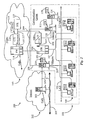
- Fig. 1 is an architectural overview of a communication center and connected network 100 wherein resource sharing is practiced according to an embodiment of the present invention.
- Communication network 100 comprises a multi-tenant communication center 101 and the well-known PSTN network 113.
- PSTN 113 may instead be any private or public COST network.
- the inventor chooses PSTN 113 for illustration in this example because of its high public-access characteristic.
- PSTN 113 has a telephony switch (SW) 114 illustrated therein and adapted as a local call switch such as an automatic call distributor (ACD) or, perhaps a private branch exchange (PBX) type telephony switch.
- ACD automatic call distributor
- PBX private branch exchange
- switch 114 may be part of a service control point (SCP).
- SCP service control point
- Switch 114 is, in this example, CTI-enabled by virtue of a CTI processor 116 connected thereto by a CTI link 115.
- Processor 116 is illustrated herein as supporting an instance of a transaction server (TS) and an instance of IVR represented in this example by the element number 118.
- TS transaction server
- IVR represented in this example by the element number 118.
- TS/IVR 118 may, in one embodiment, be provided as software on an adjunct peripheral connected to CTI processor 116. In another embodiment, TS/IVR 118 may be supported on two separate and dedicated peripherals connected to CTI processor 116, one peripheral dedicated to IVR function and one to TS function. There are many possible architectures.
- Switch 114 represents a last stop in PSTN 113 for calls, represented herein by a vector labeled Calls, destined for center 101. It will be appreciated that there will be many more telephony switches and other carrier equipment and connections than is illustrated in this simplified example. The inventor illustrates only one switch and CTI capability and deems such illustration sufficient for explanation of the present invention. CTI enhancement to switch 114 is not specifically required in order to successfully practice the present invention as long as the capability is at least provided as enhancement to a connected communication-center switch.
- communication center 101 is a multi-tenant center, meaning that a plurality of enterprises share communication-center telephony resources and architecture.
- a central telephony switch ( SW ) 105 is illustrated within communication center 101 and adapted as a central office-type telephony switch for internal call distribution within center 101.
- Switch 105 is connected to switch 114 within PSTN 113 via at least one COST telephony trunk 106.
- a CTI processor 108 is illustrated within center 101 and is connected to switch 105 via a CTI link 107.
- Processor 108 is adapted to support an instance of TS/IVR 112 as was described with reference to processor 116 and TS/IVR 118 of PSTN 113.
- Processor 108 is connected to processor 116 by a digital data network 117 separate and distinct from telephony trunk 106.
- This illustrated CTI architecture is known to the inventor and implemented for the purpose of enabling intelligent routing routines and other controls to be initiated at switch 114 within PSTN 113. Such controls and routines are provided to switch 114 from within communication center 101 or from within other associated communication centers (not shown).
- CTI and TS/IVR enhancement at both telephony switches 114 and at 105 are that information about callers can be passed to communication center 101 ahead of actual routed calls.
- Other benefits include agent-level-routing capabilities at network level and passing agent status information to network level before calls are routed, such as during IVR interaction with callers.
- Communication center 101 has an operator center 103 provided therein having agent stations manned with agents representing tenants of the center.
- Each agent station within an operator center 103 has at least a personal computer and a telephone.
- Each personal computer within region 103 is illustrated as connected to a local-area-network (LAN) 102.
- the agent telephones illustrated within domain 103 are connected to central switch 105 by way of internal telephony wiring 104.
- Communication center 101 is illustrated in this example as a COST communication center. Cost calls (represented by vector Calls within PSTN 113) arriving at switch 114 are routed to switch 105 within communication center 101. Call connections are established over telephone wiring 104 to appropriate agent telephones within domain 103. Information about callers appears in a monitor-displayed format on appropriate ones of agent computers within domain 103, the information arriving thereto by way of LAN 102.
- the IVR portion of TS/IVR 112 is separated or channeled such that a single channel may be dedicated as a resource for a single tenant of communication center 101.
- the described separation is not illustrated in this example, but is further decribed in enabling detail later in this specification.
- a novel intermediary server (I-Server) 110 is provided within communication center 101 and illustrated as connected to TS/IVR 112 by a data link 109.
- a novel virtual T-server (VT-Server) 114 is provided within communication center 101 and illustrated as connected directly to I-server 110 by a data link 120.
- VT-server 114 is illustrated as further connected to LAN 102 within communication center 101 and therefore accessible to agents operating within domain 103.
- the TS portion of TS/IVR 112 represents transaction server software adapted to control switch 105 according to communication-center routing capabilities.
- the TS portion of TS/IVR 118 within PSTN 113 is similarly adapted to control switch 114 at network level. It will be appreciated that certain routines and controls executed within PSTN 113 over switch 114 vary somewhat from those executed within communication center 101 over switch 105. However, TS software represented by elements 118 and 112 provide the main intelligence for routing calls within PSTN 113 and in communication center 101.
- VT-server 114 has an instance of software (SW) 119 installed thereon and configured to provide virtual routing and transaction intelligence that can be manipulated and personalized by individual tenants of communication center 101.
- SW 119 is equally partitioned or provided in separate instances in accordance with the number of subscribing tenants operating within communication center 101. For example, if there are 4 tenants operating within communication center 101 than there are 4 instances of SW 119, one instance per tenant.
- SW 119 is configurable per instance and communicates with TS/IVR 112 and/or TS/IVR 118 through I-server 110 acting as an intermediary mapping server.
- I-server 110 has a software instance (SW) 111 installed therein and adapted to broker communication and map communication paths between individual tenants of communication center 101 and TS/IVR functionalities 112 and/or 118.
- SW software instance
- Each individual tenant's instance of SW 119 within the VT-server 114 by way of LAN 102 and tenant software (SW) applications a-n is illustrated herein as distributed to agent computers within domain 103.
- SW applications a-n provide respective agents representing tenants of communication center 101 with the capability of logging into VT-server 114 and subscribing to their personal instance of SW 119.
- IVR function (112) is channeled such that at least one channel is dedicated to a single tenant.
- I-server 110 by virtue of SW 111 maps dedicated IVR channels to appropriate instances of VT-server (SW) 119 subscribed to by the tenants.
- SW VT-server
- Agents representing the tenants operating SW applications a-n in this example, Login and receive their telephony transactions through respective VT-server instances 119.
- Using the architecture and software instances as described in this example enables the shared resources to remain generic at higher level but personalized at an agent level. For example, an agent within domain 103 operating SWa can access his or her dedicated VT-server and make changes in routing rules and IVR specifics provided the generic forms of those capabilities are retained and TS/IVR 112 and/or TS/IVR 118. In this way all agents representing separate tenants may equally share main resources that still have personalization capability further individual portions of the total resource.
- a benefit of utilizing VT-server technology in terms of connection costs is that only one CTI link 107 is required to switch 105. Communication between servers 110, 114 and TS/IVR 112 is performed through machine-readable messaging. VT-server 114 does not require a CTI link to any telephony switch. Provision of completely separate and dedicated IVRs and transaction servers (individualized) to each of multiple tenants within a communication center is cost prohibitive in terms of added CTI links and other equipment. Providing a single IVR and transaction server that must be shared by all the tenants without benefit of the present invention is limited to generic capabilities practiced in the same way for all the tenants. The methods and apparatus of the present invention enable tenant personalization of routing and IVR interaction rules while still sharing the total resource with all the other tenants operating within the center.
- Fig. 1 represents just one simplified communication-center network practicing CTI-enabled COST telephony.
- the present invention is not limited to COST telephony as is discussed below.
- Fig. 2 is an architectural overview of a multi-capable communication center and connected network 200 wherein resource sharing is practiced according to a somewhat more complex embodiment of the present invention.
- Network 200 comprises the well-known PSTN network 113, communication center 101, and the well-known Internet network 202.
- Communication center 101 is enhanced in this example with equipment and software in enabling Internet-protocol-network-telephony (IPNT), including connection-oriented, switched IP telephony using SIP.
- IPNT Internet-protocol-network-telephony
- Communication center 101 is also capable of handling COST telephony as was described with reference to Fig. 1 above. Therefore, many components illustrated in this example shall retain the same element numbers of their counterparts represented with respect to Fig. 1.
- Telephony switch 114 illustrated within PSTN 113 accepts calls sourced from anywhere within PSTN 113 as illustrated by vector labeled Calls.
- CTI processor 116 provides CTI enhancement to switch 114 by way of CTI link 115.
- IVR capability is now shown separately from TS 118 and is now labeled with element number 211.
- IVR 211 is an adjunct peripheral connected to CTI processor 116 by way of a CTI link 117 in this embodiment.
- the main difference between this PSTN architecture and that described with reference to Fig. 1 is simply that IVR 211 is now provided as a separate machine running IVR software.
- Switch 114 routes calls destined to communication center 101 over telephony trunk 106 to central switch 105 as previously described.
- Switch 105 in communication center 101 is CTI-enabled by virtue of processor 108 connected thereto by CTI link 107.
- IVR 210 represents the only IVR functionality for COST callers attempting to reach center 101.
- Processor 108 provides CTI enhancement and TS functionality to switch 105.
- Processor 116 and IVR 119 share a data-network connection 209 to processor 108 within communication center 101. The inventor intends to illustrate by the absence of IVR functionality within center 101 that practice of the present invention does not depend on where or how the IVR resource is connected to work in association with the communication center.
- Internet network 202 comprises an Internet backbone 201, which represents all of the lines, equipment and connection points that make up the Internet network as a whole. Therefore there are no geographic limitations to the practice of the present invention.
- Am Internet server 203 is illustrated within network 202 and adapted as a data-network access point for network customers attempting to contact communication center 101 by way of, in this example, the Internet.
- Server 203 is illustrated connected to backbone 201.
- Incoming calls to server 203 are represented herein by a vector labeled Calls.
- Server 203 may be hosted by the enterprises, or any one of them, hosting communication center 101. Interaction with communication center 101, in this example, involves both COST telephony and IPNT.
- Switch 105 is connected to agent telephones within domain 103 via telephone wiring 104 as was the case with respect to Fig. 1.
- An Internet router ( I-Router ) 207 is provided within communication center 101 and adapted as an Internet protocol (IP data router). Router 207 is connected to server 203 by way of an Internet access line 205. All communication events sourced from Internet 202 arrive at router 207 before internal routing to agents. Router 207 is illustrated as connected to LAN 102 but this is not specifically required in order to successfully practice the present invention. Direct connection to LAN 102 represents a convenience in that router 207 handles e-mails, electronic faxes, as well as live data-network-telephony (DNT).
- DNT live data-network-telephony
- Router 207 has an instance of IVR/TS software 210 installed thereon and adapted as a DNT version of the software used in conjunction with COST networks. Therefore, router 207 has voice interaction capability as well as intelligent routing capability. Router 207 is illustrated as connected to I-server 110 by a data link 206. Similarly, CTI processor 108 is connected to server 110 by a data link 208. In this example, server 110 by virtue of SW 111 is capable of mapping a plurality of channels associated with IVR 211 within PSTN 113 and a plurality of channels associated with IVR 210 to appropriate VT-server instances 119 in server 114. In this case, each agent operating within domain 103 using SW instances a-n subscribes to his or her own VT application and now has personalized DNT and COST routing and IVR interaction capabilities.
- Router 207, server 110, and server 114 communicate with each other using machine-readable messaging capabilities.
- machine-readable messaging capabilities There are many applicable messaging protocols known in the art, some of which are also human readable and can also be used.
- each grouping of computer and telephone (agent station) within domain 103 represents a singular tenant, then there are four tenants in this example.
- Each of the 4 tenants may have different routing and IVR implementations than those of their counterparts.
- the only requirement is that the personalized building blocks are applicable to the generic construction and configuration of the main IVR and TS resource.
- each telephone within domain 103 is connected to its associated computer using a telephone-to-soundcard connection. In this way IPNT events may also be answered using the telephone.
- telephones in this example are multi-capable as well.
- agents representing tenants operating within domain 103 may utilize SW instances a-n for the purpose personalizing their IVR presentations and T-server functions.
- IVR resources may be implemented in a software or in hardware sense without departing from the spirit and scope of the present invention.
- separate instances of VT-server application 119 may be provided in separate hardware structures for security reasons, or maybe software divided or created within one machine.
- software instances a-n residing on respective computers and domain 103 may function as VT-server applications thereby eliminating the need for VT- server 114.
- I-server 110 would be directly connected to LAN 102. There are many possibilities.
- Fig. 3 is a block diagram illustrating NR resource partition and mapping according to an embodiment of the present invention.
- multiple separate IVRs may be provided within a communication center and linked to telephony resources within the PSTN or other COST network.
- an IVR 302 is provided having separate IVR channels a-n communicating through an IVR driver 306 and data trunk to an I-server 309.
- IVRs b-n also ported to I-server 309.
- IVRs b-n are presumed to be identical to IVR (302) having drivers analogous to driver 306 and a plurality of IVR channels a-n.
- the IVR resource is scalable simply by adding new machines and linking them into the PSTN network, typically, to a local telephony switch analogous to switch 114 of Fig. 1.
- TS and CTI switching resources are hosted within the PSTN and not illustrated. There may or may not be IVR resources present within PSTN 301.
- a plurality of virtual T-servers a-n is illustrated as ported to I-server 309 on its opposite side of IVR ports.
- virtual T-servers a-n are associated with IVR channels a-n of IVR 302. If this is true, IVRs b-n represent unused resources.
- I server 309 by virtue of software as previously described maps each IVR channel to its appropriate VT-server. If any IVR channel assignment is changed to a new tenant and therefore a new VT-server, I-server 309 keeps track of the update. Similar to a router, I-server 309 routes messages from the VT-server side to the IVR side and in reverse order.
- IVR channels for example, and IVR 302 are software channels and only one port is required I server 309.
- a separate port is utilized for each VT-server, however this is not required to practice the present invention as VT-server software may be partitioned into dedicated portions running on one machine. Similarly, additional VT-server instances may be added or subtracted according to need without hard wiring.
- One VT-server handles telephony processing for one tenant.
- well-known soft-switch protocols may be used for messaging such as H.323, session-initiated protocol (SIP), or voice-over-eXtensibile-Markup Language (VoXML).
- CTI and T-server resources are hosted within PSTN 301 as previously described above.
- tenant dependent information TDI
- This information may include dialed-number-identification-service (DNIS), and account number, or other information that may be used to identify an appropriate VT-server to handle the event.
- DNIS dialed-number-identification-service
- caller information and information solicited by IVR may also be embedded into the messaging.
- Internal routing will be based in part on the VT handling of events based on IVR interaction and, of course, on availability of an agent of the tenant to which the call is intended. It is possible that messaging is propagated back and forth between network level (CTI/TS) and VT resource through I-server 309 for the purpose of determining final routing.
- CTI/TS network level
- IVR resources are enhanced with a capability for accepting change orders from tenants through VT-server applications and communicating those orders to PSTN-hosted CTI and TS resources.
- Fig. 4 is a block diagram illustrating IVR resource partition and mapping according to yet another embodiment of the present invention.
- the IVR, I-server, and VT-server components are identical to those described with reference to Fig. 3 above and therefore shall not be reintroduced.
- Additional components in this example include a CTI-linked T-server 403 illustrated herein as connected to I-server 309 by a datalink 404.
- T-server 403 is presumed analogous to processor 108 described with reference to Fig. 1 of this specification.
- T-server 403 is illustrated herein as connected to a switch 401 by a CTI link 402.
- Switch 401 is presumed analogous to a central telephony switch similar to switch 105 described with reference to Fig. 1 and Fig. 2.
- I-server 309 may separate IVR function and TS function with respect to organization and communication. For example, when a telephony event arrives at switch 401 and is routed to a particular IVR channel for interaction, TS data, caller information, and destination information, may be routed to I-server 309 from switch 401 over CTI link 402 and through T-server 403. A plurality of messages may be sent back and forth between I-server 309 and switch 401 over the main CTI link (402) during IVR interaction and before final routing determination is made. All intelligent routing routines that may be available within a communication center are applicable in this embodiment. In this case, IVR resources a-n may be implemented as dedicated IVR resources requiring no enhancement or modification in order to practice the present invention.
- mapping information including tenant identification (static), IVR channel identification (static), caller identification (dynamic), and so on is continually updated and maintained within I-server 309 for each call event on behalf of a communication center tenant.
- a tenant's VT-server application is notified when it must process an incoming call and responds appropriately with correct final routing determination.
- tenant status in terms of machine location of agents representing the tenant within the communication center or availability of an agent or agents with respect to multiple tasks, such information may be updated dynamically to I-server 309 for mapping purposes.
- FIG. 5 is an architectural overview of a virtual communication-center and connected network 500 wherein resource sharing is practiced according to yet another embodiment of the invention.
- Communication center 101 in this example, is a virtual communication center meaning that there are no agents or operators answering calls physically within the center.
- Tenants subscribing to virtual communication center 101 are represented in this example as remote agents 501 a-n.
- Each agent's equipment group comprising, essentially, a computer and connected telephone is Internet-capable.
- Software (SW) applications a-n illustrated in this example are distributed on respective agent computers within cloud 501 a-n the same manner as was described with reference to Figs.1 and 2.
- Each tenant or agent a-n represented within cloud 501 has an Internet connection to an Internet service provider (ISP) 503 as is illustrated logically herein by connection lines drawn from individual agents phones to ISP 503 within PSTN 113.
- ISP Internet service provider
- ISP 503 is adapted to provide Internet services for remote agents 501 a-n. Although it is not shown in this example, ISP 503 may be presumed to contain a telephone modem bank as well as an Internet connection server. In this example, ISP 503 is connected to telephony switch 114 within PSTN 113 by way of telephony trunk. ISP 503 is also directly connected to Internet backbone 201 by way of an Internet access line 506. Switch 114 also has a connection to a network bridge 502 that is adapted to convert calls between Internet 202 and PSTN 113 and reverse order.
- calls may reach virtual communication center 101 from anywhere in PSTN 113 as represented by the vector labeled Calls.
- access to communication center 101 may be achieved by calling from anywhere within Internet 202, incoming calls also represented by vector labeled Calls.
- Internet callers may place a COST call to communication center 101 from Internet 202 through bridge 502 and into PSTN 113.
- PSTN callers may initiate DNT calls through a network bridge 502 and subsequently Internet network 202. This example represents seamless telephony practiced between the disparate networks of PSTN 113 and Internet 202 from the viewpoint of virtual communication center 101.
- tenants or agents 501 a-n subscribe to their VT-server applications (SW 119) through ISP 503 and either a PSTN (113) route or an Internet (202) route.
- a customer-information-server (CIS) is provided and illustrated as connected to LAN 102 of communication center of 101.
- CIS server 505 contains information about customers such as account number, contact information, purchase histories, and other conceivable types of useful information.
- I-server, I-router, and VT-server is virtually identical to the configuration shown with respect to communication center 101 of Fig. 2.
- the difference in this example is that there are no LAN-connected tenants (agents) within center 101 to except routed calls.
- all communication events detected are routed in an outbound sense to agents 501 a-n through a PSTN outbound path or through an Internet outbound path.
- tenant 501b has pending COST telephony events detected at VT-server 114, those events may be routed from switch 105 over trunk 106 into switch 114, through ISP 503, and to the telephone of tenant b. This presumes that the original call or calls were actually routed from switch 114 into switch 105.
- call-notifications are routed to switch 105 where they may be detected by server 114 and the appropriate VT-server application 119. It is noted herein that in this example, COST IVR resource (211) is hosted within PSTN 113.
- DNT events originating within Internet 202 at server 203 may be routed over Internet access line 205 into I-router or 207 were IVR interaction may occur by virtue of SW 210 having IVR and TS functionality.
- Live IPNT calls are routed back through server 203 and on to backbone 201, over Internet pipeline 506 to ISP 503, and on to an appropriate agent 501 a-n.
- agents or tenant within group 501 may receive I PNT calls on their COST telephones.
- live events are routed through a network bridge 502 and into telephone switch 114 and routed on to agents COST phones either through ISP 503 or directly over standard POTS telephony lines.
- the fact that agents representing tenants operate remotely enables communication center 101 to cut further costs associated with agent equipment and LAN connections.
Landscapes
- Business, Economics & Management (AREA)
- Marketing (AREA)
- Engineering & Computer Science (AREA)
- Signal Processing (AREA)
- Data Exchanges In Wide-Area Networks (AREA)
- Telephonic Communication Services (AREA)
- Exchange Systems With Centralized Control (AREA)
- Financial Or Insurance-Related Operations Such As Payment And Settlement (AREA)
Claims (33)
- Transaktionsserversystem zum Routen und Bearbeiten von Telephonieereignissen in einem Multi- Tenant Kommunikationszentrum (101), umfassend einen CTI- fähigen Routingpunkt, der eine Transaktionsserversoftware (112; 118) benutzt und eine Vielzahl von Anschlusspunkten aufweist, die mit einer interaktiven Sprachdialog- (IVR) (112; 119) Ressource zum Empfangen und Ankündigen von Telephonieereignissen entsprechend den Anschlusspunkten ausgestattet sind, dadurch gekennzeichnet, dass das Transaktionsserversystem eine Vielzahl von virtuellen Transaktionsserveranwendungen (119) umfasst, verknüpft mit je einem Anschlusspunkt für das Erledigen anhängiger Telephonieereignisse entsprechend eingeführten Protokollen, und einen Zwischenserver (110), angeordnet zwischen den IVR (112; 118) Ressourcen und damit verbunden und mit der Vielzahl von virtuellen Transaktionsserveranwendungen (119), wobei der Zwischenserver (110) das Kartieren von Kommunikationspfaden zwischen den einzelnen aus der Vielzahl der Anschlusspunkte der IVR (112; 119) Ressourcen zu den einzelnen aus der Vielzahl der virtuellen Transaktionsserveranwendungen (119) ermöglicht, und wobei jede virtuelle Transaktionsserveranwendung (119) die Ereignisbearbeitung im Auftrag wenigstens eines der Nutzer des Multi- Tenant Kommunikationszentrums (101) ermöglicht.
- Transaktionsserversystem nach Anspruch 1, wobei der CTIfähige Routingpunkt ein Telefonieswitch (114) ist, der in einem Telefonnetzwerk (113) eingerichtet ist.
- Transaktionsserversystem nach Anspruch 1, wobei der CTIfähige Routingpunkt ein Telefonieswitch (105) ist, der in dem Multi- Tenant Kommunikationszentrum (101) eingerichtet ist.
- Transaktionsserversystem nach Anspruch 1, wobei der CTIfähige Routingpunkt ein Internetprotokollrouter (207) ist, der im Internet (202) eingerichtet ist.
- Transaktionsserversystem nach Anspruch 1, wobei der CTIfähige Routingpunkt ein Internetprotokollrouter (207) ist, der in dem Multi- Tenant Kommunikationszentrum (101) eingerichtet ist und mit dem Internet (202) verbunden ist.
- Transaktionsserversystem nach Anspruch 1, wobei die Vielzahl der Anschlusspunkte nutzerspezifische Hardwareports der IVR (112; 118) Ressourcen sind, die mit dem Routingpunkt verknüpft sind.
- Transaktionsserversystem nach Anspruch 1, wobei die Vielzahl der Anschlusspunkte nutzerspezifische Softwarekanäle der IVR (112; 118) Ressourcen sind, die mit dem Routingpunkt verknüpft sind.
- Transaktionsserversystem nach Anspruch 1, wobei das Multi- Tenant Kommunikationszentrum (101) in der Lage ist, verbindungsorientiert vermittelte Telefonie COST- (=Connection Oriented Switched Telephony) Transaktionen zu bearbeiten.
- Transaktionsserversystem nach Anspruch 1, wobei das Multi- Tenant Kommunikationszentrum (101) in der Lage ist, Internet- Protokoll- Netzwerk- Telefonie IPNT- Transaktionen zu bearbeiten.
- Transaktionsserversystem nach Anspruch 1, wobei das Multi- Tenant Kommunikationszentrum (101) in der Lage ist, sowohl verbindungsorientiert vermittelte Telefonie COST- als auch Internet- Protokoll- Netzwerk- Telefonie IPNT-Transaktionen zu bearbeiten.
- Transaktionsserversystem nach Anspruch 1, wobei die virtuellen Transaktionsserveranwendungen (119) konfigurierbar sind, wobei die Konfigurationen für erfolgreiche Funktion von der Haupttransaktionsserver- Softwarestruktur abhängen.
- Mappingserver (110) zum Kartieren und Aufbauen geeigneter Kommunikationspfade zwischen den nutzerspezifischen Multi-Tenant Anschlusspunkten einer interaktiven Sprachdialog-(IVR) (112; 118) Ressource und nutzerspezifischen Multi-Tenant Transaktionsserveranwendungen (119) in einer Multi-Tenant Kommunikationszentrums-Umgebung (101), bestehend aus:wenigstens einem bidirektionalen Port zum Aufbau von Kommunikation mit wenigstens einer Maschine, die die Vielzahl der Anschlusspunkte versorgt;wenigstens einem bidirektionalen Port zum Aufbau von Kommunikation mit wenigstens einer Maschine, auf der die Vielzahl der Transaktionsserveranwendungen (119) ablaufen; undeine Softwaretabelle, die auf dem Server (110) eingerichtet ist zur Aktualisierung und Verfolgung der Kartierungsaufträge zwischen den zugeordneten Anschlusspunkten und den Transaktionsserveranwendungen (119).
- Mappingserver (110) nach Anspruch 12, der mit einem CTIfähigen Routingpunkt verbunden ist, der einen Telefonieswitch (114) enthält, der in einem Telefonnetzwerk (113) angeordnet ist.
- Mappingserver (110) nach Anspruch 12, der mit einem CTIfähigen Routingpunkt verbunden ist, der einen Telefonieswitch (105) enthält, der in einem Multi- Tenant Kommunikationszentrum (101) angeordnet ist.
- Mappingserver (110) nach Anspruch 12, der mit einem CTIfähigen Routingpunkt verbunden ist, der einen Internetprotokollrouter (207) umfasst, der im Internet (201) Netzwerk eingerichtet ist.
- Mappingserver (110) nach Anspruch 12, der mit einem CTIfähigen Routingpunkt verbunden ist, der einen Internetprotokollrouter umfasst, der im Multi- Tenant Kommunikationszentrum (101) eingerichtet ist und mit dem Internet (201) verbunden ist.
- Mappingserver (110) nach Anspruch 12, wobei die Vielzahl der Anschlusspunkte nutzerspezifische Hardwareports der IVR (112; 118) Ressourcen sind, die mit einem Routingpunkt verknüpft sind.
- Mappingserver (110) nach Anspruch 12, wobei die Vielzahl der Anschlusspunkte nutzerspezifische Softwarekanäle der IVR (112; 118) Ressourcen sind, die mit einem Routingpunkt verknüpft sind.
- Transaktionsserversystem nach Anspruch 11, wobei die virtuellen Transaktionsserveranwendungen (119) konfigurierbar sind durch individuelle Desktopsoftware- Anwendungen (SWa, SWb, SWc, SWn), die auf Computern eingerichtet sind, die für LAN (102) Technologie ausgerüstet sind.
- Mittel zum Bereitstellen von Softwareanwendungen zur Emulation von Transaktionsserverfunktionen in einem CTIfähigen Kommunikationszentrum (101), umfassend:einen Anteil für das Empfangen von Kommunikationsereignisankündigungen und für das Konsultieren der Haupttransaktionsprotokolle;einen Anteil für das Formulieren und Aufbauen eines weitergehend definierten Satzes von Transaktionsprotokollen auf Basis der Haupttransaktionsprotokolle, undeinen Anteil für das Formulieren und Ausführen von Transaktionsaufträgen auf Basis des weitergehend definierten Satzes von Transaktionsprotokollen; undeinen Anteil für das Ermöglichen von Änderungen an dem weitergehend definierten Satz von Transaktionsprotokollen.
- Softwareanwendung nach Anspruch 20, wobei alle Anteile auf einer einzigen Maschine (114) untergebracht sind.
- Softwareanwendung nach Anspruch 20, wobei die Anteile getrennt und strategisch verteilt werden, um auf mehr als einer Maschine ausgeführt zu werden.
- Softwareanwendung nach Anspruch 20, wobei eine der Maschinen ein Personal Computer ist, der LAN (102)- und TCP/IP- fähig ist und im Kommunikationszentrum (101) eingerichtet ist.
- Softwareanwendung nach Anspruch 20, wobei eine der Maschinen ein Personal Computer ist, der entfernt vom Kommunikationszentrum (101) angeordnet ist und mit diesem verbunden werden kann bei Benutzung des Internet (202) Netzwerks.
- Verfahren zum gemeinsamen Nutzen von interaktiven Sprachdialog- (IVR) (112; 118) Ressourcen in einem Multi-Tenant Kommunikationszentrum (101), das folgende Schritte umfasst:a) Aufteilen der Sprachdialog- (IVR) (112; 118) Ressourcen auf getrennte Anschlusspunkte, die jeweils einem pro Nutzer zugeordnet werden;b) Bereitstellen von individuell zugeteilten und spezifischen Nutzeranwendungen, die in der Lage sind, die (IVR) (112; 118) Ressourcen zu nutzen;c) Bereitstellen einer Zwischen- Mappinganwendung (111) zum Verbinden einzelner der Anschlusspunkte, die mit den (IVR) (112; 118) Ressourcen verknüpft sind mit einzelnen der Nutzeranwendungen für die Kommunikation von Ereignisankündigungen und Anruf- Dispositionsbefehlen.
- Verfahren nach Anspruch 25, wobei das Multi- Tenant Kommunikationszentrum (101) ein verbindungsorientiertes Switched Telephoniezentrum COST ist.
- Verfahren nach Anspruch 25, wobei beim Schritt a) die (IVR) (112; 118) Ressourcen mit Transaktionsserver- Ressourcen (112; 118) kombiniert werden, und das Multi- Tenant Kommunikationszentrum (101) ein verbindungsorientiertes Switched Telephoniezentrum COST ist.
- Verfahren nach Anspruch 25, wobei beim Schritt a) die Anschlusspunkte Hardware- IVR Ports sind.
- Verfahren nach Anspruch 25, wobei beim Schritt a) die Anschlusspunkte Software- IVR Kanäle sind.
- Verfahren nach Anspruch 25, wobei beim Schritt a) das Multi- Tenant Kommunikationszentrum (101) ein Internet-Protokoll- Netzwerk- Telefonie IPNT- Zentrum ist.
- Verfahren nach Anspruch 30, wobei beim Schritt a) die Anschlusspunkte Software- IVR Kanäle sind.
- Verfahren nach Anspruch 25, wobei beim Schritt b) die Nutzeranwendungen virtuelle Transaktionsserveranwendungen (119) sind, die von einer Haupttransaktionsserveranwendung abhängen.
- Verfahren nach Anspruch 25, wobei beim Schritt c) die Kommunikation wenigstens das Senden von Ankündigungen von Telephonieereignissen umfasst und von Parametern, die von den Nutzeranwendungen entsprechend von Anrufdispositionsregeln eingesetzt werden.
Applications Claiming Priority (3)
| Application Number | Priority Date | Filing Date | Title |
|---|---|---|---|
| US912770 | 2001-07-24 | ||
| US09/912,770 US6788779B2 (en) | 2001-07-24 | 2001-07-24 | Method and apparatus for routing calls by proxy using virtual transaction servers in a multi-tennant communication center |
| PCT/US2002/023080 WO2003010948A1 (en) | 2001-07-24 | 2002-07-19 | Method and apparatus for routing calls by proxy using virtual transaction servers in a multi-tenant communication center |
Publications (3)
| Publication Number | Publication Date |
|---|---|
| EP1410614A1 EP1410614A1 (de) | 2004-04-21 |
| EP1410614A4 EP1410614A4 (de) | 2005-07-06 |
| EP1410614B1 true EP1410614B1 (de) | 2006-08-23 |
Family
ID=25432414
Family Applications (1)
| Application Number | Title | Priority Date | Filing Date |
|---|---|---|---|
| EP02756535A Expired - Lifetime EP1410614B1 (de) | 2001-07-24 | 2002-07-19 | Verfahren und vorrichtung zum routen von anrufen durch proxy unter verwendung virtueller transaktionsserver in einer mehrmieter-kommunikationszentrale |
Country Status (5)
| Country | Link |
|---|---|
| US (3) | US6788779B2 (de) |
| EP (1) | EP1410614B1 (de) |
| AT (1) | ATE337678T1 (de) |
| DE (1) | DE60214191T2 (de) |
| WO (1) | WO2003010948A1 (de) |
Cited By (11)
| Publication number | Priority date | Publication date | Assignee | Title |
|---|---|---|---|---|
| US8971216B2 (en) | 1998-09-11 | 2015-03-03 | Alcatel Lucent | Method for routing transactions between internal and external partners in a communication center |
| US9002920B2 (en) | 1998-09-11 | 2015-04-07 | Genesys Telecommunications Laboratories, Inc. | Method and apparatus for extended management of state and interaction of a remote knowledge worker from a contact center |
| US9008075B2 (en) | 2005-12-22 | 2015-04-14 | Genesys Telecommunications Laboratories, Inc. | System and methods for improving interaction routing performance |
| USRE45583E1 (en) | 1999-12-01 | 2015-06-23 | Genesys Telecommunications Laboratories, Inc. | Method and apparatus for providing enhanced communication capability for mobile devices on a virtual private network |
| USRE45606E1 (en) | 1997-02-10 | 2015-07-07 | Genesys Telecommunications Laboratories, Inc. | Call and data correspondence in a call-in center employing virtual restructuring for computer telephony integrated functionality |
| USRE46060E1 (en) | 1997-02-10 | 2016-07-05 | Genesys Telecommunications Laboratories, Inc. | In-band signaling for routing |
| USRE46153E1 (en) | 1998-09-11 | 2016-09-20 | Genesys Telecommunications Laboratories, Inc. | Method and apparatus enabling voice-based management of state and interaction of a remote knowledge worker in a contact center environment |
| US9516171B2 (en) | 1997-02-10 | 2016-12-06 | Genesys Telecommunications Laboratories, Inc. | Personal desktop router |
| US9553755B2 (en) | 1998-02-17 | 2017-01-24 | Genesys Telecommunications Laboratories, Inc. | Method for implementing and executing communication center routing strategies represented in extensible markup language |
| USRE46438E1 (en) | 1999-09-24 | 2017-06-13 | Genesys Telecommunications Laboratories, Inc. | Method and apparatus for data-linking a mobile knowledge worker to home communication-center infrastructure |
| USRE46528E1 (en) | 1997-11-14 | 2017-08-29 | Genesys Telecommunications Laboratories, Inc. | Implementation of call-center outbound dialing capability at a telephony network level |
Families Citing this family (32)
| Publication number | Priority date | Publication date | Assignee | Title |
|---|---|---|---|---|
| US6785710B2 (en) * | 1998-06-22 | 2004-08-31 | Genesys Telecommunications Laboratories, Inc. | E-mail client with programmable address attributes |
| US6788779B2 (en) * | 2001-07-24 | 2004-09-07 | Genesys Telecommunications Laboratories, Inc. | Method and apparatus for routing calls by proxy using virtual transaction servers in a multi-tennant communication center |
| DE10114208A1 (de) * | 2001-03-23 | 2002-05-08 | Trw Automotive Safety Sys Gmbh | Gassack-Modul |
| EP1563628A4 (de) | 2002-11-06 | 2010-03-10 | Ibm | Gemeinsame benutzung vertraulicher daten und auflösung anonymer entitäten |
| US7372957B2 (en) * | 2002-12-24 | 2008-05-13 | Intel Corporation | Method and apparatus for implementing call processing in packet telephony networks |
| US20050163136A1 (en) * | 2003-11-17 | 2005-07-28 | Leo Chiu | Multi-tenant self-service VXML portal |
| US7697673B2 (en) | 2003-11-17 | 2010-04-13 | Apptera Inc. | System for advertisement selection, placement and delivery within a multiple-tenant voice interaction service system |
| US7474746B2 (en) * | 2004-04-09 | 2009-01-06 | Atris, Incorporated | Multi-user telephone system |
| US8155014B2 (en) * | 2005-03-25 | 2012-04-10 | Cisco Technology, Inc. | Method and system using quality of service information for influencing a user's presence state |
| US8015403B2 (en) | 2005-03-28 | 2011-09-06 | Cisco Technology, Inc. | Method and system indicating a level of security for VoIP calls through presence |
| US7764779B2 (en) * | 2005-05-06 | 2010-07-27 | Aspect Software, Inc. | SIP ACD multi-tenant mechanism that facilitates multiple levels of partitions or tenants |
| US7764699B2 (en) * | 2005-05-16 | 2010-07-27 | Cisco Technology, Inc. | Method and system using shared configuration information to manage network access for network users |
| US7920847B2 (en) * | 2005-05-16 | 2011-04-05 | Cisco Technology, Inc. | Method and system to protect the privacy of presence information for network users |
| US8079062B2 (en) * | 2005-05-16 | 2011-12-13 | Cisco Technology, Inc. | Method and system using presence information to manage network access |
| US20070047531A1 (en) * | 2005-08-26 | 2007-03-01 | Stmicroelectronics Asia Pacific Pte, Ltd. | System and method for implementing proxy independent hunt group function in a packet based network |
| US8774371B1 (en) * | 2005-12-17 | 2014-07-08 | O'hanlon Ltd | Dynamic multiple server interactive response system |
| US8204213B2 (en) * | 2006-03-29 | 2012-06-19 | International Business Machines Corporation | System and method for performing a similarity measure of anonymized data |
| US8204831B2 (en) | 2006-11-13 | 2012-06-19 | International Business Machines Corporation | Post-anonymous fuzzy comparisons without the use of pre-anonymization variants |
| US7852783B2 (en) * | 2006-12-07 | 2010-12-14 | Cisco Technology, Inc. | Identify a secure end-to-end voice call |
| US8412809B2 (en) * | 2007-10-24 | 2013-04-02 | International Business Machines Corporation | Method, apparatus and computer program product implementing multi-tenancy for network monitoring tools using virtualization technology |
| US10033869B2 (en) * | 2008-08-29 | 2018-07-24 | 8X8, Inc. | Methods and systems for information streaming to user interface |
| US20110178946A1 (en) * | 2010-01-15 | 2011-07-21 | Incontact, Inc. | Systems and methods for redundancy using snapshots and check pointing in contact handling systems |
| US8594280B1 (en) * | 2010-02-03 | 2013-11-26 | Zvi Or-Bach | Systems and methods for visual presentation and selection of IVR menu |
| US8477926B2 (en) * | 2010-04-16 | 2013-07-02 | Bolder Thinking Communications, Inc. | Cloud computing call centers |
| US8699674B2 (en) | 2010-04-21 | 2014-04-15 | Angel.Com Incorporated | Dynamic speech resource allocation |
| US8917828B2 (en) | 2010-04-21 | 2014-12-23 | Angel.Com Incorporated | Multi-channel delivery platform |
| US8582727B2 (en) | 2010-04-21 | 2013-11-12 | Angel.Com | Communication of information during a call |
| US9031223B2 (en) | 2011-05-25 | 2015-05-12 | Echopass Corporation | Systems and methods for managing multi-tenant callback services |
| US9065916B2 (en) * | 2012-06-01 | 2015-06-23 | Callpromise, Llc | System and method for virtual queuing of calls |
| US9285974B2 (en) | 2014-02-28 | 2016-03-15 | Angel.Com Incorporated | Application builder platform |
| US9571636B2 (en) | 2014-12-31 | 2017-02-14 | Genesys Telecommunications Laboratories, Inc. | Call center builder platform |
| US10986479B2 (en) | 2018-01-17 | 2021-04-20 | Micro Focus Llc | Service management and provisioning for tenant service instances |
Family Cites Families (7)
| Publication number | Priority date | Publication date | Assignee | Title |
|---|---|---|---|---|
| US5790650A (en) * | 1994-06-01 | 1998-08-04 | Davox Corporation | Telephone call center management system which supports multi-user and separate private applications |
| US6175564B1 (en) * | 1995-10-25 | 2001-01-16 | Genesys Telecommunications Laboratories, Inc | Apparatus and methods for managing multiple internet protocol capable call centers |
| US6427002B2 (en) * | 1998-05-07 | 2002-07-30 | Worldcom, Inc. | Advanced interactive voice response service node |
| US6496567B1 (en) * | 1998-05-07 | 2002-12-17 | Mci Communications Corporation | Interactive voice response service node with advanced resource management |
| US6788779B2 (en) * | 2001-07-24 | 2004-09-07 | Genesys Telecommunications Laboratories, Inc. | Method and apparatus for routing calls by proxy using virtual transaction servers in a multi-tennant communication center |
| US7412422B2 (en) * | 2000-03-23 | 2008-08-12 | Dekel Shiloh | Method and system for securing user identities and creating virtual users to enhance privacy on a communication network |
| US6442247B1 (en) * | 2000-03-29 | 2002-08-27 | Genesys Telecommunications Laboratories, Inc. | Method and apparatus for recording and automated playback of personal agent greetings in a communication-center environment |
-
2001
- 2001-07-24 US US09/912,770 patent/US6788779B2/en not_active Expired - Lifetime
-
2002
- 2002-07-19 EP EP02756535A patent/EP1410614B1/de not_active Expired - Lifetime
- 2002-07-19 WO PCT/US2002/023080 patent/WO2003010948A1/en not_active Ceased
- 2002-07-19 DE DE60214191T patent/DE60214191T2/de not_active Expired - Lifetime
- 2002-07-19 AT AT02756535T patent/ATE337678T1/de not_active IP Right Cessation
-
2004
- 2004-07-26 US US10/899,528 patent/US7079641B2/en not_active Expired - Lifetime
-
2006
- 2006-07-11 US US11/456,796 patent/US7277536B2/en not_active Expired - Lifetime
Cited By (19)
| Publication number | Priority date | Publication date | Assignee | Title |
|---|---|---|---|---|
| US9516171B2 (en) | 1997-02-10 | 2016-12-06 | Genesys Telecommunications Laboratories, Inc. | Personal desktop router |
| USRE46243E1 (en) | 1997-02-10 | 2016-12-20 | Genesys Telecommunications Laboratories, Inc. | In-band signaling for routing |
| USRE45606E1 (en) | 1997-02-10 | 2015-07-07 | Genesys Telecommunications Laboratories, Inc. | Call and data correspondence in a call-in center employing virtual restructuring for computer telephony integrated functionality |
| USRE46060E1 (en) | 1997-02-10 | 2016-07-05 | Genesys Telecommunications Laboratories, Inc. | In-band signaling for routing |
| USRE46521E1 (en) | 1997-09-30 | 2017-08-22 | Genesys Telecommunications Laboratories, Inc. | Method and apparatus for extended management of state and interaction of a remote knowledge worker from a contact center |
| USRE46528E1 (en) | 1997-11-14 | 2017-08-29 | Genesys Telecommunications Laboratories, Inc. | Implementation of call-center outbound dialing capability at a telephony network level |
| US9553755B2 (en) | 1998-02-17 | 2017-01-24 | Genesys Telecommunications Laboratories, Inc. | Method for implementing and executing communication center routing strategies represented in extensible markup language |
| US9350808B2 (en) | 1998-09-11 | 2016-05-24 | Alcatel Lucent | Method for routing transactions between internal and external partners in a communication center |
| US9002920B2 (en) | 1998-09-11 | 2015-04-07 | Genesys Telecommunications Laboratories, Inc. | Method and apparatus for extended management of state and interaction of a remote knowledge worker from a contact center |
| USRE46153E1 (en) | 1998-09-11 | 2016-09-20 | Genesys Telecommunications Laboratories, Inc. | Method and apparatus enabling voice-based management of state and interaction of a remote knowledge worker in a contact center environment |
| USRE46387E1 (en) | 1998-09-11 | 2017-05-02 | Genesys Telecommunications Laboratories, Inc. | Method and apparatus for extended management of state and interaction of a remote knowledge worker from a contact center |
| US8971216B2 (en) | 1998-09-11 | 2015-03-03 | Alcatel Lucent | Method for routing transactions between internal and external partners in a communication center |
| US10218848B2 (en) | 1998-09-11 | 2019-02-26 | Genesys Telecommunications Laboratories, Inc. | Method and apparatus for extended management of state and interaction of a remote knowledge worker from a contact center |
| USRE46438E1 (en) | 1999-09-24 | 2017-06-13 | Genesys Telecommunications Laboratories, Inc. | Method and apparatus for data-linking a mobile knowledge worker to home communication-center infrastructure |
| USRE46457E1 (en) | 1999-09-24 | 2017-06-27 | Genesys Telecommunications Laboratories, Inc. | Method and apparatus for data-linking a mobile knowledge worker to home communication-center infrastructure |
| USRE45583E1 (en) | 1999-12-01 | 2015-06-23 | Genesys Telecommunications Laboratories, Inc. | Method and apparatus for providing enhanced communication capability for mobile devices on a virtual private network |
| USRE46538E1 (en) | 2002-10-10 | 2017-09-05 | Genesys Telecommunications Laboratories, Inc. | Method and apparatus for extended management of state and interaction of a remote knowledge worker from a contact center |
| US9008075B2 (en) | 2005-12-22 | 2015-04-14 | Genesys Telecommunications Laboratories, Inc. | System and methods for improving interaction routing performance |
| US9854006B2 (en) | 2005-12-22 | 2017-12-26 | Genesys Telecommunications Laboratories, Inc. | System and methods for improving interaction routing performance |
Also Published As
| Publication number | Publication date |
|---|---|
| DE60214191D1 (de) | 2006-10-05 |
| US20030021406A1 (en) | 2003-01-30 |
| US6788779B2 (en) | 2004-09-07 |
| EP1410614A4 (de) | 2005-07-06 |
| US20040264678A1 (en) | 2004-12-30 |
| US7277536B2 (en) | 2007-10-02 |
| EP1410614A1 (de) | 2004-04-21 |
| WO2003010948A1 (en) | 2003-02-06 |
| US7079641B2 (en) | 2006-07-18 |
| ATE337678T1 (de) | 2006-09-15 |
| DE60214191T2 (de) | 2006-12-28 |
| US20060245421A1 (en) | 2006-11-02 |
Similar Documents
| Publication | Publication Date | Title |
|---|---|---|
| US6788779B2 (en) | Method and apparatus for routing calls by proxy using virtual transaction servers in a multi-tennant communication center | |
| US7376227B2 (en) | Method and apparatus for integrating agent status between a customer relations management system and a multiple channel communications center | |
| AU748447B2 (en) | Method and apparatus for load-balancing of call processing between multiple call-destination sites | |
| US6002760A (en) | Intelligent virtual queue | |
| US6418146B1 (en) | Integrated communication center functionality for WAP devices | |
| US5991395A (en) | Implementation of call-center outbound dialing capability at a telephony network level | |
| US8559615B2 (en) | Contact server for call center | |
| US8275111B2 (en) | Method and apparatus for multimedia interaction routing according to agent capacity sets | |
| US8031698B2 (en) | Telephony intelligence in a data packet network | |
| EP1449104B1 (de) | Verfahren und vorrichtung zum aufbau der kommunikation zwischen agent-desktop-crypting-anwendungen und einer software-suite für abgehende verbindungen | |
| EP1774760B1 (de) | Verfahren und vorrichtung zur integration des wirkstoffstatus zwischen einem kundenbeziehungsverwaltungssystem und einem mehrkanalkommunikationscenter | |
| EP1610570B1 (de) | System zur datenübertragung zwischen einem drahtlosen anrufer und einer kommunikationszentrale | |
| USRE46528E1 (en) | Implementation of call-center outbound dialing capability at a telephony network level | |
| US20050041791A1 (en) | Switching system with separate control connection to remote branch exchanges |
Legal Events
| Date | Code | Title | Description |
|---|---|---|---|
| PUAI | Public reference made under article 153(3) epc to a published international application that has entered the european phase |
Free format text: ORIGINAL CODE: 0009012 |
|
| 17P | Request for examination filed |
Effective date: 20040124 |
|
| AK | Designated contracting states |
Kind code of ref document: A1 Designated state(s): AT BE BG CH CY CZ DE DK EE ES FI FR GB GR IE IT LI LU MC NL PT SE SK TR |
|
| AX | Request for extension of the european patent |
Extension state: AL LT LV MK RO SI |
|
| A4 | Supplementary search report drawn up and despatched |
Effective date: 20050525 |
|
| GRAP | Despatch of communication of intention to grant a patent |
Free format text: ORIGINAL CODE: EPIDOSNIGR1 |
|
| GRAS | Grant fee paid |
Free format text: ORIGINAL CODE: EPIDOSNIGR3 |
|
| GRAA | (expected) grant |
Free format text: ORIGINAL CODE: 0009210 |
|
| AK | Designated contracting states |
Kind code of ref document: B1 Designated state(s): AT BE BG CH CY CZ DE DK EE ES FI FR GB GR IE IT LI LU MC NL PT SE SK TR |
|
| PG25 | Lapsed in a contracting state [announced via postgrant information from national office to epo] |
Ref country code: NL Free format text: LAPSE BECAUSE OF FAILURE TO SUBMIT A TRANSLATION OF THE DESCRIPTION OR TO PAY THE FEE WITHIN THE PRESCRIBED TIME-LIMIT Effective date: 20060823 Ref country code: LI Free format text: LAPSE BECAUSE OF FAILURE TO SUBMIT A TRANSLATION OF THE DESCRIPTION OR TO PAY THE FEE WITHIN THE PRESCRIBED TIME-LIMIT Effective date: 20060823 Ref country code: FI Free format text: LAPSE BECAUSE OF FAILURE TO SUBMIT A TRANSLATION OF THE DESCRIPTION OR TO PAY THE FEE WITHIN THE PRESCRIBED TIME-LIMIT Effective date: 20060823 Ref country code: CZ Free format text: LAPSE BECAUSE OF FAILURE TO SUBMIT A TRANSLATION OF THE DESCRIPTION OR TO PAY THE FEE WITHIN THE PRESCRIBED TIME-LIMIT Effective date: 20060823 Ref country code: AT Free format text: LAPSE BECAUSE OF FAILURE TO SUBMIT A TRANSLATION OF THE DESCRIPTION OR TO PAY THE FEE WITHIN THE PRESCRIBED TIME-LIMIT Effective date: 20060823 Ref country code: IT Free format text: LAPSE BECAUSE OF FAILURE TO SUBMIT A TRANSLATION OF THE DESCRIPTION OR TO PAY THE FEE WITHIN THE PRESCRIBED TIME-LIMIT;WARNING: LAPSES OF ITALIAN PATENTS WITH EFFECTIVE DATE BEFORE 2007 MAY HAVE OCCURRED AT ANY TIME BEFORE 2007. THE CORRECT EFFECTIVE DATE MAY BE DIFFERENT FROM THE ONE RECORDED. Effective date: 20060823 Ref country code: CH Free format text: LAPSE BECAUSE OF FAILURE TO SUBMIT A TRANSLATION OF THE DESCRIPTION OR TO PAY THE FEE WITHIN THE PRESCRIBED TIME-LIMIT Effective date: 20060823 Ref country code: BE Free format text: LAPSE BECAUSE OF FAILURE TO SUBMIT A TRANSLATION OF THE DESCRIPTION OR TO PAY THE FEE WITHIN THE PRESCRIBED TIME-LIMIT Effective date: 20060823 Ref country code: SK Free format text: LAPSE BECAUSE OF FAILURE TO SUBMIT A TRANSLATION OF THE DESCRIPTION OR TO PAY THE FEE WITHIN THE PRESCRIBED TIME-LIMIT Effective date: 20060823 |
|
| REG | Reference to a national code |
Ref country code: GB Ref legal event code: FG4D |
|
| REG | Reference to a national code |
Ref country code: CH Ref legal event code: EP |
|
| REG | Reference to a national code |
Ref country code: IE Ref legal event code: FG4D |
|
| REF | Corresponds to: |
Ref document number: 60214191 Country of ref document: DE Date of ref document: 20061005 Kind code of ref document: P |
|
| PG25 | Lapsed in a contracting state [announced via postgrant information from national office to epo] |
Ref country code: DK Free format text: LAPSE BECAUSE OF FAILURE TO SUBMIT A TRANSLATION OF THE DESCRIPTION OR TO PAY THE FEE WITHIN THE PRESCRIBED TIME-LIMIT Effective date: 20061123 Ref country code: BG Free format text: LAPSE BECAUSE OF FAILURE TO SUBMIT A TRANSLATION OF THE DESCRIPTION OR TO PAY THE FEE WITHIN THE PRESCRIBED TIME-LIMIT Effective date: 20061123 Ref country code: SE Free format text: LAPSE BECAUSE OF FAILURE TO SUBMIT A TRANSLATION OF THE DESCRIPTION OR TO PAY THE FEE WITHIN THE PRESCRIBED TIME-LIMIT Effective date: 20061123 |
|
| PG25 | Lapsed in a contracting state [announced via postgrant information from national office to epo] |
Ref country code: ES Free format text: LAPSE BECAUSE OF FAILURE TO SUBMIT A TRANSLATION OF THE DESCRIPTION OR TO PAY THE FEE WITHIN THE PRESCRIBED TIME-LIMIT Effective date: 20061204 |
|
| ET | Fr: translation filed | ||
| PG25 | Lapsed in a contracting state [announced via postgrant information from national office to epo] |
Ref country code: PT Free format text: LAPSE BECAUSE OF FAILURE TO SUBMIT A TRANSLATION OF THE DESCRIPTION OR TO PAY THE FEE WITHIN THE PRESCRIBED TIME-LIMIT Effective date: 20070125 |
|
| NLV1 | Nl: lapsed or annulled due to failure to fulfill the requirements of art. 29p and 29m of the patents act | ||
| REG | Reference to a national code |
Ref country code: CH Ref legal event code: PL |
|
| PLBE | No opposition filed within time limit |
Free format text: ORIGINAL CODE: 0009261 |
|
| STAA | Information on the status of an ep patent application or granted ep patent |
Free format text: STATUS: NO OPPOSITION FILED WITHIN TIME LIMIT |
|
| 26N | No opposition filed |
Effective date: 20070524 |
|
| PG25 | Lapsed in a contracting state [announced via postgrant information from national office to epo] |
Ref country code: GR Free format text: LAPSE BECAUSE OF FAILURE TO SUBMIT A TRANSLATION OF THE DESCRIPTION OR TO PAY THE FEE WITHIN THE PRESCRIBED TIME-LIMIT Effective date: 20061124 Ref country code: MC Free format text: LAPSE BECAUSE OF NON-PAYMENT OF DUE FEES Effective date: 20070731 |
|
| PG25 | Lapsed in a contracting state [announced via postgrant information from national office to epo] |
Ref country code: EE Free format text: LAPSE BECAUSE OF FAILURE TO SUBMIT A TRANSLATION OF THE DESCRIPTION OR TO PAY THE FEE WITHIN THE PRESCRIBED TIME-LIMIT Effective date: 20060823 |
|
| PG25 | Lapsed in a contracting state [announced via postgrant information from national office to epo] |
Ref country code: IE Free format text: LAPSE BECAUSE OF NON-PAYMENT OF DUE FEES Effective date: 20070719 |
|
| PG25 | Lapsed in a contracting state [announced via postgrant information from national office to epo] |
Ref country code: CY Free format text: LAPSE BECAUSE OF FAILURE TO SUBMIT A TRANSLATION OF THE DESCRIPTION OR TO PAY THE FEE WITHIN THE PRESCRIBED TIME-LIMIT Effective date: 20060823 Ref country code: LU Free format text: LAPSE BECAUSE OF NON-PAYMENT OF DUE FEES Effective date: 20070719 |
|
| PG25 | Lapsed in a contracting state [announced via postgrant information from national office to epo] |
Ref country code: TR Free format text: LAPSE BECAUSE OF FAILURE TO SUBMIT A TRANSLATION OF THE DESCRIPTION OR TO PAY THE FEE WITHIN THE PRESCRIBED TIME-LIMIT Effective date: 20060823 |
|
| REG | Reference to a national code |
Ref country code: FR Ref legal event code: PLFP Year of fee payment: 15 |
|
| REG | Reference to a national code |
Ref country code: FR Ref legal event code: PLFP Year of fee payment: 16 |
|
| REG | Reference to a national code |
Ref country code: FR Ref legal event code: PLFP Year of fee payment: 17 |
|
| PGFP | Annual fee paid to national office [announced via postgrant information from national office to epo] |
Ref country code: IT Payment date: 20210730 Year of fee payment: 20 Ref country code: FR Payment date: 20210721 Year of fee payment: 20 |
|
| PGFP | Annual fee paid to national office [announced via postgrant information from national office to epo] |
Ref country code: GB Payment date: 20210705 Year of fee payment: 20 Ref country code: DE Payment date: 20210721 Year of fee payment: 20 |
|
| REG | Reference to a national code |
Ref country code: DE Ref legal event code: R071 Ref document number: 60214191 Country of ref document: DE |
|
| REG | Reference to a national code |
Ref country code: GB Ref legal event code: PE20 Expiry date: 20220718 |
|
| PG25 | Lapsed in a contracting state [announced via postgrant information from national office to epo] |
Ref country code: GB Free format text: LAPSE BECAUSE OF EXPIRATION OF PROTECTION Effective date: 20220718 |
|
| P01 | Opt-out of the competence of the unified patent court (upc) registered |
Effective date: 20230510 |