EP1410708A2 - Collecteur d'herbe - Google Patents
Collecteur d'herbe Download PDFInfo
- Publication number
- EP1410708A2 EP1410708A2 EP03254900A EP03254900A EP1410708A2 EP 1410708 A2 EP1410708 A2 EP 1410708A2 EP 03254900 A EP03254900 A EP 03254900A EP 03254900 A EP03254900 A EP 03254900A EP 1410708 A2 EP1410708 A2 EP 1410708A2
- Authority
- EP
- European Patent Office
- Prior art keywords
- grass
- bag
- cut
- box
- lawnmower
- Prior art date
- Legal status (The legal status is an assumption and is not a legal conclusion. Google has not performed a legal analysis and makes no representation as to the accuracy of the status listed.)
- Granted
Links
Images


Classifications
-
- A—HUMAN NECESSITIES
- A01—AGRICULTURE; FORESTRY; ANIMAL HUSBANDRY; HUNTING; TRAPPING; FISHING
- A01D—HARVESTING; MOWING
- A01D43/00—Mowers combined with apparatus performing additional operations while mowing
- A01D43/06—Mowers combined with apparatus performing additional operations while mowing with means for collecting, gathering or loading mown material
- A01D43/077—Mowers combined with apparatus performing additional operations while mowing with means for collecting, gathering or loading mown material with auxiliary means, e.g. fans, for transporting the mown crop
- A01D43/0775—Mowers combined with apparatus performing additional operations while mowing with means for collecting, gathering or loading mown material with auxiliary means, e.g. fans, for transporting the mown crop for airborne lawn-mowers
-
- A—HUMAN NECESSITIES
- A01—AGRICULTURE; FORESTRY; ANIMAL HUSBANDRY; HUNTING; TRAPPING; FISHING
- A01D—HARVESTING; MOWING
- A01D34/00—Mowers; Mowing apparatus of harvesters
- A01D34/01—Mowers; Mowing apparatus of harvesters characterised by features relating to the type of cutting apparatus
- A01D34/412—Mowers; Mowing apparatus of harvesters characterised by features relating to the type of cutting apparatus having rotating cutters
- A01D34/63—Mowers; Mowing apparatus of harvesters characterised by features relating to the type of cutting apparatus having rotating cutters having cutters rotating about a vertical axis
- A01D34/71—Mowers; Mowing apparatus of harvesters characterised by features relating to the type of cutting apparatus having rotating cutters having cutters rotating about a vertical axis with means for discharging mown material
-
- A—HUMAN NECESSITIES
- A01—AGRICULTURE; FORESTRY; ANIMAL HUSBANDRY; HUNTING; TRAPPING; FISHING
- A01D—HARVESTING; MOWING
- A01D43/00—Mowers combined with apparatus performing additional operations while mowing
- A01D43/06—Mowers combined with apparatus performing additional operations while mowing with means for collecting, gathering or loading mown material
-
- A—HUMAN NECESSITIES
- A01—AGRICULTURE; FORESTRY; ANIMAL HUSBANDRY; HUNTING; TRAPPING; FISHING
- A01D—HARVESTING; MOWING
- A01D2101/00—Lawn-mowers
Definitions
- the present invention relates to a grass collector for collecting grass cuttings cut by a lawn mower, to a lawn mower having a grass collector, and to collection apparatus.
- an air permeable basket is carried within the rigid body of a lawn mower such that, once full, the lid of the lawn mower may be opened and the basket lifted out and emptied, with the grass cuttings contained within the basket having been compacted by the air leaving the basket via air permeable regions of the basket.
- a grass collector comprises two or more grass collection receptacles arranged to be nested within each other. In this way, once the inner receptacle is filled, the user can briefly stop cutting the lawn, and lift out the inner receptacle and put it to one side before continuing to mow the lawn whilst filling the next receptacle.
- the user can make a single journey to the grass disposal point, stopping only to collect each of the receptacles which have been put to one side.
- the receptacles can be nested one inside another again and carried back to the lawn mower where they can be replaced on the lawn mower so that the user can continue to mow the lawn.
- One of the collection receptacles might be an outer receptacle within which the or each other receptacle is locatable.
- each of the collection receptacles may, in fact, be identical, arranged such that each will nest inside another.
- the outer receptacle might have an air permeable region which is able to collect finer debris than the or each inner receptacle. This would have the effect of reducing the additional resistance to the flow of air through the grass collector when all of the receptacles are nested within each other. In some arrangements, this might not be a problem, in which case, the fineness of the air permeable region in each receptacle can be the same. This would certainly be most appropriate where all of the receptacles are identical.
- this grass collector may be applied to various different types of lawn mower, including wheel-supported lawn mowers and lawn mowers which are supported, in use, by a cushion of air whereby it hovers just above the ground.
- the grass collector may be arranged so as to be located above the grass cutting chamber, or may be arranged to be supported behind the grass collecting chamber, perhaps supported from the handle of the lawn mower.
- the receptacles are in the form of baskets which may be simply lifted from the grass collector to be emptied.
- the grass collector may additionally include an enclosure casing within which the receptacles are located, and the enclosure casing could be defined by one or more walls of the body of a lawn mower.
- the enclosure would preferably include an openable cover which, once open, permits the removal of the receptacles.
- a lawn mower comprises a grass cutting system, and a grass collector including two or more grass collection receptacles arranged to be nested within each other.
- the lawn mower may be one which is wheel-supported, or one which is supported, in use, upon a cushion of air generated by the mower.
- the cutting system is most preferably a rotary cutting system including a cutter blade rotatable about a vertical axis, but could also include other types of cutting systems, such as a cylindrical cutter blade rotatable about a horizontal axis.
- the grass collector may be arranged to be disposed generally above the cutting system and generally around the centre of gravity of the lawn mower.
- the collector may include an enclosure casing defined by the body of the lawn mower within which the receptacles may be located. It is preferred that the receptacles are in the form of air permeable baskets which, once full, may be lifted out through an opening in the top of the enclosure. It is also preferred that the enclosure is closed by an openable cover.
- the grass collector could be located to the rear of the grass cutting system. It might be supported by the handle of the lawn mower, or from the body of the lawn mower. From the foregoing, it will be appreciated that the concept of this invention is very broad, and may be applied to a variety of different arrangements lawn mowers.
- a method of operating a lawnmower of the type which collects grass cuttings during mowing comprises mowing a lawn; removing a first grass collector from the lawnmower nesting within a second grass collector; continuing to mow the lawn; and removing the second grass collector from the lawnmower.
- a lawn mower 1 having a blade housing 2 defining a cutting chamber within which a cutter blade 3 is mounted for rotation about a vertical axis, together with an impeller 4.
- the cutter blade 3 and impeller 4 are driven by a motor 5 via a drive line (not shown) in the form a belt.
- the lawn mower 1 is one which is supported above the ground upon a cushion of air generated by the rotating impeller 4.
- rotation of the cutter blade 3 and impeller 4 results in the blade 3 cutting the grass as is required by the user.
- the cutter blade 3 cuts the grass and leaves the grass cuttings on the ground as it passes. Because the cutter blade 3 rotates in one direction the grass cuttings tend to collect in a narrow windrow at one side of the lawn mower 1.
- the motor 5 is located towards the very front of the lawn mower 1 so as to maximise the space above the blade housing 2 for grass collection.
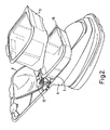
- the lawn mower 1 includes a rigid body 6 around the outside of the lawn mower 1 having an interior edge 7 which defines an opening in the top of the body 6.
- the opening is closed by a lid 8 which is pivotally mounted on the rigid body 6.
- the lid 8 may include a catch by which it is held in the closed position, although no catch is indicated in the drawings.
- the rigid body 6 defines, at least in part, a substantial enclosure within the lawn mower 1.
- the rear wall of the rigid body 6 defines the rear wall of the enclosure, and the front of the enclosure is defined by a wall separating it from the motor 5.
- the lower boundary of the enclosure is defined by the blade housing 2 and by an opening to the impeller 4.
- an inlet 9 opening into the enclosure is positioned so as to face the ground just above the position at which the windrow is left by the cutter blade 3 as the lawn mower 1 is pushed forward.
- Two air permeable grass receptacles 10 and 11, are shaped, firstly so that the outer receptacle 10 will fit within the enclosure such that its air permeable regions are spaced from the walls of the enclosure. The spaces allow air to pass from the air permeable regions through to the eye of the impeller 4 without undue constriction. This will be explained in more detail below.
- the inner receptacle 11 is arranged to fit within the outer receptacle 10 such that it conforms substantially with the interior surface of the outer receptacle 10.
- the inner receptacle I 1 also includes air permeable regions, which in this case, are aligned with the air permeable regions of the outer receptacle 10.
- the inner receptacle 11 is also sized so as to be slightly smaller than the outer receptacle 10 so that it will fit therein.
- the volume within the inner receptacle I 1 for collection of grass cuttings is not substantially less than the volume of the outer receptacle 10 once the inner receptacle 11 is removed.
- the lid 8 can be shut and the lawn mower 1 is ready for use.
- the cutter blade 3 and impeller 4 are caused to rotate at high speed.
- the impeller 4 directs air into the cutting chamber defined by the blade housing 2 whereby the cutting chamber is maintained at a high pressure relative to the ambient pressure. This lifts the lawn mower 1 above the ground (not shown) whereby the air within the cutting chamber escapes beneath the rim of the blade housing 2, which results in hovering of the lawn mower 1 above the ground.
- Rotation of the cutter blade 3 about the vertical axis results in grass being cut, and as the lawn mower 1 is pushed across a lawn, the grass passing beneath the lawn mower is cut by the cutter blade 3 and the grass cuttings are dropped on the ground towards one edge of the lawn mower 1 such that it leaves a windrow of grass cuttings behind it.
- the air directed beneath the blade housing 2 by the impeller 4 is drawn into the lawn mower 1 via the collection inlet 9 at the rear of the machine and into the inner receptacle 11. From there, it is drawn through the air permeable walls of the inner receptacle 11, then through the air permeable walls of the outer receptacle 10 and then through the space between the outer receptacle 10 and the interior walls of the enclosure to the eye of the impeller 4.
- the air drawn into the machine via the collection inlet 9, before entering the machine entrains grass cuttings from the windrow which are carried into the inner receptacle 11.
- the air permeable walls of the receptacles 10, 11 are arranged so as to retain the grass cuttings, and may be in the form of a fabric mesh, or merely slots formed in the walls of the receptacles, or by any other suitable arrangement.
- the inner receptacle 11 will fill up, but the grass cuttings will be compacted by the air passing through the already collected grass cuttings before it reaches the air permeable walls of the receptacles.
- the user can stop the machine, open the lid 8, and lift out the inner receptacle 11, putting it to one side, for instance on the grass that has just been cut, as is shown in Figure 3.
- the lid 8, which is not shown in Figure 3 can then be closed, and the user can continue to mow the lawn until the outer receptacle 10 is filled.
- the outer receptacle 10 Once the outer receptacle 10 has been filled, it to may be lifted out of the lawn mower 1, and as the user carries the outer receptacle 10 full of grass towards the grass disposal point, he can also collect the inner receptacle 11, meaning that a single journey can be made.
- the inner receptacle 11 can be placed on top of the outer receptacle 10 as is shown in Figure 4. Once emptied, the inner receptacle 11 can be nested back within the outer receptacle 10, and the pair of them reinstalled within the body 6 of the lawn mower 1 so that mowing may be continued. Thus the number of journeys that the user has to make to empty the grass is halved. The number of journeys may be further reduced by including more than two receptacles within the body 6.
- the receptacles 10 and 11 could be provided with handles by which the receptacles are supported so that a user can hold one of the receptacles in each hand.
- the present invention is not limited to the embodiment shown in Figures 1-4.
- Various alternatives arrangements which take advantage of the nesting grass receptacle principle are included in this invention.
- the lawn mower 1 shown in Figures 1 and 2 is one supported above the ground by a cushion of air, a hover lawn mower.
- the nesting grass boxes could equally well be applied to a wheel-supported lawn mower, for example.
- the outer receptacle 10 in the embodiment shown is slightly larger than the inner receptacle 11, it would be possible to arrange these to be identical in other embodiments so that it does not matter which receptacle is nested inside the other.
- each of the receptacles 10 and 11 include air permeable regions, the air passing through the air permeable regions on its way to the impeller 4 could experience too much resistance, and so in such arrangements, the air permeable regions inside the inner receptacle 11 might be relatively coarse, whereas the air permeable regions of the outer receptacle 10 might be relatively fine in order to suitably filter the air on its way to the impeller 4. In that case, the outer receptacle 10 would have to be arranged so that it is always in the outermost position with the inner receptacle 11 stacking or nesting within it.
- the receptacles 10 and 11 of the embodiment shown in Figures 1 to 4 are arranged to be mounted in-board, within the rigid body 6 of the lawn mower 1, and above the cutter chamber. However, this could be applied to lawn mowers having the grass collector carried, for example, at the back of the lawn mower attached to the rear of the body of the lawn mower, or hanging from the handle. The inner receptacle 11 would then have to be removable to leave the outer receptacle for grass collection.
- the grass collection arrangement shown in the embodiment of Figures I to 3 is one which collects grass from the ground behind the lawn mower as the lawn mower is pushed forward.
- other arrangements of grass collection exist where the grass cuttings are not dropped on the ground, but directed from the cutting chamber into a receptacle in the air stream generated by the impeller or by upturned vanes at the tips of the cutter blade.
- the present invention may be applied to cutting systems which collect grass other than from the ground.
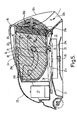
- a lawnmower has a hood or deck 21, and a housing 22 mounted above the deck.
- the deck 21 defines a hover chamber 23 within which an impeller 24 and a cutter blade 25 are rotatably mounted for rotation about a common vertical axis 26.
- the impeller 24 and the cutter blade 25 are powered by an electric motor 27 via a drive belt 28.
- the motor 27 is positioned at the front of the housing 22.
- a grass-box 29 is mounted above the deck 21, the grass-box being formed with cam tracks 30 on its side surfaces.
- the cam tracks 33 cooperate with cams 31 constituted by cylindrical bosses formed inside the side walls of the housing 22 at opposite sides thereof.
- the side walls of the grass-box 29 are formed with perforations 29a, as shown.
- the closed end wall, indicated by the reference 29c, of the grass-box 29 may be formed with perforations in addition to, or instead of, the perforations 29a.
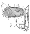
- the grass-box 29 has one end 29b (see in particular Figure 8) which is open over substantially the entire cross-section of the grass-box.
- the cam tracks 30 are aligned with one another, and each has a first, curved portion 30a, and a second, L-shaped portion 30b.
- the free end sections of the L-shaped cam track portions 30b terminate at the closed end wall 29c, of the grass-box 29.
- a lid 32 is pivotally mounted to the housing 22 by means of cylindrical bosses 32 provided on the insides of the side walls of the housing, these bosses engaging within complementary apertures (not shown) formed at the sides of the top, front end (as viewed in Figure 5) of the lid.
- the bosses could extend outwardly from the sides of the lid 32, and engage within complementary apertures formed on the insides of the side walls of the housing.
- bosses 33 constitute cams which engage within cam tracks 34 formed on the side surfaces of the grass-box 29.
- the lid 32 is (as best shown in Figure 8) formed with perforated or grilled portions 32a.
- the lid 32 also defines a collection chute 32b which, in the grass cutting position shown in Figure 5, is downwardly directed towards the ground at the rear of the machine.
- a number of bin liners 35 are positioned inside the grass box 29, with the liners 35 arranged so as to be stacked one inside another. As shown, the free end of the bin liner 35 is wrapped over the rim of the grass-box 29 at the open end 29b thereof.
- FIG. 5 shows the lawnmower in its normal (grass-cutting) position with the grass-box 29 in a generally horizontal position with its open end 29b facing towards the rear of the machine.
- the motor 27 drives the impeller 24 which draws in air (as shown by the arrows B) via the collection chute 32b, the interior of the grass-box 29, and apertures 21 a in the deck 21.
- the air is drawn into the impeller 24 from the interior of the grass-box 29 via the open end 29b, the perforations 32a in the lid 32, and the apertures 21 a.
- the air As the air is drawn in in this manner, it picks up cut grass deposited behind the machine, and carries it into the grass-box 29 where it is deposited. Air then escapes out of the open end 29b of the grass-box 29, and is sucked in by the impeller 24 via the perforated portions 32a of the lid 32 and the apertures 21a.
- the impeller draws air from inside the grass-box 29 through the perforations 29a, to force the bin liner 35 against the internal walls of the grass-box, the air pressure being effective to hold the liner against the internal walls in a fully-open configuration.
- the rear wall 32c of the lid 32 is constituted by a transparent panel, so that the user can see into the machine to see when the grass-box 29 is filling up.
- the grass-box 29 can be removed from the machine by lifting it vertically so that the cams 31 slide along the end sections of the cam track portions 30b.
- the grass-box 29 can then be transported to, for example, a compost heap or to a roadside collection point for emptying. As the grass-box 29 is substantially vertical during this removal process, there is little chance of grass being spilt during the process.
- the grass-box 29 is positioned back into the machine with the end sections of the cam track portions 30b sliding along the cams 31, and with the cams 33 positioned at the ends of the cam tracks 34.
- the lid 32 is then rotated into engagement with the grass-box 29, and subsequently the two members are rotated together until they are in the positions shown in Figure 5.
- the hover mower described above has advantages when compared with known hover mowers.
- the open end of the grass-box 9 is somewhat smaller than the open end of known grass-boxes, and so is much easier to empty into a standard wheelie bin than known grass-boxes.
- cut grass enters the grass-box 29 through the open end 29b (when the grass-box is in the horizontal configuration shown in Figure 5) and is emptied from the same end, there is no need to provide the grass-box with a separate inlet aperture for cut grass, so there is a substantial reduction in the risk of cut grass spilling out when the grass-box is removed from the mower, as this can only be done when the grass-box is substantially vertical.
- the grass-box 9 could be arranged to pivot about a central longitudinal axis of the mower, in which case the grass-box would pivot from side-to-side rather than from front-to-rear as in the embodiment described above. It would also be possible to pivotally mount both the grass-box 29 and the lid 32 by simple pivot means, in which case disengagable interlock members would be provided on the grass-box and on the lid for holding those two members together during the first part of their pivotal movement, that is to say until they rotate from the position shown in Figure 5 to the position shown in Figure 3.
- pre-shaped paper bags may be used instead of using bin liners made of plastics material.
- a single paper bag or a stack of paper bags can be used.
- Such pre-shaped bags may be such as to be storable in a flat configuration.
- the invention which utilises bags within a grass-box could also be used with other lawn care machines such as a scarifier.
- the bags would be positioned one inside another within the debris collector of the scarifier for collecting debris raked from a lawn by the machine.
- the stack of bags positioned with the debris collector will be removed one-by-one as they are filled, in a similar manner to that in which the nested bags are removed from the grass-box of the lawnmower described above.
- the invention is not limited to lawnmower applications, and the term "lawnmower” as used in the claims should be taken to include lawn care machines such as a scarifier. Similarly, the term "cut grass" should be taken to include debris raked from a lawn.
- a nested stack of bags could be used with a garden shredder 41.
- the shredder 41 is provided with an inlet 42 through which garden rubbish such as twigs, plant cuttings etc are fed to a shredding mechanism (not shown) housed within the main body of the shredder.
- a suitable receptacle (not shown) would be fixed to the outlet 43 of the shredder, the receptacle containing a nested stack of bags (also not shown).
- the receptacle In use, once the innermost bag is full, the receptacle would be removed from the shredder 41, the innermost bag together with its shredded contents would be removed, and the receptacle and remaining bags would be fitted back on to the shredder over the outlet 43. The bag which is now the innermost will then be filled with garden debris when the shredder 41 is next used. Once full, the process would be repeated until all the bags are used up.
- a nested stack of bags could be used with a garden vacuum collector of a type used for the picking up leaves and other garden debris.
- the stack of bags would fit over the outlet of the collector, in place of the conventional fabric bag or other form of collector.
- the stack of bags would be removed from the collector, the innermost bag together with its contents would be removed and the remaining bags would be fitted back onto the collector over its outlet.
- a nested stack of bags could be used to collect domestic rubbish bin, for example, a pedal bin or other domestic waste-collection receptacle.
- a stack of nested bags sized to fit a standard pedal bin could be used in place of the usual single bin liner. Once full, the innermost bag and contents would be removed for disposal, leading the remaining bags within the bin. The bin liner now innermost would then be used for rubbish collection and subsequent removal, and the procedure would continue until all the bin liners have been filled.
Landscapes
- Life Sciences & Earth Sciences (AREA)
- Environmental Sciences (AREA)
- Harvester Elements (AREA)
- Connection Of Batteries Or Terminals (AREA)
Applications Claiming Priority (4)
| Application Number | Priority Date | Filing Date | Title |
|---|---|---|---|
| GB0224210A GB2394159A (en) | 2002-10-17 | 2002-10-17 | Nesting grass collector receptacles |
| GB0224210 | 2002-10-17 | ||
| GB0228401A GB2394160A (en) | 2002-10-17 | 2002-12-05 | Nesting grass collector receptacles |
| GB0228401 | 2002-12-05 |
Publications (3)
| Publication Number | Publication Date |
|---|---|
| EP1410708A2 true EP1410708A2 (fr) | 2004-04-21 |
| EP1410708A3 EP1410708A3 (fr) | 2004-12-22 |
| EP1410708B1 EP1410708B1 (fr) | 2008-10-08 |
Family
ID=32044471
Family Applications (1)
| Application Number | Title | Priority Date | Filing Date |
|---|---|---|---|
| EP20030254900 Expired - Lifetime EP1410708B1 (fr) | 2002-10-17 | 2003-08-06 | Collecteur d'herbe |
Country Status (1)
| Country | Link |
|---|---|
| EP (1) | EP1410708B1 (fr) |
Cited By (5)
| Publication number | Priority date | Publication date | Assignee | Title |
|---|---|---|---|---|
| GB2429623A (en) * | 2005-08-31 | 2007-03-07 | Husqvarna Uk Ltd | Lawnmower having grass collection box |
| WO2010108511A1 (fr) * | 2009-03-26 | 2010-09-30 | Husqvarna Uk Ltd. | Tondeuses à gazon |
| US20210112710A1 (en) * | 2019-10-18 | 2021-04-22 | Bluebird Turf Products LLLP, A Delaware Limited Liability Partnership | Electric Power Hover Lawn Mower |
| CN115669359A (zh) * | 2022-09-27 | 2023-02-03 | 浙江亚特电器股份有限公司 | 一种割草机启停控制机构、控制方法及割草机 |
| DE102020207031B4 (de) * | 2019-07-02 | 2024-03-14 | Honda Motor Co., Ltd. | Rasenmäher |
Family Cites Families (13)
| Publication number | Priority date | Publication date | Assignee | Title |
|---|---|---|---|---|
| DE1582482A1 (de) * | 1966-12-06 | 1970-06-11 | Wolf Elmar Joseph | Anordnung mit Grasfangkorb und Transportgestell fuer Rasenmaeher |
| GB1247057A (en) * | 1968-10-10 | 1971-09-22 | Richard Franklin Nestler | Packaging with plastics bags |
| US3641754A (en) * | 1970-07-22 | 1972-02-15 | Sperry Rand Corp | Grass and leaf packaging machine |
| US3736736A (en) * | 1972-03-06 | 1973-06-05 | Deere & Co | Baling attachment for lawn mowers |
| US4119414A (en) * | 1976-12-15 | 1978-10-10 | National Union Electric Corporation | Filter bag construction for a vacuum cleaner and method of operation |
| FR2437154A1 (fr) * | 1978-09-28 | 1980-04-25 | Wolf Outils | Dispositif de reception de l'herbe coupee par une tondeuse a gazon |
| US4566257A (en) * | 1984-06-29 | 1986-01-28 | Mohammad Akrabawi | Lawn mower disposable grass collection bag attachment |
| US4747259A (en) * | 1986-10-01 | 1988-05-31 | Kline Daniel J | Grass catching assembly and disposable bag therefor |
| US4907403A (en) * | 1989-02-06 | 1990-03-13 | Otis Jones | Grass mower improvement |
| US5042241A (en) * | 1989-09-01 | 1991-08-27 | Fuqua Industries, (Snapper Division) | Grass catcher assembly and method |
| GB9008569D0 (en) * | 1990-04-17 | 1990-06-13 | Electrolux Northern | Lawn mowers |
| US5564265A (en) * | 1994-02-28 | 1996-10-15 | Pitt; Leo | Grass catcher insert and adapter for lawn mowers |
| US5522908A (en) * | 1994-05-27 | 1996-06-04 | Hmi Industries, Inc. | Filter bag for a vacuum cleaner |
-
2003
- 2003-08-06 EP EP20030254900 patent/EP1410708B1/fr not_active Expired - Lifetime
Cited By (7)
| Publication number | Priority date | Publication date | Assignee | Title |
|---|---|---|---|---|
| GB2429623A (en) * | 2005-08-31 | 2007-03-07 | Husqvarna Uk Ltd | Lawnmower having grass collection box |
| EP1759575A3 (fr) * | 2005-08-31 | 2007-10-17 | Husqvarna UK Limited | Tondeuse à gazon |
| GB2429623B (en) * | 2005-08-31 | 2008-04-09 | Husqvarna Uk Ltd | Lawnmower |
| WO2010108511A1 (fr) * | 2009-03-26 | 2010-09-30 | Husqvarna Uk Ltd. | Tondeuses à gazon |
| DE102020207031B4 (de) * | 2019-07-02 | 2024-03-14 | Honda Motor Co., Ltd. | Rasenmäher |
| US20210112710A1 (en) * | 2019-10-18 | 2021-04-22 | Bluebird Turf Products LLLP, A Delaware Limited Liability Partnership | Electric Power Hover Lawn Mower |
| CN115669359A (zh) * | 2022-09-27 | 2023-02-03 | 浙江亚特电器股份有限公司 | 一种割草机启停控制机构、控制方法及割草机 |
Also Published As
| Publication number | Publication date |
|---|---|
| EP1410708B1 (fr) | 2008-10-08 |
| EP1410708A3 (fr) | 2004-12-22 |
Similar Documents
| Publication | Publication Date | Title |
|---|---|---|
| US3971198A (en) | Collector for a power lawnmower | |
| US3974631A (en) | Grass catcher assembly | |
| US7354466B2 (en) | Collector and separator apparatus for lawn and garden | |
| US5117616A (en) | Mulching lawn mower | |
| US7806593B2 (en) | Refuse bag with improved air removal and content compaction | |
| US4522019A (en) | Grass catching receptacle | |
| JPH04271718A (ja) | 芝刈り機 | |
| US6966169B2 (en) | Mowing machine chute cleaner apparatuses and methods | |
| US20060277714A1 (en) | Collector and separator apparatus for lawn and garden | |
| US3877207A (en) | Appliance | |
| US4986062A (en) | Bagger attachment for grass mowers | |
| US4411125A (en) | Multi-function apparatus for lawn maintenance | |
| EP1410708A2 (fr) | Collecteur d'herbe | |
| GB2261585A (en) | Cut grass collection system. | |
| US10959375B1 (en) | Refuse catcher bag for a ground tending machine | |
| EP0610062A1 (fr) | Dispositif collecteur | |
| US7736422B2 (en) | Cyclonic separation grassbag apparatuses and methods for mowing machines | |
| EP1425955A2 (fr) | Tondeuse à gazon | |
| GB2394160A (en) | Nesting grass collector receptacles | |
| CN103843520B (zh) | 布置为收集草地碎屑的草地真空设备 | |
| US20060144030A1 (en) | Machine for removing vegetation | |
| EP1419686B1 (fr) | Tondeuse à gazon | |
| EP1759575A2 (fr) | Tondeuse à gazon | |
| WO2007017658A1 (fr) | Tondeuse a gazon | |
| GB2400297A (en) | Machine for removing vegetation |
Legal Events
| Date | Code | Title | Description |
|---|---|---|---|
| PUAI | Public reference made under article 153(3) epc to a published international application that has entered the european phase |
Free format text: ORIGINAL CODE: 0009012 |
|
| AK | Designated contracting states |
Kind code of ref document: A2 Designated state(s): AT BE BG CH CY CZ DE DK EE ES FI FR GB GR HU IE IT LI LU MC NL PT RO SE SI SK TR |
|
| AX | Request for extension of the european patent |
Extension state: AL LT LV MK |
|
| RIC1 | Information provided on ipc code assigned before grant |
Ipc: 7A 47L 9/14 B Ipc: 7A 01D 43/063 B Ipc: 7A 01D 43/06 A |
|
| PUAL | Search report despatched |
Free format text: ORIGINAL CODE: 0009013 |
|
| AK | Designated contracting states |
Kind code of ref document: A3 Designated state(s): AT BE BG CH CY CZ DE DK EE ES FI FR GB GR HU IE IT LI LU MC NL PT RO SE SI SK TR |
|
| AX | Request for extension of the european patent |
Extension state: AL LT LV MK |
|
| 17P | Request for examination filed |
Effective date: 20050304 |
|
| 17Q | First examination report despatched |
Effective date: 20050503 |
|
| AKX | Designation fees paid |
Designated state(s): DE FR GB |
|
| RAP1 | Party data changed (applicant data changed or rights of an application transferred) |
Owner name: HUSQVARNA UK LIMITED |
|
| GRAP | Despatch of communication of intention to grant a patent |
Free format text: ORIGINAL CODE: EPIDOSNIGR1 |
|
| GRAS | Grant fee paid |
Free format text: ORIGINAL CODE: EPIDOSNIGR3 |
|
| GRAA | (expected) grant |
Free format text: ORIGINAL CODE: 0009210 |
|
| AK | Designated contracting states |
Kind code of ref document: B1 Designated state(s): DE FR GB |
|
| REG | Reference to a national code |
Ref country code: GB Ref legal event code: FG4D |
|
| REF | Corresponds to: |
Ref document number: 60323918 Country of ref document: DE Date of ref document: 20081120 Kind code of ref document: P |
|
| PLBE | No opposition filed within time limit |
Free format text: ORIGINAL CODE: 0009261 |
|
| STAA | Information on the status of an ep patent application or granted ep patent |
Free format text: STATUS: NO OPPOSITION FILED WITHIN TIME LIMIT |
|
| PGFP | Annual fee paid to national office [announced via postgrant information from national office to epo] |
Ref country code: FR Payment date: 20090612 Year of fee payment: 7 |
|
| 26N | No opposition filed |
Effective date: 20090709 |
|
| PGFP | Annual fee paid to national office [announced via postgrant information from national office to epo] |
Ref country code: GB Payment date: 20090611 Year of fee payment: 7 Ref country code: DE Payment date: 20090616 Year of fee payment: 7 |
|
| GBPC | Gb: european patent ceased through non-payment of renewal fee |
Effective date: 20100806 |
|
| REG | Reference to a national code |
Ref country code: FR Ref legal event code: ST Effective date: 20110502 |
|
| REG | Reference to a national code |
Ref country code: DE Ref legal event code: R119 Ref document number: 60323918 Country of ref document: DE Effective date: 20110301 |
|
| PG25 | Lapsed in a contracting state [announced via postgrant information from national office to epo] |
Ref country code: DE Free format text: LAPSE BECAUSE OF NON-PAYMENT OF DUE FEES Effective date: 20110301 Ref country code: FR Free format text: LAPSE BECAUSE OF NON-PAYMENT OF DUE FEES Effective date: 20100831 |
|
| PG25 | Lapsed in a contracting state [announced via postgrant information from national office to epo] |
Ref country code: GB Free format text: LAPSE BECAUSE OF NON-PAYMENT OF DUE FEES Effective date: 20100806 |