EP1410859B1 - Randbearbeitungs-/gummiervorrichtung für nicht runde metallische deckel für behälter - Google Patents
Randbearbeitungs-/gummiervorrichtung für nicht runde metallische deckel für behälter Download PDFInfo
- Publication number
- EP1410859B1 EP1410859B1 EP02727614A EP02727614A EP1410859B1 EP 1410859 B1 EP1410859 B1 EP 1410859B1 EP 02727614 A EP02727614 A EP 02727614A EP 02727614 A EP02727614 A EP 02727614A EP 1410859 B1 EP1410859 B1 EP 1410859B1
- Authority
- EP
- European Patent Office
- Prior art keywords
- lid
- curling
- sealing compound
- compound lining
- containers
- Prior art date
- Legal status (The legal status is an assumption and is not a legal conclusion. Google has not performed a legal analysis and makes no representation as to the accuracy of the status listed.)
- Expired - Lifetime
Links
Images


Classifications
-
- B—PERFORMING OPERATIONS; TRANSPORTING
- B05—SPRAYING OR ATOMISING IN GENERAL; APPLYING FLUENT MATERIALS TO SURFACES, IN GENERAL
- B05C—APPARATUS FOR APPLYING FLUENT MATERIALS TO SURFACES, IN GENERAL
- B05C5/00—Apparatus in which liquid or other fluent material is projected, poured or allowed to flow on to the surface of the work
- B05C5/02—Apparatus in which liquid or other fluent material is projected, poured or allowed to flow on to the surface of the work the liquid or other fluent material being discharged through an outlet orifice by pressure, e.g. from an outlet device in contact or almost in contact, with the work
- B05C5/0208—Apparatus in which liquid or other fluent material is projected, poured or allowed to flow on to the surface of the work the liquid or other fluent material being discharged through an outlet orifice by pressure, e.g. from an outlet device in contact or almost in contact, with the work for applying liquid or other fluent material to separate articles
- B05C5/0212—Apparatus in which liquid or other fluent material is projected, poured or allowed to flow on to the surface of the work the liquid or other fluent material being discharged through an outlet orifice by pressure, e.g. from an outlet device in contact or almost in contact, with the work for applying liquid or other fluent material to separate articles only at particular parts of the articles
- B05C5/0216—Apparatus in which liquid or other fluent material is projected, poured or allowed to flow on to the surface of the work the liquid or other fluent material being discharged through an outlet orifice by pressure, e.g. from an outlet device in contact or almost in contact, with the work for applying liquid or other fluent material to separate articles only at particular parts of the articles by relative movement of article and outlet according to a predetermined path
- B05C5/022—Apparatus in which liquid or other fluent material is projected, poured or allowed to flow on to the surface of the work the liquid or other fluent material being discharged through an outlet orifice by pressure, e.g. from an outlet device in contact or almost in contact, with the work for applying liquid or other fluent material to separate articles only at particular parts of the articles by relative movement of article and outlet according to a predetermined path the outlet being fixed during operation
-
- B—PERFORMING OPERATIONS; TRANSPORTING
- B05—SPRAYING OR ATOMISING IN GENERAL; APPLYING FLUENT MATERIALS TO SURFACES, IN GENERAL
- B05C—APPARATUS FOR APPLYING FLUENT MATERIALS TO SURFACES, IN GENERAL
- B05C5/00—Apparatus in which liquid or other fluent material is projected, poured or allowed to flow on to the surface of the work
- B05C5/02—Apparatus in which liquid or other fluent material is projected, poured or allowed to flow on to the surface of the work the liquid or other fluent material being discharged through an outlet orifice by pressure, e.g. from an outlet device in contact or almost in contact, with the work
- B05C5/0208—Apparatus in which liquid or other fluent material is projected, poured or allowed to flow on to the surface of the work the liquid or other fluent material being discharged through an outlet orifice by pressure, e.g. from an outlet device in contact or almost in contact, with the work for applying liquid or other fluent material to separate articles
- B05C5/0212—Apparatus in which liquid or other fluent material is projected, poured or allowed to flow on to the surface of the work the liquid or other fluent material being discharged through an outlet orifice by pressure, e.g. from an outlet device in contact or almost in contact, with the work for applying liquid or other fluent material to separate articles only at particular parts of the articles
- B05C5/0216—Apparatus in which liquid or other fluent material is projected, poured or allowed to flow on to the surface of the work the liquid or other fluent material being discharged through an outlet orifice by pressure, e.g. from an outlet device in contact or almost in contact, with the work for applying liquid or other fluent material to separate articles only at particular parts of the articles by relative movement of article and outlet according to a predetermined path
-
- B—PERFORMING OPERATIONS; TRANSPORTING
- B05—SPRAYING OR ATOMISING IN GENERAL; APPLYING FLUENT MATERIALS TO SURFACES, IN GENERAL
- B05B—SPRAYING APPARATUS; ATOMISING APPARATUS; NOZZLES
- B05B13/00—Machines or plants for applying liquids or other fluent materials to surfaces of objects or other work by spraying, not covered by groups B05B1/00 - B05B11/00
- B05B13/02—Means for supporting work; Arrangement or mounting of spray heads; Adaptation or arrangement of means for feeding work
- B05B13/0221—Means for supporting work; Arrangement or mounting of spray heads; Adaptation or arrangement of means for feeding work characterised by the means for moving or conveying the objects or other work, e.g. conveyor belts
- B05B13/0242—Means for supporting work; Arrangement or mounting of spray heads; Adaptation or arrangement of means for feeding work characterised by the means for moving or conveying the objects or other work, e.g. conveyor belts the objects being individually presented to the spray heads by a rotating element, e.g. turntable
-
- B—PERFORMING OPERATIONS; TRANSPORTING
- B05—SPRAYING OR ATOMISING IN GENERAL; APPLYING FLUENT MATERIALS TO SURFACES, IN GENERAL
- B05C—APPARATUS FOR APPLYING FLUENT MATERIALS TO SURFACES, IN GENERAL
- B05C11/00—Component parts, details or accessories not specifically provided for in groups B05C1/00 - B05C9/00
- B05C11/02—Apparatus for spreading or distributing liquids or other fluent materials already applied to a surface ; Controlling means therefor; Control of the thickness of a coating by spreading or distributing liquids or other fluent materials already applied to the coated surface
- B05C11/08—Spreading liquid or other fluent material by manipulating the work, e.g. tilting
-
- Y—GENERAL TAGGING OF NEW TECHNOLOGICAL DEVELOPMENTS; GENERAL TAGGING OF CROSS-SECTIONAL TECHNOLOGIES SPANNING OVER SEVERAL SECTIONS OF THE IPC; TECHNICAL SUBJECTS COVERED BY FORMER USPC CROSS-REFERENCE ART COLLECTIONS [XRACs] AND DIGESTS
- Y10—TECHNICAL SUBJECTS COVERED BY FORMER USPC
- Y10T—TECHNICAL SUBJECTS COVERED BY FORMER US CLASSIFICATION
- Y10T29/00—Metal working
- Y10T29/53—Means to assemble or disassemble
- Y10T29/53313—Means to interrelatedly feed plural work parts from plural sources without manual intervention
- Y10T29/53374—Means to interrelatedly feed plural work parts from plural sources without manual intervention including turret-type conveyor
-
- Y—GENERAL TAGGING OF NEW TECHNOLOGICAL DEVELOPMENTS; GENERAL TAGGING OF CROSS-SECTIONAL TECHNOLOGIES SPANNING OVER SEVERAL SECTIONS OF THE IPC; TECHNICAL SUBJECTS COVERED BY FORMER USPC CROSS-REFERENCE ART COLLECTIONS [XRACs] AND DIGESTS
- Y10—TECHNICAL SUBJECTS COVERED BY FORMER USPC
- Y10T—TECHNICAL SUBJECTS COVERED BY FORMER US CLASSIFICATION
- Y10T29/00—Metal working
- Y10T29/53—Means to assemble or disassemble
- Y10T29/534—Multiple station assembly or disassembly apparatus
- Y10T29/53404—Multiple station assembly or disassembly apparatus including turret-type conveyor
Definitions
- the present invention relates to a curling - sealing compound lining machine for non-circular metal lids of containers, from among the various machines intended for this type of construction of said container components, whether these are bases or lids of any non-circular shape, in rectangular, oval, square, triangular and other configurations (See for example US-A-5 997 648 ).
- This invention is characterised by a special construction of the machine that allows a simultaneous curling and sealing compound lining of the lid, improving its finish, increasing production and facilitating access of the lids to the sealing compound-drying oven, all of this by a rotary construction of the machine, with several consecutive, complementary working positions for the curling devices and the sealing compound lining devices, that are movable and opposite each other in every position.
- Feeding is performed continuously, that is, without any stoppages of the main platen, as well as improving the deposition of the lid, which is carried out in the core gradually and without errors.
- the discharge is also continuous and synchronised, by simultaneously providing two different speeds for the lid-conveying means.
- the machine allows a simple exchange of the lid-carrying plates, the copying cam, when the implementation is by a mechanical cam, while when using an electronic cam it is enough to reprogram the servomotor set, naturally replacing the down-stacker with another suitable for the new configuration, all of this enabling a simple adaptation to any lid shape.
- roller curlers which generally used two complementary curling rollers with an incomplete finishing that resulted in a complicated closure of the container. These curling defects also cause a sealing compound fillet in a critical position, as the sealing compound wets the corners more than would be desirable.
- sealing compound lining machines tampon systems are known that use a sealing compound arc with a capacity on the order of 100 lids/min. that cannot provide sealing compound to the lid flange. Equally imperfect is sealing compound showering, also using a non-revolving method, in which a mask leaves open a projection of a multiplicity of small sealing compound droplets that together form a set of aligned points that replaces the sealing compound band, naturally also used for central application of sealing compound and not under the lid curl, although it is three times faster than the immediately preceding system.
- a lid is deposited during the stop of the belt and another during its motion, with these lids being sent to corresponding sealing compound lining stations.
- the lid rotates about its axis and the sealing compound, provided with servomechanisms that can only make it rotate about its vertical axis, applies the sealing compound in different angles of inclination resulting in a sealing compound lining band that does not maintain its distance from the lid edge, despite the cost of installing the electronic control servomechanisms for the guns;
- the type of lid to which the sealing compound lining is applied cannot be changed as it can only be positioned by gravity, the lids are not discharged with accurate regularity, and the machine cannot operate with any conventional drying oven, nor with two independent ovens or with an oven having two scoop towers.
- lid-feeding device in the cases described heretofore, with the exception of the aforementioned double feeding system, this is performed with the belt or the rotary base stopped, and under gravity.
- One known system involves a lid held in a lower, displaceable base provided with an orifice to allow the lid to fall, together with jack-knife clips that hold the pile of remaining lids placed on top of the lowermost one, until the platform returns and the clips let the lids fall on the un-perforated area of said platform.
- worm gear with generally two opposite ones used that feed each lid to a lower platen provided with satellite platens in charge of feeding the lid tangentially and with the lid support stopped.
- the present invention provides a curling-sealing compound lining machine according to claim 1.
- the present invention relates to a curling - sealing compound lining machine for non-circular container lids from among the various machines intended for this type of construction of the said components of containers, whether they are bases or lids of any non-circular shape.
- a machine comprised of a single unit, with a prismatic construction and a body provided with common driving means, as well as an upper base having a rotary platen, that performs both the curling and sealing compound lining operations simultaneously at a high speed, rotating the lid and attaining productions of 800 lids/min.
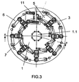
- the platen has a number of different working positions or stations that are equidistant and have a complementary consecutive action, both for the curling and the sealing compound lining devices. Both types of device are set opposite each other in each workstation, and are movable such that along a theoretical arc of almost 90° that matches the closest position of said curling and sealing compound lining devices, both the curling and sealing compound lining means are distanced from their usual working positions.
- the lid does not rotate about its axis; however, if the number of stations were changed if the machine were gradually increased or reduced in size or if the distance between said workstations were changed, it may be that the lid would rotate a fraction of a revolution in the first station, in the last or in both.
- the three remaining theoretical 90° arcs are used for performing at most three full revolutions of the lid, so that all are used for curling and only two at most for sealing compound lining, remarking that during sealing compound lining a slight sealing compound overlapping is recommendable between the sealing compound lining end point of the first revolution and the sealing compound lining end point of the process, which leads to a slight increase in the run of the gun.
- This difference of action of the two devices implies a separation between the curling and sealing compound lining operations to serve as a cushion between the initial and final parts of this theoretical case, i.e. between the central, preferably sealing compound lining, arc of somewhat more than 180° when including the sealing compound overlap, and the maximum revolutions curling arc of about 270°, equivalent to three curling revolutions, with the last revolution preferably used for fine adjustment of the lid edge.
- the lid-carrying platen does not turn about its axis to facilitate feeding and discharge of the lid; it is possible to reduce said theoretical or to increase the number of devices for discharge or feeding.
- the construction of the sealing compound lining device allows a completely accurate inclination of the gun in any desired angle on the plane internally tangent to the edge of the lid flange, so that the width of the sealing compound stream allows to focus it not only on the inside face of the lid but also on the inner segment of the flange rounding, and by centrifugal force to a considerable extent of the flange, this being a clear advantage over the gun balancing system that in an extreme position brings the sealing compound unnecessarily close to the same edge and, alternatively, at the opposite extreme position displaces the sealing compound towards the inside of the lid, where it is not useful.
- the final closure of the container is also facilitated by a later fine adjustment of the edge line of the lid or the base in its last turn in the core.
- the new feeding device allows feeding to be performed continuously for all lids, without any stoppages, improving the depositing of the lid on the lid-bearing platen, which is performed gradually and without errors by first resting a long side of the lid on the protrusion of the lid bearing core, while the worm gear maintains the lid held on the opposite side and lets it enter this protrusion gradually by pulling on the edges of the core until the lid is fully inserted in the core, with the aid in the case of ferromagnetic lids of the magnetic field created inside the core, or alternatively, of the suction force exerted by conventional vacuum means in the case of aluminium and other non-ferromagnetic lids.
- a top ring can be provided to guide the top central part of the lid. This ring will have a break in the lid discharge and feed area.
- the curling arm will approach, followed by the sealing compound lining arm, which had both retracted previously to discharge the lid, which lid has in turn completed the full revolution of 360° for curling and sealing compound lining in the machine.
- the arms are also retracted to prevent collisions with the feed tower.
- the discharge device allows a synchronised exit of the lids and bases by having a conveyor belt provided with either a magnetic element of greater strength than that of the core, or a lid suction power greater than that of the vacuum that held it to the core, or a combination of the two depending on each case.
- the lid falls on a miniature conveying system with two different speeds, with the belt speed faster than the synchronism chain speed.
- the latter has flanges so that when acting simultaneously they allow a continuous and synchronised conveying of the lids to the drying oven.
- this machine in addition to curling and sealing compound lining simultaneously allows operating with any type of lid shape by simply resorting to an easy and quick exchange of the down-stacker, the lid-bearing platens and the copying cam, in the simplest and cheapest case of using a mechanical cam, while in the alternative case of using an electronic cam, when the user wishes to do so for whichever reason, such as when launching short series of different lid formats and wishing to minimise the time of replacing components, no mechanical device need be replaced as it is sufficient to reprogram the servomotors, allowing a simple adaptation to all lid shapes.
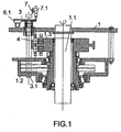
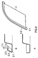
- the present invention relates to a curling - sealing compound lining machine for non-circular container lids characterised by being comprised of a single unit, with a prismatic construction and a body provided with common driving means, as well as an upper base having a rotary platen (1), that in addition to performing both the curling and sealing compound lining operations simultaneously and at a high speed, allows operation with any type of profile of the lid (2) or base, adapting to any shape of these, for which is performed a simple and quick exchange of the lid-carrying platens (3), the copying cam (1.2) and the down-stacker (8.1); the machine (4) operates by rotating the lids among a number of workstations (5), preferably equidistant, provided with curling (6) and sealing compound lining (7) devices that are placed diametrically opposite each other in each station and are capable of moving from their usual working positions along an arc that matches the consecutive location of the feeding (8) and discharge (9) devices.
- the lid (2) does not revolve at all, while in the arc remaining to complete the circle or to reach the following area of location of further feeding (8) and discharge (9) devices the lid (2) turns one or more full revolutions in each station (5) for curling and sealing compound lining, with the latter process preferably including a small overlap (10.1) of the continuous sealing compound band (10).
- the revolution-free arc of the lid-carrier is a 90° arc, with three full revolutions performed in the following 270°, in which already act the corresponding curling (6) and sealing compound lining (7) devices that act in this single set of devices, completing the operation with the lid (2).
- the curling device (6) is provided with a curling roller (6.1) held by a rod (11) and attached to a follower arm (12) that follows the path of the bottom face (1.3.1) of the copying cam (1.3), with the cams remaining fixed in place and with the assembly formed by the platen (1) and the supporting arm (1.2) of the shafts (3.1) turning about it.
- Said support arm (1.2) of the shafts (3.1) is in charge of providing the rotation of the lid-carrying platen (3) about its shaft (3.1) by a conventional cam-follower system.
- the sealing compound lining device (7) inclines the gun (7.1) with full accuracy, following the upper profile (1.3.2) of the copying cam (1.3) by means of the follower arm (13) in any angle desired with respect to the plane of attachment to the arm (7.2) set for each type of lid, and focusing the sealing compound stream (7.3) to the base (2.1) of the lid (2), and by centrifugal force to the inner face of the flange (2.2) and to a considerable extent of the inner rounded segment (2.3) of said face, as the curling precedes the sealing compound lining and there is no external overflow whatsoever of the sealing compound, with the final closure of the lid favoured by the fine adjustment of the edge line of the lid (2).
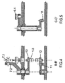
- the feeding device (8) is provided with a single spindle (8.1) and deposits continuously the lids (2) without stops or errors, first holding a long side (2.1) of the bottom lid (2) of the lid deposit (8.2) in the core (3.1) of the lid carrier (3) and then gradually resting it on the core protrusion (3.1), with the lid held by the worm gear (8.1) and on its opposite side (2.2) by the deposit (8.2), which is suitably inclined for this purpose and also to facilitate the introduction of the spindle through the end of its uppermost base (8.2.1) until it is fully inserted in the core (3.1), in which operation participate, either alternatively or complementarily, magnets (3.2) inserted in the core (3.1) or conventional vacuum means.
- the curling device (6) approaches first, and after it the sealing compound lining device (7), which had been retracted earlier by the discharge device (9) of the last finished lid (2) in order to free space for passage of the feeding tower (8.2).
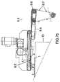
- the discharge device (9) is provided with a conveyor belt (9.1) having a magnetic element (9.2), that is more powerful than the magnets (3.2) of the core (3.1), and/or vacuum means that are stronger than the vacuum used to hold the lid (2) in its circular path, such that latter may remain or be eliminated when not required, then stopping the action of either of the means for absorbing the lid (2), which will fall on a mini-conveyor (9.3) provided with a belt (9.4) and a synchronism chain (9.5) that move at different speeds as they are arranged with different diameters of the main pinion (9.6), with that of the belt (9.4) greater than that of the chain (9.5), and the latter having flanges (9.7) for holding the extracted lid (2), synchronising the continuous conveying of the lids (2) to the drying oven.
- a conveyor belt (9.1) having a magnetic element (9.2), that is more powerful than the magnets (3.2) of the core (3.1), and/or vacuum means that are stronger than the vacuum used to hold the lid (2) in its
- top guide ring for the upper central part of the lid (2) that will be open at the segment of the platen (1) located between lid discharge and feeding.
- the machine (4) may incorporate different numbers of workstations (5) in either odd or even numbers if, in order to optimise the ratio between the revolutions of the platen (1) and the revolutions of the lid-carrying platens (3) it is preferable to have machines with 4, 6, 8, 10 or 12 workstations (5), although greater numbers are not advisable as the size of the machine would interfere with the production line.
- an equal number of revolution-free arcs of the lid carrier (3) are installed with a coverage angle appropriate for the stations (5), so that the two are separated and arranged according to the corresponding revolution sector, while the curling and sealing compound lining devices (6) and (7) that operate with each set of arcs complete their action with the lid (2) before arriving at the following arc, that begins at the location of the new discharge device (9) of the curled and sealing-compound lined lid (2) and ends at the feeding device (8) that initiates the following operation on the lid (2).
- the feeding and discharge devices (8) and (9) can be arranged in double sets, so that a set of feeding and discharge devices (8) and (9) acts with even positions of the stations (5) and another set accts with the odd positions.
- These odd or even positions can incorporate lids (2) that are identical or different from each other.
- the curling and sealing compound lining operations in the corresponding arc and with the appropriate number of revolutions, depending on the curling and sealing compound lining arcs and the stoppage arcs, as designed for each case, can be effected by a specific design of the copying cam (1.3) and the support arm (1.2) of the shafts (3.1) or, when implementing an electronic cam, by reprogramming the servomotor assembly.
Landscapes
- Closing Of Containers (AREA)
- Sealing Of Jars (AREA)
- Processing And Handling Of Plastics And Other Materials For Molding In General (AREA)
- Heating, Cooling, Or Curing Plastics Or The Like In General (AREA)
- Shaping Of Tube Ends By Bending Or Straightening (AREA)
- Containers Having Bodies Formed In One Piece (AREA)
- Confectionery (AREA)
Claims (18)
- Randbearbeitungs-/Gummiervorrichtung für nicht runde metallische Deckel für Behälter, gekennzeichnet durch einen ununterbrochenen Betrieb und dadurch, dass sie in einem einzigen Körper mit einer prismatischen Konstruktion und einem Körper, der Folgendes umfasst, enthalten ist:- eine obere Basis, die eine große drehbare Auflageplatte (1) einschließt;- eine Anzahl von Workstations (5), vorzugsweise äquidistant voneinander, angebracht auf der Auflageplatte (1) und ausgestattet mit Randbearbeitungs- (6) und Gummivorrichtungen (7), die einander diametral gegenüber in jeder Station (5) angebracht sind;- ein oder mehrere Sätze von Zuführvorrichtungen (8) und Abgabevorrichtungen (9), die nacheinander in der angemessenen Reihenfolge auf der Auflageplatte (1) angebracht sind;- gemeinsame Betätigungsmittel für diese Stationen (5) innerhalb der Vorrichtung (4);so dass:- die drehbare Auflageplatte (1) außer, dass sie sowohl den Randbearbeitungs- als auch den Gummierungsbetrieb ununterbrochen und mit hoher Geschwindigkeit durchführt, ein Arbeiten mit jeder Art von Profil des Deckels (2) oder der Basis, eine Anpassung an jede Form durch Drehen der Deckel (2) in den Workstations (5) ermöglicht;- die Randbearbeitungs- (6) und Gummierungsvorrichtungen (7) sich aus ihren gewöhnlichen Arbeitspositionen entlang des Bogens bewegen können, auf dem die Zuführungs- (8) und Abgabevorrichtungen (9) angebracht sind, die ebenfalls ununterbrochen arbeiten.
- Randbearbeitungs-/Gummiervorrichtung für nicht runde metallische Deckel für Behälter nach Anspruch 1, dadurch gekennzeichnet, dass auf dem Bogen der drehbaren Auflageplatte (1), besetzt durch den einzelnen Satz von Zuführungs- (8) und Abgabevorrichtungen (9), keine Drehung des Deckels (2) stattfindet, während auf dem Bogen, der verbleibt, um den Kreis zu vervollständigen, eine oder mehrere vollständige Drehungen des Deckels (2) in jeder Station (5) zur Randbearbeitung und Gummierung stattfinden, wobei letzterer Betrieb vorzugsweise eine kleine Überlappung (10.1) des ununterbrochenen Gummierbandes (10) umfasst.
- Randbearbeitungs-/Gummiervorrichtung für nicht runde metallische Deckel für Behälter nach Anspruch 1 oder 2, dadurch gekennzeichnet, dass in diesem einzelnen Satz von Zuführungs- (8) und Abgabevorrichtungen (9) der drehungsfreie Bogen des Deckelträgers ein 90°-Bogen ist, wobei drei vollständige Drehungen auf den folgenden 270° durchgeführt werden, in denen die entsprechenden Randbearbeitungs- (6) und Gummiervorrichtungen (8) bereits in Betrieb sind.
- Randbearbeitungs-/-Gummiervorrichtung für nicht runde metallische Deckel für Behälter nach einem der Ansprüche 1 bis 3, dadurch gekennzeichnet, dass während dieser Drehungen zwei Randbearbeitungs- und Gummiervorgänge stattfinden, die praktisch simultan erfolgen, obwohl ersterer geringfügig früher stattfindet, wobei die dritte Drehung, die für die Randbearbeitungsvorrichtung (6) durchgeführt wird, für eine Feineinstellung oder Kalibrierung der Randes (2.3) des Flansches (2.2) des Endabschnittes (2.1) des Deckels (2) vorgesehen ist.
- Randbearbeitungs-/Gummiervorrichtung für nicht runde metallische Deckel für Behälter nach Anspruch 3 oder 4, dadurch gekennzeichnet, dass die Drehungen des Deckelträgers (3) auf seinem entsprechenden Bogen durch ganze Zahlen variiert werden können und mit ihnen die Vorgänge der Randbearbeitungs- (6) und Gummiervorrichtungen (7).
- Randbearbeitungs-/Gummiervorrichtung für nicht runde metallische Deckel für Behälter nach einem der Ansprüche 3 bis 5, dadurch gekennzeichnet, dass die Anzahl von Vorgängen der Randbearbeitungs- (6) und Gummiervorrichtungen (7) in jedem entsprechenden Bogen identisch ist.
- Randbearbeitungs-/Gummiervorrichtung für nicht runde metallische Deckel für Behälter nach Anspruch 1 oder 2, dadurch gekennzeichnet dass, wenn mehr als ein Satz von Zuführungs- (8) und Abgabevorrichtungen (9) bereitgestellt wird, diese gemäß dem entsprechenden Drehsektor getrennt und angeordnet werden, während die Randbearbeitungs- (6) und Gummiervorrichtungen (7), die mit jedem Satz der oben angegebenen Vorrichtungen in Betrieb sind, ihre Wirkung auf den Deckel (2) vervollständigen, bevor sie den folgenden Bogen erreichen, der am Standort der neuen Abgabevorrichtung (9) des randbearbeiteten und gummierten Deckels (2) beginnt und an der entsprechenden Zuführungsvorrichtung (8) endet, die den Beginn des folgenden Vorgangs auf dem Deckel (2) signalisiert.
- Randbearbeitungs-/Gummiervorrichtung für nicht runde metallische Deckel für Behälter nach einem der Ansprüche 1 bis 7, dadurch gekennzeichnet, dass die Randbearbeitungsvorrichtung (6) mit einer Walze (6.1) ausgestattet ist, die von einer Stange (11) gehalten wird und an einen Folgearm (12) befestigt ist, der dem Weg der unteren Seite (1.3.1) des Kopiernockens (1.3) folgt, wobei die Nocken fest in ihrer Position verbleiben, so dass es die Gruppe, gebildet aus der Auflageplatte (1) und dem Tragarm (1.2) der Schäfte (3.1), ist, die sich dreht; der Tragarm (1.2) der Schäfte (3.1) ist seinerseits dafür verantwortlich, die Drehung der deckeltragenden Auflageplatte (3) um ihren Schaft (3.1) durch ein herkömmliches Nockenfolgesystem bereitzustellen.
- Randbearbeitungs-/Gummiervorrichtung für nicht runde metallische Deckel für Behälter nach einem der Ansprüche 1 bis 8, dadurch gekennzeichnet, dass die Gummiervorrichtung (7) die Pistole (7.1) mit hoher Genauigkeit neigt und dem oberen Profil (1.3.2) der Kopiernocke (1.3) mithilfe des Folgearms (13) in jedem gewünschten Winkel hinsichtlich der Befestigungsebene des Arms (7.2) folgt, die für jede Deckelart eingestellt ist, wobei der Gummierstrom (7.3) an die Basis (2.1) des Deckels (2) und durch Zentrifugalkraft an die Innenseite des Flansches (2.2) sowie an einen beträchtlichen Bereich des inneren abgerundeten Abschnittes (2.3) der Seite gerichtet wird, da die Randbearbeitung der Gummierung vorausgeht und keinerlei externer Überlauf der Gummierung vorhanden ist, wobei der endgültige Verschluss des Deckels durch die Feinanpassung der Randlinie des Deckels (2) begünstigt wird.
- Randbearbeitungs-/Gummiervorrichtung für nicht runde metallische Deckel für Behälter nach einem der Ansprüche 1 bis 9, dadurch gekennzeichnet, dass die Zuführungsvorrichtung (8) mit einer einzelnen Spindel (8.1) ausgestattet ist und ununterbrochen die Deckel (2) ohne Stopps und Fehler absetzt, wobei sie zuerst eine lange Seite (2.1) des Bodendeckels (2) der Deckelablagerung (8.2) im Zentrum (3.1) des Deckelträgers (3) hält und sie dann allmählich auf dem zentralen Vorsprung (3.1.) ablegt, wobei der Deckel vom Schneckenantrieb (8.1) und auf seiner gegenüberliegenden Seite (2.2) von der Ablage gehalten (8.2) wird, die geeignet für diesen Zweck und dafür geneigt ist, um die Einführung der Spindel durch das Ende seiner obersten Basis (8.2.1) zu erleichtern, bis sie vollständig in das Zentrum (3.1) eingeführt ist, wobei an diesem Vorgang entweder alternativ oder zusätzlich Magnete (3.2), die in das Zentrum (3.1) eingeführt sind, oder herkömmliche Vakuummittel beteiligt sind.
- Randbearbeitungs-/Gummiervorrichtung für nicht runde metallische Deckel für Behälter nach einem der Ansprüche 1 bis 10, dadurch gekennzeichnet, dass sich die Randbearbeitungsvorrichtung (6) zuerst nähert und danach die Gummiervorrichtung (7), wobei beide zuvor durch die Abgabevorrichtung (9) des zuletzt beendeten Deckels (2) zurückgezogen wurden, um Raum für den Durchgang des Zuführungsturmes (8.2) freizumachen.
- Randbearbeitungs-/Gummiervorrichtung für nicht runde metallische Deckel für Behälter nach einem der Ansprüche 1 bis 11, dadurch gekennzeichnet, dass die Abgabevorrichtung (9) mit einem Förderband (9.1) ausgestattet ist, das ein magnetisches Element (9.2) aufweist, das stärker als die Magnete (3.2) des Zentrums (3.1) ist, und/oder Vakuummitteln, die stärker als das Vakuum sind, das verwendet wird, um den Deckel (2) auf seinem kreisförmigen Weg zuhalten, so dass letzteres beibehalten oder beseitigt werden kann, wenn es nicht benötigt wird, wodurch dann die Betätigung entweder der Mittel zur Absorption des Deckels (2) beendet wird, wobei der Deckel dann auf einen Mini-Förderer (9.3) fällt, der mit einem Band (9.2) und einer Gleichlaufkette (9.5) ausgestattet ist, die sich mit verschiedenen Geschwindigkeiten bewegen, da sie mit verschiedenen Durchmessern des Hauptritzels (9.6) angeordnet sind, wobei derjenige des Bandes (9.4) größer als derjenige der Kette (9.5) ist, und wobei letztere Flansche (9.7) aufweist, um den extrahierten Deckel (2) zu halten, wodurch die ununterbrochene Förderung der Deckel (2) in den Trockenofen synchronisiert wird.
- Randbearbeitungs-/Gummiervorrichtung für nicht runde metallische Deckel für Behälter nach einem der Ansprüche 1 bis 12, dadurch gekennzeichnet, dass ein oberer Führungsring für den oberen zentralen Teil des Deckels (2) zusätzlich installiert ist, wobei der Ring am Abschnitt der Auflageplatte (1), der sich zwischen der Deckelabgabe und der Zuführung der Deckel (2) befindet, offen ist.
- Randbearbeitungs-/Gummiervorrichtung für nicht runde metallische Deckel für Behälter nach einem der Ansprüche 1 bis 13, dadurch gekennzeichnet, dass die Vorrichtung (4) eine andere, entweder ungerade oder gerade Anzahl von Workstations (5) aufweist, wenn es, um das Verhältnis zwischen den Umdrehungen der Auflageplatte (1) und den Umdrehungen der deckeltragenden Auflageplatten (3) zu optimieren, wünschenswert ist, Vorrichtungen mit 4, 6, 8, 10 oder 12 Workstations (5) zu haben, wobei es nicht ratsam ist, größere Anzahlen zu haben, da die Größe der Vorrichtung die Produktionslinie beeinträchtigen würde.
- Randbearbeitungs-/Gummiervorrichtung für nicht runde metallische Deckel für Behälter nach einem der Ansprüche 1 bis 14, dadurch gekennzeichnet, dass sich die Vorrichtung (4) an jede Form der Deckel (2) durch ein einfaches und schnelle Austauschen der deckeltragenden Auflageplatten (3), der Kopiernocke (1.3) und des Abstaplers (8.1) anpasst.
- Randbearbeitungs-/Gummiervorrichtung für nicht runde metallische Deckel für Behälter nach Anspruch 15, dadurch gekennzeichnet, dass alternativ die Vorrichtung (4) ein elektronisches Nockensystem umfasst, wodurch die Erfordernis vermieden wird, zwei innere mechanische Vorrichtungen zu ersetzen, die deckeltragenden Auflageplatten (3) und die Kopiernocke (1.3), wodurch es nur erforderlich ist, die Servomotorgruppe umzuprogrammieren und einen einfachen Austausch des Abstaplers (8.1) und der deckeltragenden Auflageplatten (3) durchzuführen.
- Randbearbeitungs-/Gummiervorrichtung für nicht runde metallische Deckel für Behälter nach einem der Ansprüche 1 bis 5 und 16, dadurch gekennzeichnet, dass die Randbearbeitungs- und Gummiervorgänge im entsprechenden Bogen und mit der angemessenen Anzahl von Umdrehungen entweder mit einem spezifischen Design des Kopiernockens (1.3) und der Nockenfolgevorrichtung innerhalb der Drehvorrichtung des Tragarms (1.2) oder durch Umprogrammieren der Servomotorgruppe für den Fall der Implementierung einer elektronischen Nocke durchgeführt werden.
- Randbearbeitungs-/Gummiervorrichtung für nicht runde metallische Deckel für Behälter nach einem der Ansprüche 1 bis 17, dadurch gekennzeichnet, dass der Randbearbeitungsvorgang durch die Entfernung der Randbearbeitungsvorrichtungen (6), der Stangen (11) und der Folgenocken (12) von den verschiedenen Stationen (5) der Vorrichtung (4) beseitigt wird.
Applications Claiming Priority (1)
| Application Number | Priority Date | Filing Date | Title |
|---|---|---|---|
| PCT/ES2002/000271 WO2003103873A1 (es) | 2002-06-05 | 2002-06-05 | Maquina rebordeadora-engomadora de tapas metalicas de geometria no circular para envases |
Publications (2)
| Publication Number | Publication Date |
|---|---|
| EP1410859A1 EP1410859A1 (de) | 2004-04-21 |
| EP1410859B1 true EP1410859B1 (de) | 2008-02-27 |
Family
ID=29724648
Family Applications (1)
| Application Number | Title | Priority Date | Filing Date |
|---|---|---|---|
| EP02727614A Expired - Lifetime EP1410859B1 (de) | 2002-06-05 | 2002-06-05 | Randbearbeitungs-/gummiervorrichtung für nicht runde metallische deckel für behälter |
Country Status (13)
| Country | Link |
|---|---|
| US (1) | US7134824B2 (de) |
| EP (1) | EP1410859B1 (de) |
| JP (1) | JP4243588B2 (de) |
| CN (1) | CN1277631C (de) |
| AT (1) | ATE387272T1 (de) |
| AU (1) | AU2002257824B2 (de) |
| BR (2) | BRPI0212996A2 (de) |
| DE (1) | DE60225295T2 (de) |
| DK (1) | DK1410859T3 (de) |
| ES (1) | ES2301636T3 (de) |
| MX (1) | MXPA04001865A (de) |
| PT (1) | PT1410859E (de) |
| WO (1) | WO2003103873A1 (de) |
Families Citing this family (33)
| Publication number | Priority date | Publication date | Assignee | Title |
|---|---|---|---|---|
| KR100645586B1 (ko) * | 2005-04-14 | 2006-11-14 | 현대자동차주식회사 | 차체 패널 헤밍 시스템 |
| CN101905416B (zh) * | 2010-07-22 | 2011-12-21 | 山东丽鹏股份有限公司 | 双头加垫机 |
| BR112013014970A2 (pt) * | 2010-12-14 | 2016-09-13 | Ind Penãlver S L | máquina de colagem-flangeamento rotativa intermitente para tampas de metal multiformes de grande formato |
| ES2396845B1 (es) * | 2010-12-17 | 2014-01-16 | Industrias Peñalver, S.L. | Cabezal de rebarnizado para tapas. |
| CN102240752B (zh) * | 2011-05-17 | 2013-02-13 | 苏州华源包装股份有限公司 | 方罐底盖预弯机 |
| CN102990357B (zh) * | 2012-12-11 | 2015-05-20 | 吴江市博众精工科技有限公司 | 一种零件安装机 |
| CN103600218B (zh) * | 2013-08-12 | 2015-10-14 | 九牧厨卫股份有限公司 | 一种喷雾壳自动装配喷雾芯装置 |
| CN103707055B (zh) * | 2013-11-30 | 2016-08-17 | 东莞市凯誉自动化设备有限公司 | 一种全自动铆钉磁路组装机 |
| CN103692211B (zh) * | 2013-12-23 | 2016-05-25 | 苏州博众精工科技有限公司 | 一种转盘机构 |
| CH709571A1 (de) * | 2014-04-29 | 2015-10-30 | Soudronic Ag | Verfahren und Vorrichtung zur Herstellung von Aufreissdeckeln sowie ein Aufreissdeckel. |
| PL3138633T3 (pl) * | 2014-04-30 | 2019-05-31 | Ind Penalver Sl | Programowalna głowica koncentryczna do nakładania płynu na pokrywy o różnych kształtach |
| CN104002293B (zh) * | 2014-06-12 | 2016-09-07 | 苏州乔岳软件有限公司 | 一种贴合机械手机构 |
| CN104003189A (zh) * | 2014-06-12 | 2014-08-27 | 苏州乔岳软件有限公司 | 一种吸取机构 |
| CN104016131B (zh) * | 2014-06-19 | 2016-06-22 | 谢江 | 一种转盘式自动装料卸料机 |
| CN104384918A (zh) * | 2014-11-19 | 2015-03-04 | 苏州博众精工科技有限公司 | 一种旋转调节机构 |
| CN104690130B (zh) * | 2015-02-09 | 2017-11-28 | 天津市奥恒机电装备有限公司 | 一种卷边封胶机的金属板件造边涂胶机构 |
| CN105081128A (zh) * | 2015-09-06 | 2015-11-25 | 浙江东来包装有限公司 | 一种易撕盖的加工设备及加工工艺 |
| CN105344869A (zh) * | 2015-11-30 | 2016-02-24 | 桐乡市凯瑞包装材料有限公司 | 一种罐底送料装置 |
| WO2020059000A1 (en) * | 2018-09-19 | 2020-03-26 | Gem S.R.L. | Machine for applying sealing material to a metal element, in particular intended for a metal package |
| CN109647663A (zh) * | 2019-02-14 | 2019-04-19 | 宁波高新区晖云电子科技有限公司 | 一种led灯自动化安装注胶装置 |
| CN110425889B (zh) * | 2019-07-24 | 2020-09-18 | 重庆交通大学 | 一种用于高温单温区气氛炉的夹持装置 |
| CN110385226B (zh) * | 2019-08-02 | 2024-10-01 | 沈阳金杯延锋汽车内饰系统有限公司 | 一种汽车内饰门板防噪音剂喷涂工作站 |
| CN110587257B (zh) * | 2019-09-18 | 2021-11-19 | 上海理工大学 | 滑动轴承润滑石墨自动装配机 |
| CN110813614B (zh) * | 2019-11-14 | 2021-06-25 | 河北沃润达金属包装制品有限公司 | 一种顶底盖生产加工用覆膜装置 |
| WO2021176112A1 (es) * | 2020-03-04 | 2021-09-10 | Auxiliar Conservera S.A. | Método de fabricación conjunta de envase de lata y su tapa con membrana central desprendible |
| CN112139804B (zh) * | 2020-07-26 | 2021-12-07 | 华驰电气有限公司 | 表盘式温度计自动生产线 |
| CN112045396B (zh) * | 2020-09-05 | 2021-10-08 | 邓丽平 | 磁性材料全自动装配工艺 |
| CN112045395B (zh) * | 2020-09-05 | 2021-10-08 | 邓丽平 | 磁性材料全自动装配设备 |
| CN113499919A (zh) * | 2021-07-20 | 2021-10-15 | 黑龙江北方工具有限公司 | 一种风帽喷涂烘干装置及方法 |
| CN113457886B (zh) * | 2021-07-27 | 2022-05-06 | 赵卫林 | 一种建筑工程用施工送浆涂料装置 |
| CN113414034B (zh) * | 2021-08-25 | 2021-11-16 | 江苏优创生物医学科技有限公司 | 一种医疗刀具表面喷涂装置 |
| US11707762B2 (en) | 2021-12-21 | 2023-07-25 | Alfons Haar, Inc. | Rotary dispensing tank |
| EP4731347A1 (de) * | 2023-06-26 | 2026-04-29 | Vermes Microdispensing GmbH | Dosiereinrichtung mit rotationskopf |
Family Cites Families (9)
| Publication number | Priority date | Publication date | Assignee | Title |
|---|---|---|---|---|
| US4262629A (en) * | 1977-09-22 | 1981-04-21 | Entech Corporation | Apparatus for application of sealant to can lids |
| DE69231358T2 (de) * | 1991-03-08 | 2001-03-08 | Preferred Machining Corp., Englewood | System zum austragen eines mediums |
| DE4136981A1 (de) * | 1991-11-11 | 1993-05-13 | Krupp Maschinentechnik | Antriebsanordnung fuer deckel-gummiermaschinen |
| ES2066679B1 (es) * | 1992-08-07 | 1997-09-01 | Penalver Garcia Jose | Maquina barnizadora de tapas de forma oval o rectangular para latas de conservas |
| US5564877A (en) * | 1995-01-10 | 1996-10-15 | Reynolds Metals Company | Liner machine for applying sealing compound to can ends |
| DE19721029C1 (de) * | 1997-05-20 | 1998-09-17 | Haar Maschbau Alfons | Vorrichtung zum Auftragen eines fließfähigen Mediums auf eine Fläche entlang einer gekrümmten Auftragkurve |
| US6113333A (en) * | 1998-05-08 | 2000-09-05 | Preferred Machining Corporation | Apparatus and method for applying sealant to a can lid |
| US6391387B1 (en) * | 1998-11-25 | 2002-05-21 | Preferred Machining Corporation | Pivoting fluid dispensing method |
| US6730168B1 (en) * | 2003-07-28 | 2004-05-04 | Custom Machining Corp. | Magnetic sealant liner applicator for applying sealant to various sizes of metal lids |
-
2002
- 2002-06-05 WO PCT/ES2002/000271 patent/WO2003103873A1/es not_active Ceased
- 2002-06-05 PT PT02727614T patent/PT1410859E/pt unknown
- 2002-06-05 JP JP2004510983A patent/JP4243588B2/ja not_active Expired - Lifetime
- 2002-06-05 ES ES02727614T patent/ES2301636T3/es not_active Expired - Lifetime
- 2002-06-05 BR BRPI0212996A patent/BRPI0212996A2/pt active IP Right Grant
- 2002-06-05 AT AT02727614T patent/ATE387272T1/de active
- 2002-06-05 DE DE60225295T patent/DE60225295T2/de not_active Expired - Lifetime
- 2002-06-05 EP EP02727614A patent/EP1410859B1/de not_active Expired - Lifetime
- 2002-06-05 CN CNB028195396A patent/CN1277631C/zh not_active Expired - Fee Related
- 2002-06-05 AU AU2002257824A patent/AU2002257824B2/en not_active Ceased
- 2002-06-05 MX MXPA04001865A patent/MXPA04001865A/es active IP Right Grant
- 2002-06-05 DK DK02727614T patent/DK1410859T3/da active
- 2002-06-05 BR BRPI0212996-5A patent/BRPI0212996B1/pt unknown
- 2002-06-05 US US10/493,342 patent/US7134824B2/en not_active Expired - Lifetime
Also Published As
| Publication number | Publication date |
|---|---|
| ATE387272T1 (de) | 2008-03-15 |
| JP4243588B2 (ja) | 2009-03-25 |
| DE60225295D1 (de) | 2008-04-10 |
| BRPI0212996A2 (pt) | 2016-11-16 |
| AU2002257824B2 (en) | 2008-05-08 |
| DE60225295T2 (de) | 2009-02-26 |
| EP1410859A1 (de) | 2004-04-21 |
| CN1277631C (zh) | 2006-10-04 |
| AU2002257824A1 (en) | 2003-12-22 |
| WO2003103873A1 (es) | 2003-12-18 |
| ES2301636T3 (es) | 2008-07-01 |
| US20050000417A1 (en) | 2005-01-06 |
| PT1410859E (pt) | 2008-06-02 |
| US7134824B2 (en) | 2006-11-14 |
| DK1410859T3 (da) | 2008-06-23 |
| BRPI0212996B1 (pt) | 2017-07-18 |
| MXPA04001865A (es) | 2005-03-07 |
| JP2005528225A (ja) | 2005-09-22 |
| CN1564719A (zh) | 2005-01-12 |
Similar Documents
| Publication | Publication Date | Title |
|---|---|---|
| EP1410859B1 (de) | Randbearbeitungs-/gummiervorrichtung für nicht runde metallische deckel für behälter | |
| US4208854A (en) | Device for folding blanks of sheet material in machines for packaging articles, particularly cigarettes, into hinged-lid packets | |
| EP2844408B1 (de) | Lineare auskleidung und zugehöriges verfahren | |
| US5353619A (en) | Apparatus and method for necking tubular members such as containers | |
| US7464573B2 (en) | Apparatus for curling an article | |
| EP1648618B1 (de) | Magnetisches aufbringen einer dichtungsmittelzwischenschicht zum aufbringen von dichtungsmittel auf metalldeckel verschiedener grösse | |
| US4023513A (en) | Method and apparatus for transferring cans | |
| US7370507B2 (en) | Lugged cap forming system | |
| MX2012004495A (es) | Dispositivo de transferencia para transferir una caja plegadizada. | |
| GB1604802A (en) | Method for applying a decoration to a cylindrical body | |
| US7125214B2 (en) | Cover feed assembly | |
| JP4149753B2 (ja) | 塗装ロボットを使用したスピンドル塗装方法 | |
| US3357396A (en) | Turret type indexing machine | |
| TW202506524A (zh) | 有底筒狀體加工裝置 | |
| RU2294810C2 (ru) | Машина для загибания кромки и нанесения уплотняющего состава для некруглых металлических крышек контейнеров | |
| WO2017137575A1 (en) | Sorting device of bulk containers with automatic size change | |
| JPH0451408B2 (de) | ||
| KR100889066B1 (ko) | 컨테이너의 비원형 금속커버용 테두리-라이닝 장치 | |
| CA2581034A1 (en) | Device for feeding workpieces to a rotary table | |
| US6358320B1 (en) | S-shaped gun carrier for a powder coating booth | |
| US5205392A (en) | Method and apparatus for forming workpieces, using a sequence of stationary forming stations | |
| PL202584B1 (pl) | Urządzenie do zawijania obrzeża - nakładania mieszanki uszczelniającej na nieokrągłe metalowe pokrywy pojemników | |
| EP4378863A1 (de) | Rotierende schaltsternvorrichtung mit greifern zum variablen öffnen/schliessen | |
| JP3092709B2 (ja) | 物品の受け渡し装置 | |
| JP2582614B2 (ja) | ロータリ式転造方法とその装置 |
Legal Events
| Date | Code | Title | Description |
|---|---|---|---|
| PUAI | Public reference made under article 153(3) epc to a published international application that has entered the european phase |
Free format text: ORIGINAL CODE: 0009012 |
|
| AK | Designated contracting states |
Kind code of ref document: A1 Designated state(s): AT BE CH CY DE DK ES FI FR GB GR IE IT LI LU MC NL PT SE TR |
|
| AX | Request for extension of the european patent |
Extension state: AL LT LV MK RO SI |
|
| RIN1 | Information on inventor provided before grant (corrected) |
Inventor name: PENALVER GARCIA, JOSE |
|
| RAP1 | Party data changed (applicant data changed or rights of an application transferred) |
Owner name: INDUSTRIAS PENALVER, S.L. |
|
| 17P | Request for examination filed |
Effective date: 20040212 |
|
| DAX | Request for extension of the european patent (deleted) | ||
| GRAP | Despatch of communication of intention to grant a patent |
Free format text: ORIGINAL CODE: EPIDOSNIGR1 |
|
| GRAS | Grant fee paid |
Free format text: ORIGINAL CODE: EPIDOSNIGR3 |
|
| GRAA | (expected) grant |
Free format text: ORIGINAL CODE: 0009210 |
|
| AK | Designated contracting states |
Kind code of ref document: B1 Designated state(s): AT BE CH CY DE DK ES FI FR GB GR IE IT LI LU MC NL PT SE TR |
|
| REG | Reference to a national code |
Ref country code: GB Ref legal event code: FG4D |
|
| REG | Reference to a national code |
Ref country code: CH Ref legal event code: EP |
|
| REG | Reference to a national code |
Ref country code: IE Ref legal event code: FG4D |
|
| REF | Corresponds to: |
Ref document number: 60225295 Country of ref document: DE Date of ref document: 20080410 Kind code of ref document: P |
|
| REG | Reference to a national code |
Ref country code: CH Ref legal event code: NV Representative=s name: RIEDERER HASLER & PARTNER PATENTANWAELTE AG |
|
| REG | Reference to a national code |
Ref country code: PT Ref legal event code: SC4A Free format text: AVAILABILITY OF NATIONAL TRANSLATION Effective date: 20080521 |
|
| REG | Reference to a national code |
Ref country code: GR Ref legal event code: EP Ref document number: 20080401323 Country of ref document: GR |
|
| REG | Reference to a national code |
Ref country code: DK Ref legal event code: T3 |
|
| REG | Reference to a national code |
Ref country code: ES Ref legal event code: FG2A Ref document number: 2301636 Country of ref document: ES Kind code of ref document: T3 |
|
| PG25 | Lapsed in a contracting state [announced via postgrant information from national office to epo] |
Ref country code: FI Free format text: LAPSE BECAUSE OF FAILURE TO SUBMIT A TRANSLATION OF THE DESCRIPTION OR TO PAY THE FEE WITHIN THE PRESCRIBED TIME-LIMIT Effective date: 20080227 |
|
| PG25 | Lapsed in a contracting state [announced via postgrant information from national office to epo] |
Ref country code: SE Free format text: LAPSE BECAUSE OF FAILURE TO SUBMIT A TRANSLATION OF THE DESCRIPTION OR TO PAY THE FEE WITHIN THE PRESCRIBED TIME-LIMIT Effective date: 20080527 |
|
| ET | Fr: translation filed | ||
| PLBE | No opposition filed within time limit |
Free format text: ORIGINAL CODE: 0009261 |
|
| STAA | Information on the status of an ep patent application or granted ep patent |
Free format text: STATUS: NO OPPOSITION FILED WITHIN TIME LIMIT |
|
| PG25 | Lapsed in a contracting state [announced via postgrant information from national office to epo] |
Ref country code: MC Free format text: LAPSE BECAUSE OF NON-PAYMENT OF DUE FEES Effective date: 20080630 |
|
| 26N | No opposition filed |
Effective date: 20081128 |
|
| PG25 | Lapsed in a contracting state [announced via postgrant information from national office to epo] |
Ref country code: IE Free format text: LAPSE BECAUSE OF NON-PAYMENT OF DUE FEES Effective date: 20080605 |
|
| PG25 | Lapsed in a contracting state [announced via postgrant information from national office to epo] |
Ref country code: CY Free format text: LAPSE BECAUSE OF FAILURE TO SUBMIT A TRANSLATION OF THE DESCRIPTION OR TO PAY THE FEE WITHIN THE PRESCRIBED TIME-LIMIT Effective date: 20080227 |
|
| PG25 | Lapsed in a contracting state [announced via postgrant information from national office to epo] |
Ref country code: LU Free format text: LAPSE BECAUSE OF NON-PAYMENT OF DUE FEES Effective date: 20080605 |
|
| PGFP | Annual fee paid to national office [announced via postgrant information from national office to epo] |
Ref country code: TR Payment date: 20130412 Year of fee payment: 12 |
|
| REG | Reference to a national code |
Ref country code: FR Ref legal event code: PLFP Year of fee payment: 15 |
|
| REG | Reference to a national code |
Ref country code: FR Ref legal event code: PLFP Year of fee payment: 16 |
|
| PG25 | Lapsed in a contracting state [announced via postgrant information from national office to epo] |
Ref country code: TR Free format text: LAPSE BECAUSE OF NON-PAYMENT OF DUE FEES Effective date: 20140605 |
|
| REG | Reference to a national code |
Ref country code: FR Ref legal event code: PLFP Year of fee payment: 17 |
|
| PGFP | Annual fee paid to national office [announced via postgrant information from national office to epo] |
Ref country code: DK Payment date: 20200616 Year of fee payment: 19 Ref country code: GR Payment date: 20200508 Year of fee payment: 19 Ref country code: FR Payment date: 20200507 Year of fee payment: 19 Ref country code: PT Payment date: 20200507 Year of fee payment: 19 Ref country code: DE Payment date: 20200626 Year of fee payment: 19 Ref country code: CH Payment date: 20200611 Year of fee payment: 19 |
|
| PGFP | Annual fee paid to national office [announced via postgrant information from national office to epo] |
Ref country code: BE Payment date: 20200528 Year of fee payment: 19 Ref country code: IT Payment date: 20200611 Year of fee payment: 19 Ref country code: NL Payment date: 20200616 Year of fee payment: 19 Ref country code: GB Payment date: 20200526 Year of fee payment: 19 |
|
| PGFP | Annual fee paid to national office [announced via postgrant information from national office to epo] |
Ref country code: AT Payment date: 20200609 Year of fee payment: 19 |
|
| PGFP | Annual fee paid to national office [announced via postgrant information from national office to epo] |
Ref country code: ES Payment date: 20200701 Year of fee payment: 19 |
|
| REG | Reference to a national code |
Ref country code: DE Ref legal event code: R119 Ref document number: 60225295 Country of ref document: DE |
|
| REG | Reference to a national code |
Ref country code: DK Ref legal event code: EBP Effective date: 20210630 |
|
| PG25 | Lapsed in a contracting state [announced via postgrant information from national office to epo] |
Ref country code: PT Free format text: LAPSE BECAUSE OF NON-PAYMENT OF DUE FEES Effective date: 20211206 |
|
| REG | Reference to a national code |
Ref country code: CH Ref legal event code: PL |
|
| REG | Reference to a national code |
Ref country code: NL Ref legal event code: MM Effective date: 20210701 |
|
| REG | Reference to a national code |
Ref country code: AT Ref legal event code: MM01 Ref document number: 387272 Country of ref document: AT Kind code of ref document: T Effective date: 20210605 |
|
| GBPC | Gb: european patent ceased through non-payment of renewal fee |
Effective date: 20210605 |
|
| REG | Reference to a national code |
Ref country code: BE Ref legal event code: MM Effective date: 20210630 |
|
| PG25 | Lapsed in a contracting state [announced via postgrant information from national office to epo] |
Ref country code: LI Free format text: LAPSE BECAUSE OF NON-PAYMENT OF DUE FEES Effective date: 20210630 Ref country code: GB Free format text: LAPSE BECAUSE OF NON-PAYMENT OF DUE FEES Effective date: 20210605 Ref country code: DE Free format text: LAPSE BECAUSE OF NON-PAYMENT OF DUE FEES Effective date: 20220101 Ref country code: CH Free format text: LAPSE BECAUSE OF NON-PAYMENT OF DUE FEES Effective date: 20210630 Ref country code: AT Free format text: LAPSE BECAUSE OF NON-PAYMENT OF DUE FEES Effective date: 20210605 |
|
| PG25 | Lapsed in a contracting state [announced via postgrant information from national office to epo] |
Ref country code: NL Free format text: LAPSE BECAUSE OF NON-PAYMENT OF DUE FEES Effective date: 20210701 Ref country code: GR Free format text: LAPSE BECAUSE OF NON-PAYMENT OF DUE FEES Effective date: 20220105 Ref country code: FR Free format text: LAPSE BECAUSE OF NON-PAYMENT OF DUE FEES Effective date: 20210630 |
|
| PG25 | Lapsed in a contracting state [announced via postgrant information from national office to epo] |
Ref country code: PT Free format text: LAPSE BECAUSE OF EXPIRATION OF PROTECTION Effective date: 20220620 Ref country code: IT Free format text: LAPSE BECAUSE OF NON-PAYMENT OF DUE FEES Effective date: 20210605 Ref country code: DK Free format text: LAPSE BECAUSE OF NON-PAYMENT OF DUE FEES Effective date: 20210630 Ref country code: BE Free format text: LAPSE BECAUSE OF NON-PAYMENT OF DUE FEES Effective date: 20210630 |
|
| REG | Reference to a national code |
Ref country code: ES Ref legal event code: FD2A Effective date: 20220804 |
|
| PG25 | Lapsed in a contracting state [announced via postgrant information from national office to epo] |
Ref country code: ES Free format text: LAPSE BECAUSE OF NON-PAYMENT OF DUE FEES Effective date: 20210606 |
|
| PG25 | Lapsed in a contracting state [announced via postgrant information from national office to epo] |
Ref country code: PT Free format text: LAPSE BECAUSE OF NON-PAYMENT OF DUE FEES Effective date: 20210607 |
|
| PG25 | Lapsed in a contracting state [announced via postgrant information from national office to epo] |
Ref country code: PT Free format text: LAPSE BECAUSE OF NON-PAYMENT OF DUE FEES Effective date: 20210607 |