EP1410866A2 - Méthode et dispositif d'apport de matière sur un substrat - Google Patents
Méthode et dispositif d'apport de matière sur un substrat Download PDFInfo
- Publication number
- EP1410866A2 EP1410866A2 EP20030029962 EP03029962A EP1410866A2 EP 1410866 A2 EP1410866 A2 EP 1410866A2 EP 20030029962 EP20030029962 EP 20030029962 EP 03029962 A EP03029962 A EP 03029962A EP 1410866 A2 EP1410866 A2 EP 1410866A2
- Authority
- EP
- European Patent Office
- Prior art keywords
- chamber
- substrate
- viscous material
- axis
- material dispenser
- Prior art date
- Legal status (The legal status is an assumption and is not a legal conclusion. Google has not performed a legal analysis and makes no representation as to the accuracy of the status listed.)
- Withdrawn
Links
Images


Classifications
-
- H—ELECTRICITY
- H05—ELECTRIC TECHNIQUES NOT OTHERWISE PROVIDED FOR
- H05K—PRINTED CIRCUITS; CASINGS OR CONSTRUCTIONAL DETAILS OF ELECTRIC APPARATUS; MANUFACTURE OF ASSEMBLAGES OF ELECTRICAL COMPONENTS
- H05K3/00—Apparatus or processes for manufacturing printed circuits
- H05K3/10—Apparatus or processes for manufacturing printed circuits in which conductive material is applied to the insulating support in such a manner as to form the desired conductive pattern
- H05K3/12—Apparatus or processes for manufacturing printed circuits in which conductive material is applied to the insulating support in such a manner as to form the desired conductive pattern using thick film techniques, e.g. printing techniques to apply the conductive material or similar techniques for applying conductive paste or ink patterns
- H05K3/1216—Apparatus or processes for manufacturing printed circuits in which conductive material is applied to the insulating support in such a manner as to form the desired conductive pattern using thick film techniques, e.g. printing techniques to apply the conductive material or similar techniques for applying conductive paste or ink patterns by screen printing or stencil printing
- H05K3/1233—Methods or means for supplying the conductive material and for forcing it through the screen or stencil
-
- B—PERFORMING OPERATIONS; TRANSPORTING
- B23—MACHINE TOOLS; METAL-WORKING NOT OTHERWISE PROVIDED FOR
- B23K—SOLDERING OR UNSOLDERING; WELDING; CLADDING OR PLATING BY SOLDERING OR WELDING; CUTTING BY APPLYING HEAT LOCALLY, e.g. FLAME CUTTING; WORKING BY LASER BEAM
- B23K3/00—Tools, devices or special appurtenances for soldering, e.g. brazing, or unsoldering, not specially adapted for particular methods
- B23K3/06—Solder feeding devices; Solder melting pans
- B23K3/0607—Solder feeding devices
-
- B—PERFORMING OPERATIONS; TRANSPORTING
- B23—MACHINE TOOLS; METAL-WORKING NOT OTHERWISE PROVIDED FOR
- B23K—SOLDERING OR UNSOLDERING; WELDING; CLADDING OR PLATING BY SOLDERING OR WELDING; CUTTING BY APPLYING HEAT LOCALLY, e.g. FLAME CUTTING; WORKING BY LASER BEAM
- B23K3/00—Tools, devices or special appurtenances for soldering, e.g. brazing, or unsoldering, not specially adapted for particular methods
- B23K3/06—Solder feeding devices; Solder melting pans
- B23K3/0646—Solder baths
- B23K3/0692—Solder baths with intermediary means for bringing solder on workpiece, e.g. rollers
-
- H—ELECTRICITY
- H05—ELECTRIC TECHNIQUES NOT OTHERWISE PROVIDED FOR
- H05K—PRINTED CIRCUITS; CASINGS OR CONSTRUCTIONAL DETAILS OF ELECTRIC APPARATUS; MANUFACTURE OF ASSEMBLAGES OF ELECTRICAL COMPONENTS
- H05K2203/00—Indexing scheme relating to apparatus or processes for manufacturing printed circuits covered by H05K3/00
- H05K2203/01—Tools for processing; Objects used during processing
- H05K2203/0104—Tools for processing; Objects used during processing for patterning or coating
- H05K2203/0126—Dispenser, e.g. for solder paste, for supplying conductive paste for screen printing or for filling holes
-
- H—ELECTRICITY
- H05—ELECTRIC TECHNIQUES NOT OTHERWISE PROVIDED FOR
- H05K—PRINTED CIRCUITS; CASINGS OR CONSTRUCTIONAL DETAILS OF ELECTRIC APPARATUS; MANUFACTURE OF ASSEMBLAGES OF ELECTRICAL COMPONENTS
- H05K2203/00—Indexing scheme relating to apparatus or processes for manufacturing printed circuits covered by H05K3/00
- H05K2203/07—Treatments involving liquids, e.g. plating, rinsing
- H05K2203/0779—Treatments involving liquids, e.g. plating, rinsing characterised by the specific liquids involved
- H05K2203/0783—Using solvent, e.g. for cleaning; Regulating solvent content of pastes or coatings for adjusting the viscosity
-
- H—ELECTRICITY
- H05—ELECTRIC TECHNIQUES NOT OTHERWISE PROVIDED FOR
- H05K—PRINTED CIRCUITS; CASINGS OR CONSTRUCTIONAL DETAILS OF ELECTRIC APPARATUS; MANUFACTURE OF ASSEMBLAGES OF ELECTRICAL COMPONENTS
- H05K2203/00—Indexing scheme relating to apparatus or processes for manufacturing printed circuits covered by H05K3/00
- H05K2203/11—Treatments characterised by their effect, e.g. heating, cooling, roughening
- H05K2203/1105—Heating or thermal processing not related to soldering, firing, curing or laminating, e.g. for shaping the substrate or during finish plating
-
- H—ELECTRICITY
- H05—ELECTRIC TECHNIQUES NOT OTHERWISE PROVIDED FOR
- H05K—PRINTED CIRCUITS; CASINGS OR CONSTRUCTIONAL DETAILS OF ELECTRIC APPARATUS; MANUFACTURE OF ASSEMBLAGES OF ELECTRICAL COMPONENTS
- H05K3/00—Apparatus or processes for manufacturing printed circuits
- H05K3/30—Assembling printed circuits with electric components, e.g. with resistors
- H05K3/32—Assembling printed circuits with electric components, e.g. with resistors electrically connecting electric components or wires to printed circuits
- H05K3/34—Assembling printed circuits with electric components, e.g. with resistors electrically connecting electric components or wires to printed circuits by soldering
- H05K3/3465—Application of solder
- H05K3/3485—Application of solder paste, slurry or powder
Definitions
- the present invention relates to an apparatus and process for dispensing material, and more specifically to an apparatus and process for dispensing solder paste in a screen or stencil printer.
- a stencil printer In typical surface-mount circuit board manufacturing operations, a stencil printer is used to print solder paste onto a circuit board.
- a circuit board having a pattern of pads or some other, usually conductive, surface onto which solder paste will be deposited is automatically fed into the stencil printer and one or more small holes or marks on the circuit board, called fiducials, is used to properly align the circuit board with the stencil or screen of the stencil printer prior to the printing of solder paste onto the circuit board.
- an optical alignment system is used to align the circuit board with the stencil. Examples of optical alignment systems for stencil printers are described in U.S. Patent 5,060,063, issued October 21, 1991 to Freeman, and in U.S. Patent Re. 34,615, issued January 31, 1992, also to Freeman, each of which is incorporated herein by reference.
- solder paste is dispensed onto the stencil, and a wiper blade (or squeegee) traverses the stencil to force the solder paste through apertures in the stencil and onto the board.
- a wiper blade or squeegee traverses the stencil to force the solder paste through apertures in the stencil and onto the board.
- the solder paste tends to roll in front of the blade, which desirably causes mixing and shearing of the solder paste so as to attain desired viscosity to facilitate filling of the apertures in the screen or stencil.
- the solder paste is typically dispensed onto the stencil from a standard cartridge such as that manufactured by SEMCO Corporation.
- any excess solder paste remaining under the squeegee after it has fully traversed the stencil remains on the stencil when the squeegee is returned to its initial position for printing on a second circuit board.
- a second squeegee is used that moves across the stencil in the direction opposite to that of the first squeegee. The first squeegee and the second squeegee are used on alternating boards to continually pass the roll of solder paste over the apertures of a stencil to print each successive circuit board.
- the squeegee blades are typically at a predetermined angle with the stencil to apply downward pressure on the solder paste to force the solder paste through the apertures in the stencil as the squeegee is moved across the stencil.
- the angle of the blade is selected based on the speed at which the blade traverses the stencil and based on the desired downward pressure on the solder paste from the blade.
- Embodiments of the present invention provide methods for dispensing material and stencil printers having a dispensing apparatus that overcome the problems of the prior art discussed above.
- a printer for printing a viscous material at predetermined positions forming a pattern on a substrate.
- the printer includes a frame, a device, mounted to the frame, having a number of perforations arranged to form the pattern, a support apparatus, coupled to the frame that supports the substrate in a printing position beneath the device, and a material dispenser having a substantially cylindrical chamber to contain viscous material to be printed on the device.
- the chamber has an opening through which the viscous material is dispensed.
- the material dispenser is coupled to a frame, positioned over the device, and constructed and arranged to dispense the viscous material through the perforations in the device and onto the substrate.
- Alternate versions of the first embodiment of the present invention include a number of different features.
- the material dispenser is constructed and arranged to be movable along a first axis across the device while the viscous material is being dispensed from the chamber.
- the chamber has a cylindrical axis extending along a length of the chamber, and the interior surface of the chamber is coated with a coating material having a low coefficient of friction to allow mixing of the viscous material within the chamber when the material dispenser is moved across the device.
- different coatings having both high and low coefficients of friction may be used on the interior surface of the chamber to enhance the laminar flow of material in the chamber.
- the printer further includes a heater to heat the viscous material or a cooler to cool the material
- the material dispenser includes at least one port to receive pressurized paste to increase the paste pressure in the chamber to force viscous material from the chamber.
- the material dispenser further includes a pressure sensor that senses pressure within the chamber
- the printer further includes a controller, coupled to the pressure sensor, that senses the pressure within the chamber and maintains the pressure at a desired value.
- the material dispenser is adapted to receive a removable cartridge, and in some versions, the removable cartridge is a standard SEMCO cartridge.
- the material dispenser includes a pair of inwardly facing blades with side dams that contact the device during printing to prevent excess material from accumulating on the device.
- the printer further includes a solder gathering squeegee arm that collects excess viscous material remaining on the device when the material dispenser is lifted off of the device.
- a printer for printing a viscous material at predetermined positions forming a pattern on a substrate.
- the printer includes a frame, a device, mounted to the frame, having a number of perforations arranged to form a pattern, a support apparatus that supports the substrate in a printing position beneath the device, and a material dispenser having a chamber to contain the viscous material to be printed on the substrate.
- the chamber has an opening through which the viscous material is dispensed.
- the material dispenser is positioned over the device, constructed and arranged to dispense the viscous material through the perforations in the device and onto the substrate, and adapted to receive a removable cartridge that supplies the viscous material to the chamber.
- the chamber has an inlet adapted to receive the viscous material from the removable cartridge.
- Alternate versions of the second embodiment of the present invention may include one or more of the features of versions of the first embodiment discussed above.
- a third embodiment of the present invention provides a material dispenser for dispensing a viscous material onto a stencil of a printer.
- the material dispenser includes a substantially cylindrical chamber to contain the viscous material.
- the chamber has an opening through which the viscous material is dispensed.
- the material dispenser also includes a pair of inwardly facing blades and side dams mounted on the material dispenser in close proximity to the opening. The blades are adapted to contact the stencil during printing to prevent excess material from remaining on the device.
- an interior surface of the chamber is coated with a coating material having a low coefficient of friction to allow mixing of the viscous material within the chamber when the material dispenser is moved across the device.
- stencil printer used to print solder paste onto a circuit board.
- embodiments of the present invention are not limited to stencil printers that print solder paste onto circuit boards, but rather, may be used in other applications requiring dispensing of other viscous materials such as glues and encapsulents.
- stencil printers in accordance with embodiments of the present invention are not limited to those that print solder paste on circuit boards, but rather, include those used for printing other materials on a variety of substrates.
- the terms screen and stencil may be used interchangeably herein to describe a device in a printer that defines a pattern to be printed onto a substrate.
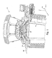
- Fig. 1 shows a front view of a stencil printer 10 in accordance with one embodiment of the present invention.
- the stencil printer 10 includes a frame 12 that supports components of the stencil printer including a controller 14, a stencil 16, and a dispensing head 100 having a dispensing slot 102 from which solder paste may be dispensed.
- the dispensing head 100 is coupled to a first plate 18 using two thumbscrews 22.
- the first plate 18 is coupled to a second plate 20 which is coupled to the frame 12 of the stencil printer 10.
- the first plate 18 is coupled to the second plate 20 in such a manner that the first plate can be moved with respect to the second plate along a z axis, the z axis being defined by the coordinate axis system 23 shown in Fig. 1.
- the first plate is moved by motors under the control of the controller 14.
- the second plate 20 is movably coupled to the frame 12 such that the second plate 20 can move with respect to the frame 12 along an x axis, the x axis also being defined by the coordinate axis system 23. As described below in further detail, the movements of the first and second plates allow the dispensing head 100 to be placed over the stencil 16 and moved across the stencil to allow printing of solder paste onto a circuit board.
- Stencil printer 10 also includes a conveyor system having rails 24 for transporting a circuit board 26 to a printing position in the stencil printer.
- the stencil printer has a number of pins 28, positioned beneath the circuit board when the circuit board is in the dispensing position. The pins are used to raise the circuit board 26 off of the rails 24 to place the circuit board in contact with, or in close proximity to, the stencil 16 when printing is to occur.
- the dispensing head 100 is configured to receive two standard SEMCO three ounce or six ounce solder paste cartridges 104 that provide solder paste to the dispensing head during a printing operation.
- Each of the solder paste cartridges 104 is coupled to one end of a pneumatic air hose 30.
- the dispensing head could be adapted to receive other standard, or non-standard, cartridges.
- the other end of each of the pneumatic air hoses is attached to a compressor that under the control of the controller 14 provides pressurized air to the cartridges to force solder paste to flow from the cartridges into the dispense head 100 and onto the screen 16.
- Mechanical devices, such as a piston may be used in addition to, or in place of, air pressure to force the solder paste from the SEMCO cartridges into the dispensing head.
- the controller 14 is implemented using a personal computer using the Microsoft DOS or Windows® NT operating system with application specific software to control the operation of the stencil printer as described herein.
- the stencil printer 10 operates as follows. A circuit board 26 is loaded into the stencil printer using the conveyor rails 24. The dispensing head is then lowered in the z direction until it is in contact with the stencil 16. Pressurized air is provided to the cartridges 104 while the dispensing head is moved in the x direction across the stencil 16. The pressurized air forces solder paste out the cartridges and creates pressure on the solder paste in the dispensing head forcing solder paste from the dispensing slot of the dispensing head through apertures in the stencil 16 and onto the circuit board 26. Once the dispensing head 100 has fully traversed the stencil 16, the circuit board is lowered back onto the conveyor rails 24 and transported from the printer so that a second circuit board may be loaded into the printer.
- the dispensing head is moved across the stencil in the direction opposite to that used for the first circuit board.
- a squeegee arm (as described below) could swing in to contain the solder paste in the dispenser, and the dispenser can then be lifted in the z direction and moved back to its original position to prepare to print on the second circuit board using a similar direction stroke. Further description of the operation and construction of the dispensing head 100 are provided below with reference to Figs. 2-5.
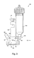
- the dispensing head 100 includes a housing 105 coupled to two supporting arms 106. At one end of each of the supporting arms 106 are thumbscrews 22 that provide for easy removal and installation of the dispensing head 100.
- the housing 105 has two ports 108 that are adapted to receive a standard SEMCO solder paste cartridge.
- the dispensing head is adapted to receive two SEMCO cartridges, however, the dispensing head may be adapted to include more or less cartridges than the two shown herein.
- the number of cartridges used is selected based on the length L of the dispensing head and the capacity of the cartridge used. The length L is determined in part based on the width of the circuit boards to be printed upon.
- the dispensing head may be replaced by a new dispensing head having a length L sized for the new circuit boards.
- the effective length of the slot 102 may also be reduced to accommodate smaller circuit boards by partially covering a portion of the slot.
- the housing 105 includes a cylindrical chamber 110 in which solder paste received from the SEMCO cartridges is stored prior to being dispensed onto the stencil.
- the interior walls of the chamber 110 are coated with a material having a low coefficient of friction.
- Other materials, having a wide range of coefficients of friction, are used for the coating to create a desired laminar flow of solder paste in the chamber.
- a number of different coatings having a variety of coefficients of friction may be used to create the desired laminar flow.
- the housing has two inwardly facing blades 112 and 114.
- Each of the inwardly facing blades has a length approximately equal to the length L of the slot, a width equal to approximately 0.138 inches, and a thickness of approximately 0.004 to 0.010 inches.
- Each of the blades 112 and 114 in one embodiment of the present invention, is made from spring steel. At each end of the blades is a side dam 103. While other materials such as plastic could be used to make the blades, the use of spring steel provides long life with continued resiliency.
- Each of the blades is arranged to provide an angle of approximately 15 degrees between the blade and the top surface of the stencil. Depending in part on the material used to make the blades and the speed at which the material dispenser traverses the stencil, the blades could be oriented at angles other than 15 degrees.
- the dispensing head 100 further includes a pressure sensor 116 and a temperature controller 120.
- a pressure sensor 116 and a temperature controller 120 Incorporated within the temperature controller is a thermoelectric device and a temperature sensor.
- the pressure sensor 116 and the temperature controller 120 are coupled to the controller 14 through cables 118 and 122 respectively.
- the controller 14 is configured to measure the pressure and the temperature of the solder paste within the chamber 110 based on signals received from the sensors, and the controller controls the pressure and temperature by adjusting the force applied to the solder paste in the cartridges and by controlling the thermoelectric device contained in the temperature controller.
- the pressure of the solder paste is maintained in the chamber by applying pressurized air at approximately 3-15 pounds per square inch to each of the cartridges 104.
- the temperature of the solder paste in the chamber is maintained during the printing operation at approximately 68 degrees Fahrenheit.
- the pressure sensor is implemented using a pressure transducer with a programmable regulator and the temperature controller is implemented using a temperature probe with a thermoelectric device that can provide cooling as well as heating of the solder paste.
- the stencil printer 10 operates by forcing solder paste from the dispensing head 100 onto the stencil using air pressure applied to each of the SEMCO cartridges as the dispensing head moves across the stencil.
- the blades 112 and 114 contact the top surface of the stencil.
- one of the blades 112 and 114 will be a trailing blade and will scrape any excess solder paste off the stencil.
- blade 112 will be the trailing blade removing any excess solder paste from the stencil.
- the orientation of the blades and the use of a cylindrical chamber in the dispensing head causes the solder paste within the chamber 110 to roll or flow in the direction of arrow 124 when the dispensing head is moved in the direction of arrow 122.
- the movement of the solder paste within the chamber causes mixing and shearing of the solder paste which helps to maintain the desired temperature and viscosity of the solder paste.
- the coating for the internal walls of the chamber 110 allows the solder paste to move freely within the chamber.
- the controller 14 turns off the pressurized air source, prior to lifting the dispensing head. This causes the solder paste to remain in the chamber 110 when the dispensing head is lifted and effectively reduces the amount of solder paste that is left on the stencil when printing is complete.
- a solder gathering squeegee arm may be used to remove excess solder paste.
- a solder gathering squeegee arm that could be used in embodiments of the present invention is described in U.S. Patent No. 5,044,306, which is incorporated herein by reference.
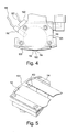
- Fig. 6 shows a solder gathering arm 130 incorporated into the dispensing head 100.
- the solder gathering arm includes a squeegee 131.
- the solder gathering arm is mounted to a bracket 132 which in turn is mounted to one or both of the supporting arms 106.
- the solder gathering arm is mounted to the bracket 132 using a rotatable joint 134, and the bracket 132 is movable with respect to the supporting arms 106 in the direction shown by arrow 122.
- the solder gathering arm operates as follows. When the dispensing head 100 is lifted slightly off of the stencil, the bracket 132 is moved in the direction of arrow 122, and the solder gathering arm is rotated in the direction shown by arrow 136 causing the squeegee 131 to scrape along the stencil and remove any excess solder on the stencil. The rotation of the solder gathering arm and the movement of the bracket 132 is accomplished using motors or actuators under the control of the controller 14.
- the blades 112 and 114 may be attached to motors or actuators that under the control of the controller cause the blades to move towards each other, scraping any excess solder paste from the screen and completely closing the slot 102.
- a pair of movable blades in addition to blades 112 and 114, may be mounted to the dispensing head and be movable towards each other to scrape excess solder paste from the stencil.
- the solder applicator includes a rotatable member that mixes solder paste in the solder applicator.
- Embodiments of the present invention described above may also be incorporated in a dual track stencil printer such as those described in U.S. Patent Application No. 08/802,934, filed February 21, 1997, which is incorporated herein by reference.
- Embodiments of the present invention described above include standard SEMCO cartridges for loading solder paste into the dispensing head. Other removable cartridges may be used in place of the SEMCO cartridges. However, it is desirable to use a standard replaceable cartridge.
- the chamber of dispensing heads in embodiments of the present invention have been described as being cylindrical.
- the dispensing head need not be cylindrical, but rather, other shapes having a substantially circular cross-section to allow rolling of the solder paste within the chamber to create a substantially laminar flow may also be used.
- the chamber is generally kidney-shaped, and the specific shape is programmable for controlling the flow of solder paste within the chamber based on the specific solder paste material used, the speed of the dispensing head across the stencil and based on any other factors.
- the dispensing head of embodiments of the present invention is described as being used with a stencil printer.
- Stencil printers such as the Ultraprint 3000 stencil printer and the AP Series stencil printer, both available from MPM Corporation of Franklin, MA, can readily be adapted for use with embodiments of the present invention.
- Embodiments of the present invention overcome problems associated with prior art stencil printers by providing dispensing heads and stencil printers that effectively remove excess solder paste from the stencil.
- the pressure applied to the solder paste to force it through apertures in the stencil is precisely controlled using a closed loop feedback system.
- a printer for printing a viscous material at predetermined positions forming a pattern on a substrate comprising:
- the material dispenser may be constructed and arranged to be movable along a first axis across the device while the viscous material is being dispensed from the chamber.
- the chamber may have a cylindrical axis extending along a length of the chamber, and wherein the cylindrical axis is orthogonal to the first axis.
- An interior surface of the chamber may be coated with a coating material having a low coefficient of friction to allow mixing of the viscous material within the chamber when the material dispenser is moved across the device.
- the printer may further comprise a temperature controller, coupled to the material dispenser, to modify temperature of the viscous material within the dispenser.
- the material dispenser may include at least one port to receive pressurized air to provide air pressure to the chamber to force the viscous material from the chamber.
- the material dispenser may include a pressure sensor to sense pressure within the chamber, and wherein the printer further comprises a controller coupled to the pressure sensor that senses the pressure within the chamber and controls the pressurized air provided through the port to maintain the pressure within the chamber at a desired value.
- the material dispenser may include a temperature sensor to sense temperature of the viscous material within the chamber, and wherein the controller controls the temperature controller to maintain the temperature at a desired value.
- the material dispenser may be adapted to receive a removable cartridge that supplies the viscous material to the chamber, the chamber having an inlet to receive the viscous material from the removable cartridge.
- the pressurized air may be provided to the cartridge to force the viscous material from the cartridge into the chamber.
- the material dispenser may be adapted to receive at least one removable cartridges.
- the opening of the chamber may be elongated about an axis that is parallel to the cylindrical axis.
- the material dispenser may further include a pair of inwardly facing blades that contact the device during printing to prevent excess material from remaining on the device.
- Each of the blades may be made from spring steel.
- the viscous material may be solder paste and the device a stencil for printing solder paste on a circuit board.
- the material dispenser may be movable in a vertical direction to allow the material dispenser to be lifted off of the device.
- the printer may further comprise a material gathering arm that collects excess viscous material remaining on the device when the material dispenser is lifted off of the device.
- the printer may further comprise a heater, coupled to the material dispenser, to heat the viscous material within the dispenser.
- the material dispenser may include a temperature sensor to sense temperature of the viscous material within the chamber, and wherein the printer further comprises a controller that controls the heater to maintain the temperature at a desired value.
- the material dispenser may include at least one port to receive pressurized air to provide air pressure to the chamber to force the viscous material from the chamber.
- the material dispenser may include a pressure sensor to sense pressure within the chamber, and the printer further comprise a controller coupled to the pressure sensor that senses the pressure within the chamber and controls the pressurized air provided through the port to maintain the pressure within the chamber at a desired value.
- the material dispenser may be adapted to receive a removable cartridge that supplies the viscous material to the chamber, the chamber having an inlet to receive the viscous material from the removable cartridge.
- the pressurized air may be provided to the cartridge to force the viscous material from the cartridge into the chamber.
- the material dispenser may be adapted to receive at least one removable cartridge.
- the opening of the chamber may be elongated about an axis that is parallel to the cylindrical axis, and the material dispenser further include a pair of inwardly facing blades that contact the device during printing to prevent excess material from remaining on the device.
- Each of the blades may be made from spring steel.
- the material dispenser may be movable in a vertical direction to allow the material dispenser to be lifted off of the device, and wherein the printer further comprises a wiping squeegee and a material gathering head that collect excess viscous material remaining on the device when the material dispenser is lifted off of the device.
- a printer for printing a viscous material at predetermined positions forming a pattern on a substrate comprising:
- the printer may be adapted to provide pressurized air to the cartridge to force viscous material from the cartridge into the chamber and from the chamber through the perforations in the device and onto the substrate.
- the material dispenser may include a pressure sensor to sense pressure within the chamber, and the printer further comprise a controller coupled to the pressure sensor that senses the pressure within the chamber and controls the pressurized air to maintain the pressure within the chamber at a desired value. comprising a heater, coupled to the material dispenser, to heat the viscous material within the dispenser.
- the material dispenser may include a temperature sensor to sense temperature of the viscous material within the chamber, and the printer further may comprise a controller that controls the heater to maintain the temperature at a desired value.
- the material dispenser may further include a pair of inwardly facing blades that contact the device during printing to prevent excess material from remaining on the device.
- Each of the blades may be made from spring steel.
- the viscous material may be solder paste and the device is a stencil for printing solder paste on a circuit board.
- the material dispenser may be movable in a vertical direction to allow the material dispenser to be lifted off of the device, and the printer may further comprise a material gathering arm that collects excess viscous material remaining on the device when the material dispenser is lifted off of the device.
- a material dispenser for dispensing a viscous material onto a stencil of a printer comprising:
- An interior surface of the chamber may be coated with a coating material having a low coefficient of friction to allow mixing of the viscous material within the chamber when the material dispenser is moved across the device.
Landscapes
- Engineering & Computer Science (AREA)
- Mechanical Engineering (AREA)
- Manufacturing & Machinery (AREA)
- Microelectronics & Electronic Packaging (AREA)
- Screen Printers (AREA)
- Electric Connection Of Electric Components To Printed Circuits (AREA)
- Encapsulation Of And Coatings For Semiconductor Or Solid State Devices (AREA)
- Non-Metallic Protective Coatings For Printed Circuits (AREA)
- Manufacturing Of Printed Circuit Boards (AREA)
Applications Claiming Priority (3)
| Application Number | Priority Date | Filing Date | Title |
|---|---|---|---|
| US08/966,057 US5947022A (en) | 1997-11-07 | 1997-11-07 | Apparatus for dispensing material in a printer |
| US966057 | 1997-11-07 | ||
| EP98956382A EP1035940B1 (fr) | 1997-11-07 | 1998-10-30 | Appareil a deposer des matieres sur un substrat |
Related Parent Applications (1)
| Application Number | Title | Priority Date | Filing Date |
|---|---|---|---|
| EP98956382A Division EP1035940B1 (fr) | 1997-11-07 | 1998-10-30 | Appareil a deposer des matieres sur un substrat |
Publications (1)
| Publication Number | Publication Date |
|---|---|
| EP1410866A2 true EP1410866A2 (fr) | 2004-04-21 |
Family
ID=25510864
Family Applications (2)
| Application Number | Title | Priority Date | Filing Date |
|---|---|---|---|
| EP98956382A Expired - Lifetime EP1035940B1 (fr) | 1997-11-07 | 1998-10-30 | Appareil a deposer des matieres sur un substrat |
| EP20030029962 Withdrawn EP1410866A2 (fr) | 1997-11-07 | 1998-10-30 | Méthode et dispositif d'apport de matière sur un substrat |
Family Applications Before (1)
| Application Number | Title | Priority Date | Filing Date |
|---|---|---|---|
| EP98956382A Expired - Lifetime EP1035940B1 (fr) | 1997-11-07 | 1998-10-30 | Appareil a deposer des matieres sur un substrat |
Country Status (5)
| Country | Link |
|---|---|
| US (1) | US5947022A (fr) |
| EP (2) | EP1035940B1 (fr) |
| AT (1) | ATE257053T1 (fr) |
| DE (1) | DE69820905T2 (fr) |
| WO (1) | WO1999024211A1 (fr) |
Cited By (1)
| Publication number | Priority date | Publication date | Assignee | Title |
|---|---|---|---|---|
| EP1144150B1 (fr) * | 1999-01-21 | 2006-05-31 | Speedline Technologies, Inc. | Procede et appareil de distribution de substance dans une imprimante |
Families Citing this family (73)
| Publication number | Priority date | Publication date | Assignee | Title |
|---|---|---|---|---|
| US6101937A (en) * | 1997-02-12 | 2000-08-15 | Minami Co., Ltd. | Screen printing machine having paste dispensers and a squeegee unit |
| US6453810B1 (en) | 1997-11-07 | 2002-09-24 | Speedline Technologies, Inc. | Method and apparatus for dispensing material in a printer |
| GB9903146D0 (en) * | 1998-09-10 | 1999-04-07 | Williams David G | Method and apparatus for applying a viscous or paste material onto a substrate |
| JP3058454U (ja) * | 1998-10-14 | 1999-06-18 | 谷電機工業株式会社 | 印刷用ペースト供給装置 |
| DE19854494C2 (de) * | 1998-11-25 | 2001-07-26 | Heidelberger Druckmasch Ag | Vorrichtung zur Farbversorgung eines Farbwerkes einer Druckmaschine |
| US6158338A (en) * | 1998-12-22 | 2000-12-12 | Dek Printing Machines Limited | Cassette for holding and dispensing a viscous material for use in an apparatus for depositing the viscous material on a substrate |
| US6511301B1 (en) | 1999-11-08 | 2003-01-28 | Jeffrey Fugere | Fluid pump and cartridge |
| US6957783B1 (en) | 1999-01-26 | 2005-10-25 | Dl Technology Llc | Dispense tip with vented outlets |
| US7207498B1 (en) | 2000-01-26 | 2007-04-24 | Dl Technology, Llc | Fluid dispense tips |
| WO2000048837A1 (fr) * | 1999-02-16 | 2000-08-24 | Dek Printing Machines Limited | Dispositif et procede permettant le depot d'un materiau visqueux |
| JP3066383B1 (ja) * | 1999-06-23 | 2000-07-17 | アスリートエフエー株式会社 | クリ―ムはんだ印刷装置及びその印刷方法 |
| US6981664B1 (en) | 2000-01-26 | 2006-01-03 | Dl Technology Llc | Fluid dispense tips |
| US6892959B1 (en) * | 2000-01-26 | 2005-05-17 | Dl Technology Llc | System and method for control of fluid dispense pump |
| JP3646603B2 (ja) * | 2000-02-17 | 2005-05-11 | 松下電器産業株式会社 | スクリーン印刷装置およびスクリーン印刷方法 |
| US7040523B2 (en) * | 2000-04-04 | 2006-05-09 | Dek International Gmbh | Method and apparatus for applying viscous or paste material onto a substrate |
| SE518640C2 (sv) * | 2000-07-11 | 2002-11-05 | Mydata Automation Ab | Förfarande, anordning för applicering av ett visköst medium på ett substrat, anordning för applicering av ytterligare visköst medium samt användningen av screentryckning |
| SE518642C2 (sv) * | 2000-07-11 | 2002-11-05 | Mydata Automation Ab | Förfarande, anordning för att förse ett substrat med visköst medium, anordning för korrigering av applikationsfel samt användningen av utskjutnings- organ för korrigering av appliceringsfel |
| DE10045359A1 (de) * | 2000-09-14 | 2002-03-28 | Gerald Hecht | Vorrichtung zum Aufbringen von Lotpaste auf eine Leiterplatte |
| US6626106B2 (en) | 2001-04-17 | 2003-09-30 | Speedline Technologies, Inc. | Cleaning apparatus in a stencil printer |
| US6571701B1 (en) | 2001-05-04 | 2003-06-03 | Speedline Technologies, Inc. | Stirring mechanism for viscous-material printer and method of printing |
| US6983867B1 (en) | 2002-04-29 | 2006-01-10 | Dl Technology Llc | Fluid dispense pump with drip prevention mechanism and method for controlling same |
| CN100333905C (zh) * | 2002-05-29 | 2007-08-29 | 谷电机工业株式会社 | 丝网印刷设备 |
| WO2003106176A1 (fr) * | 2002-06-18 | 2003-12-24 | Matsushita Electric Industrial Co. Ltd. | Contenant de pate pour serigraphie et dispositif de serigraphie |
| US7331482B1 (en) | 2003-03-28 | 2008-02-19 | Dl Technology, Llc | Dispense pump with heated pump housing and heated material reservoir |
| US20040244612A1 (en) * | 2003-03-28 | 2004-12-09 | Speedline Technologies, Inc. | Method and apparatus for printing viscous material |
| US6955120B2 (en) * | 2003-03-28 | 2005-10-18 | Speedline Technologies, Inc. | Pressure control system for printing a viscous material |
| JP4653088B2 (ja) * | 2003-07-14 | 2011-03-16 | ノードソン コーポレーション | 個別量の粘性材料を分配するための装置及び方法 |
| US7249558B2 (en) * | 2004-07-15 | 2007-07-31 | Speedline Technologies, Inc. | Solder paste dispenser for a stencil printer |
| US8128753B2 (en) * | 2004-11-19 | 2012-03-06 | Massachusetts Institute Of Technology | Method and apparatus for depositing LED organic film |
| US8986780B2 (en) | 2004-11-19 | 2015-03-24 | Massachusetts Institute Of Technology | Method and apparatus for depositing LED organic film |
| US20070012746A1 (en) * | 2005-07-18 | 2007-01-18 | Chien-Yen Lu | Heating type accelerator for soldering paste |
| US8707559B1 (en) | 2007-02-20 | 2014-04-29 | Dl Technology, Llc | Material dispense tips and methods for manufacturing the same |
| EP2155493A4 (fr) * | 2007-06-14 | 2010-08-11 | Massachusetts Inst Technology | Procédé et appareil pour déposer des films |
| US8556389B2 (en) | 2011-02-04 | 2013-10-15 | Kateeva, Inc. | Low-profile MEMS thermal printhead die having backside electrical connections |
| US8899171B2 (en) | 2008-06-13 | 2014-12-02 | Kateeva, Inc. | Gas enclosure assembly and system |
| US8383202B2 (en) * | 2008-06-13 | 2013-02-26 | Kateeva, Inc. | Method and apparatus for load-locked printing |
| US10434804B2 (en) | 2008-06-13 | 2019-10-08 | Kateeva, Inc. | Low particle gas enclosure systems and methods |
| US12018857B2 (en) | 2008-06-13 | 2024-06-25 | Kateeva, Inc. | Gas enclosure assembly and system |
| US9048344B2 (en) | 2008-06-13 | 2015-06-02 | Kateeva, Inc. | Gas enclosure assembly and system |
| US9604245B2 (en) | 2008-06-13 | 2017-03-28 | Kateeva, Inc. | Gas enclosure systems and methods utilizing an auxiliary enclosure |
| US11975546B2 (en) | 2008-06-13 | 2024-05-07 | Kateeva, Inc. | Gas enclosure assembly and system |
| US12064979B2 (en) | 2008-06-13 | 2024-08-20 | Kateeva, Inc. | Low-particle gas enclosure systems and methods |
| US20100188457A1 (en) * | 2009-01-05 | 2010-07-29 | Madigan Connor F | Method and apparatus for controlling the temperature of an electrically-heated discharge nozzle |
| US8864055B2 (en) | 2009-05-01 | 2014-10-21 | Dl Technology, Llc | Material dispense tips and methods for forming the same |
| KR101441737B1 (ko) * | 2009-05-01 | 2014-09-17 | 카티바, 인크. | 유기 증기 인쇄용 장치 및 방법 |
| US8331844B2 (en) | 2010-04-14 | 2012-12-11 | Xerox Corporation | Proof printing using recycled marking material |
| JP5408158B2 (ja) * | 2011-03-09 | 2014-02-05 | パナソニック株式会社 | スクリーン印刷装置およびスクリーン印刷方法 |
| JP5408157B2 (ja) * | 2011-03-09 | 2014-02-05 | パナソニック株式会社 | スクリーン印刷装置およびスクリーン印刷方法 |
| JP5408159B2 (ja) * | 2011-03-09 | 2014-02-05 | パナソニック株式会社 | スクリーン印刷装置およびスクリーン印刷方法 |
| CN103229325B (zh) | 2011-04-08 | 2018-02-16 | 卡帝瓦公司 | 用于利用面式滚筒印制的方法和设备 |
| US8939073B2 (en) | 2012-02-08 | 2015-01-27 | Illinois Tool Works Inc. | Print head for stencil printer |
| US9725225B1 (en) | 2012-02-24 | 2017-08-08 | Dl Technology, Llc | Micro-volume dispense pump systems and methods |
| CN105900258A (zh) | 2013-12-26 | 2016-08-24 | 科迪华公司 | 电子装置的热加工 |
| JP6051411B2 (ja) * | 2013-12-27 | 2016-12-27 | パナソニックIpマネジメント株式会社 | ペースト供給装置、スクリーン印刷機及びペースト供給方法 |
| KR102050152B1 (ko) | 2014-01-21 | 2020-01-08 | 카티바, 인크. | 전자 장치 인캡슐레이션을 위한 기기 및 기술 |
| JP6221063B2 (ja) * | 2014-03-17 | 2017-11-01 | パナソニックIpマネジメント株式会社 | スクリーン印刷装置及びスクリーン印刷方法 |
| KR102390045B1 (ko) | 2014-04-30 | 2022-04-22 | 카티바, 인크. | 가스 쿠션 장비 및 기판 코팅 기술 |
| JP2016049720A (ja) * | 2014-09-01 | 2016-04-11 | パナソニックIpマネジメント株式会社 | スクリーン印刷装置およびスクリーン印刷方法 |
| US9370925B1 (en) | 2015-03-25 | 2016-06-21 | Illinois Tool Works Inc. | Stencil printer having stencil shuttle assembly |
| US9370924B1 (en) | 2015-03-25 | 2016-06-21 | Illinois Tool Works Inc. | Dual action stencil wiper assembly for stencil printer |
| US10703089B2 (en) | 2015-04-07 | 2020-07-07 | Illinois Tool Works Inc. | Edge lock assembly for a stencil printer |
| US10723117B2 (en) | 2015-04-07 | 2020-07-28 | Illinois Tool Works Inc. | Lift tool assembly for stencil printer |
| US9370923B1 (en) | 2015-04-07 | 2016-06-21 | Illinois Tool Works Inc. | Lift tool assembly for stencil printer |
| US10410599B2 (en) * | 2015-08-13 | 2019-09-10 | Samsung Electronics Co., Ltd. | Source driver integrated circuit for ompensating for display fan-out and display system including the same |
| CN106392242A (zh) * | 2016-12-02 | 2017-02-15 | 无锡职业技术学院 | 高精密超微点胶系统 |
| JP7127055B2 (ja) * | 2017-04-14 | 2022-08-29 | イリノイ トゥール ワークス インコーポレイティド | はんだペースト印刷機の自動はんだペースト付加装置 |
| US11746656B1 (en) | 2019-05-13 | 2023-09-05 | DL Technology, LLC. | Micro-volume dispense pump systems and methods |
| US20200391530A1 (en) | 2019-06-13 | 2020-12-17 | Illinois Tool Works Inc. | Multi-functional print head for a stencil printer |
| US11318549B2 (en) * | 2019-06-13 | 2022-05-03 | Illinois Tool Works Inc. | Solder paste bead recovery system and method |
| US11247286B2 (en) | 2019-06-13 | 2022-02-15 | Illinois Tool Works Inc. | Paste dispensing transfer system and method for a stencil printer |
| EP3988312A1 (fr) * | 2020-10-23 | 2022-04-27 | Nederlandse Organisatie voor toegepast- natuurwetenschappelijk Onderzoek TNO | Dispositif et procédé de remplissage de rainures |
| US11554580B1 (en) | 2021-09-09 | 2023-01-17 | Illinois Tool Works Inc. | Squeegee drip collection system for stencil printer |
| CN115734510B (zh) * | 2022-11-14 | 2026-01-23 | 同力恒业科技(天津)有限公司 | 一种smt工艺封装设备以及封装方法 |
Family Cites Families (35)
| Publication number | Priority date | Publication date | Assignee | Title |
|---|---|---|---|---|
| US3097554A (en) * | 1963-07-16 | Fluid driven mechanism | ||
| US2382920A (en) * | 1941-11-18 | 1945-08-14 | Charles F Schaefer | Stencil coating machine |
| US2571064A (en) * | 1945-11-01 | 1951-10-09 | Charles F Schaefer | Mounting for stencil screens |
| US3037457A (en) * | 1959-08-26 | 1962-06-05 | Gen Electric | Pumps |
| DE2108085C3 (de) * | 1970-03-09 | 1974-08-22 | Peter Kufstein Zimmer (Oesterreich) | Rakelrolle |
| US3921521A (en) * | 1970-07-23 | 1975-11-25 | Zimmer Peter | Squeegee device |
| CH552471A (de) * | 1972-05-30 | 1974-08-15 | Zimmer Peter | Rakeleinrichtung an schablonendruckmaschine. |
| AT321855B (de) * | 1973-04-03 | 1975-04-25 | Zimmer Johannes | Vorrichtung zum bedrucken von warenbahnen |
| US4043683A (en) * | 1974-06-20 | 1977-08-23 | Loctite Corporation | Dispensing and wiping device |
| US4023486A (en) * | 1974-08-01 | 1977-05-17 | E.T. Barwick Industries | Screen printing squeegee apparatus |
| FI52028C (fi) * | 1976-01-13 | 1977-06-10 | Outokumpu Oy | Vaahdotuskenno. |
| US4485736A (en) * | 1983-08-26 | 1984-12-04 | Strutz Jr Carl | Ink-dispensing system and method for silk-screen printing having squeegee stroke movement counter |
| US4636406A (en) * | 1984-12-31 | 1987-01-13 | Motorola, Inc. | Method and apparatus for dispensing solder paste |
| SE460779B (sv) * | 1985-02-27 | 1989-11-20 | Svecia Silkscreen Maskiner Ab | Rakelarrangemang foer en stenciltryckmaskin |
| US4622239A (en) * | 1986-02-18 | 1986-11-11 | At&T Technologies, Inc. | Method and apparatus for dispensing viscous materials |
| JPH0777665B2 (ja) * | 1986-05-16 | 1995-08-23 | 栄修 永田 | ハンダ付け方法およびハンダ付け装置 |
| US4720402A (en) * | 1987-01-30 | 1988-01-19 | American Telephone And Telegraph Company | Method for dispensing viscous material |
| DE3823200C1 (fr) * | 1988-07-08 | 1990-03-08 | Gerhard 4800 Bielefeld De Klemm | |
| US4961955A (en) * | 1988-12-20 | 1990-10-09 | Itt Corporation | Solder paste applicator for circuit boards |
| US5211311A (en) * | 1989-06-23 | 1993-05-18 | E. R. Carpenter Company, Inc. | Cartridge for a dispenser of reactive chemicals |
| US5044306A (en) * | 1990-06-11 | 1991-09-03 | Gunter Erdmann | Solder applying mechanism |
| GB2257386B (en) * | 1991-06-24 | 1995-07-05 | Tani Denki Kogyo Kk | Screen printing apparatus |
| US5309837A (en) * | 1991-06-24 | 1994-05-10 | Tani Denkikogyo Co., Ltd. | Method for screen printing of paste |
| GB2279899B (en) * | 1991-06-24 | 1995-07-05 | Tani Denki Kogyo Kk | A screen printing system |
| GB2259661A (en) * | 1991-09-18 | 1993-03-24 | Ibm | Depositing solder on printed circuit boards |
| US5320250A (en) * | 1991-12-02 | 1994-06-14 | Asymptotic Technologies, Inc. | Method for rapid dispensing of minute quantities of viscous material |
| WO1994005512A1 (fr) * | 1992-08-28 | 1994-03-17 | Bic Corporation | Stylo retractable a cartouche jetable |
| JP3345653B2 (ja) * | 1993-05-12 | 2002-11-18 | 谷電機工業株式会社 | スクリーン版クリーニング装置 |
| JP3583462B2 (ja) * | 1993-04-05 | 2004-11-04 | フォード モーター カンパニー | 電子成分のための微小はんだ付け装置および方法 |
| US5553540A (en) * | 1993-05-19 | 1996-09-10 | Tani Denkikogyo Co., Ltd. | Method for screen printing of viscous materials |
| US5407488A (en) * | 1993-10-12 | 1995-04-18 | At&T Corp. | Method and apparatus for in-situ removal of material from openings in a stencil |
| CN1077845C (zh) * | 1994-12-27 | 2002-01-16 | 福特汽车公司 | 布施粘性材料的装置 |
| CA2417989A1 (fr) * | 1995-03-01 | 1996-09-02 | Okie Tani | Methode de serigraphie et appareil servant a la mise en application de ladite methode |
| DE19541996C2 (de) * | 1995-11-10 | 1997-09-25 | David Finn | Vorrichtung zur Applikation von Verbindungsmaterialeinheiten |
| FR2754473B1 (fr) * | 1996-10-15 | 1999-02-26 | Novatec | Procede de realisation de depots de produit visqueux et/ou pateux sur un substrat a travers les ouvertures d'un pochoir et dispositif distributeur de produit |
-
1997
- 1997-11-07 US US08/966,057 patent/US5947022A/en not_active Expired - Lifetime
-
1998
- 1998-10-30 EP EP98956382A patent/EP1035940B1/fr not_active Expired - Lifetime
- 1998-10-30 AT AT98956382T patent/ATE257053T1/de not_active IP Right Cessation
- 1998-10-30 DE DE69820905T patent/DE69820905T2/de not_active Expired - Lifetime
- 1998-10-30 EP EP20030029962 patent/EP1410866A2/fr not_active Withdrawn
- 1998-10-30 WO PCT/US1998/023089 patent/WO1999024211A1/fr not_active Ceased
Cited By (1)
| Publication number | Priority date | Publication date | Assignee | Title |
|---|---|---|---|---|
| EP1144150B1 (fr) * | 1999-01-21 | 2006-05-31 | Speedline Technologies, Inc. | Procede et appareil de distribution de substance dans une imprimante |
Also Published As
| Publication number | Publication date |
|---|---|
| ATE257053T1 (de) | 2004-01-15 |
| DE69820905D1 (de) | 2004-02-05 |
| EP1035940A1 (fr) | 2000-09-20 |
| US5947022A (en) | 1999-09-07 |
| DE69820905T2 (de) | 2004-12-30 |
| EP1035940B1 (fr) | 2004-01-02 |
| WO1999024211A1 (fr) | 1999-05-20 |
Similar Documents
| Publication | Publication Date | Title |
|---|---|---|
| US5947022A (en) | Apparatus for dispensing material in a printer | |
| US6626097B2 (en) | Apparatus for dispensing material in a printer | |
| US6619198B2 (en) | Method and apparatus for dispensing material in a printer | |
| US7249558B2 (en) | Solder paste dispenser for a stencil printer | |
| US6066206A (en) | Dual track stenciling system with solder gathering head | |
| EP2812186B1 (fr) | Tête d'impression pour imprimante au pochoir | |
| US20020007789A1 (en) | Dual track stenciling system with solder gathering head | |
| US6626106B2 (en) | Cleaning apparatus in a stencil printer | |
| US6955120B2 (en) | Pressure control system for printing a viscous material | |
| WO2005082623A1 (fr) | Procedes et appareil de nettoyage de stencil | |
| US20040244612A1 (en) | Method and apparatus for printing viscous material | |
| US6571701B1 (en) | Stirring mechanism for viscous-material printer and method of printing |
Legal Events
| Date | Code | Title | Description |
|---|---|---|---|
| PUAI | Public reference made under article 153(3) epc to a published international application that has entered the european phase |
Free format text: ORIGINAL CODE: 0009012 |
|
| AC | Divisional application: reference to earlier application |
Ref document number: 1035940 Country of ref document: EP Kind code of ref document: P |
|
| AK | Designated contracting states |
Kind code of ref document: A2 Designated state(s): AT BE CH CY DE DK ES FI FR GB GR IE IT LI LU MC NL PT SE |
|
| RIN1 | Information on inventor provided before grant (corrected) |
Inventor name: BALOG, ROBERT J. Inventor name: ROSSMEISL, MARK Inventor name: FREEMAN, GARY T. |
|
| STAA | Information on the status of an ep patent application or granted ep patent |
Free format text: STATUS: THE APPLICATION HAS BEEN WITHDRAWN |
|
| 18W | Application withdrawn |
Effective date: 20050211 |