EP1410868A2 - Dispositif d'alimentation en fil de soudage avec entraínement principal et auxilliaire - Google Patents
Dispositif d'alimentation en fil de soudage avec entraínement principal et auxilliaire Download PDFInfo
- Publication number
- EP1410868A2 EP1410868A2 EP03017244A EP03017244A EP1410868A2 EP 1410868 A2 EP1410868 A2 EP 1410868A2 EP 03017244 A EP03017244 A EP 03017244A EP 03017244 A EP03017244 A EP 03017244A EP 1410868 A2 EP1410868 A2 EP 1410868A2
- Authority
- EP
- European Patent Office
- Prior art keywords
- wire
- welding wire
- welding
- conveying
- sensor
- Prior art date
- Legal status (The legal status is an assumption and is not a legal conclusion. Google has not performed a legal analysis and makes no representation as to the accuracy of the status listed.)
- Granted
Links
- 238000003466 welding Methods 0.000 title claims abstract description 371
- 238000003860 storage Methods 0.000 claims abstract description 39
- 230000001105 regulatory effect Effects 0.000 claims abstract description 10
- 238000001514 detection method Methods 0.000 claims description 34
- 238000012544 monitoring process Methods 0.000 claims description 8
- 238000000034 method Methods 0.000 abstract description 14
- 230000008569 process Effects 0.000 abstract description 10
- 230000004888 barrier function Effects 0.000 description 8
- 230000008901 benefit Effects 0.000 description 5
- 239000007789 gas Substances 0.000 description 5
- 239000004020 conductor Substances 0.000 description 4
- 230000015572 biosynthetic process Effects 0.000 description 3
- 238000010276 construction Methods 0.000 description 3
- 238000001816 cooling Methods 0.000 description 3
- 239000007788 liquid Substances 0.000 description 3
- 230000009467 reduction Effects 0.000 description 3
- XLYOFNOQVPJJNP-UHFFFAOYSA-N water Substances O XLYOFNOQVPJJNP-UHFFFAOYSA-N 0.000 description 3
- XKRFYHLGVUSROY-UHFFFAOYSA-N Argon Chemical compound [Ar] XKRFYHLGVUSROY-UHFFFAOYSA-N 0.000 description 2
- 230000001419 dependent effect Effects 0.000 description 2
- 238000013461 design Methods 0.000 description 2
- -1 CO 2 Substances 0.000 description 1
- 238000013459 approach Methods 0.000 description 1
- 229910052786 argon Inorganic materials 0.000 description 1
- 230000000712 assembly Effects 0.000 description 1
- 238000000429 assembly Methods 0.000 description 1
- 230000008859 change Effects 0.000 description 1
- 230000001276 controlling effect Effects 0.000 description 1
- 230000006378 damage Effects 0.000 description 1
- 230000003247 decreasing effect Effects 0.000 description 1
- 230000000694 effects Effects 0.000 description 1
- 238000010891 electric arc Methods 0.000 description 1
- 238000005516 engineering process Methods 0.000 description 1
- 239000001307 helium Substances 0.000 description 1
- 229910052734 helium Inorganic materials 0.000 description 1
- SWQJXJOGLNCZEY-UHFFFAOYSA-N helium atom Chemical compound [He] SWQJXJOGLNCZEY-UHFFFAOYSA-N 0.000 description 1
- 238000009434 installation Methods 0.000 description 1
- 238000004519 manufacturing process Methods 0.000 description 1
- 238000003825 pressing Methods 0.000 description 1
- 230000001681 protective effect Effects 0.000 description 1
- 238000012549 training Methods 0.000 description 1
Images



Classifications
-
- B—PERFORMING OPERATIONS; TRANSPORTING
- B23—MACHINE TOOLS; METAL-WORKING NOT OTHERWISE PROVIDED FOR
- B23K—SOLDERING OR UNSOLDERING; WELDING; CLADDING OR PLATING BY SOLDERING OR WELDING; CUTTING BY APPLYING HEAT LOCALLY, e.g. FLAME CUTTING; WORKING BY LASER BEAM
- B23K9/00—Arc welding or cutting
- B23K9/12—Automatic feeding or moving of electrodes or work for spot or seam welding or cutting
- B23K9/133—Means for feeding electrodes, e.g. drums, rolls, motors
- B23K9/1336—Driving means
Definitions
- the invention relates to a device for conveying welding wire from a wire supply to a welding torch and a wire feed system such as these in generic terms of claims 1 and 9 are described.
- the disadvantage here is that the elastically deformable element is coupled to the drive motor is so that there is a direct influence on the rotary movement on the element.
- DE 43 20 405 C2 describes a device for conveying a welding wire known from a wire supply to a welding torch in which the welding torch and a wire feed device, in particular a main drive, to the wire supply and an auxiliary drive are assigned.
- a wire storage unit with means for detecting the curvature behavior arranged of the welding wire, wherein the means by a non-contact sensor is formed.
- the sensor signals of the sensor are applied to a control device, with of the welding wire conveyors are controlled in such a way that within the wire storage unit forms a closed wire loop.
- From US 1,927,896 A is a device for conveying a welding wire from one Wire supply known to a welding torch, in turn, the welding torch and a welding wire conveying device is assigned to the wire supply.
- the Welding wire is transported in a curved path from the wire supply to the welding torch.
- the curvature behavior is controlled by a spring-loaded roller the welding wire is measured. If the tension of the welding wire increases, then the roller deflected downward, creating a contact arm or lever attached to the roller changed an adjustable resistance. This resistance is with the welding wire feeder coupled for the wire supply, whereby a regulation based on the curvature behavior of the welding wire is made.
- JP 08309536 A shows a welding system in which the welding wire is connected via a Hose package is fed to a welding torch.
- the invention has for its object a device for conveying welding wire from a wire supply to a welding torch that creates a slip-free conveyance of the welding wire is possible and a safe and simple regulation for several welding wire conveying devices used in a welding system can be achieved.
- the object of the invention is also achieved by the features in the characterizing part of the claim 1 solved. It is advantageous here that such a wire storage device Conveying movements of the welding wire received or intercepted by the wire storage and thus a simple regulation or control of the welding wire conveyor device is possible.
- Wire feeds such as a pulsed wire feed to the Welding torch or a forward and backward advancement of the welding wire can be, the delivery force or the delivery pressure on the inherent rigidity of the welding wire independently.
- FIG. 1 An exemplary embodiment is described in FIG. 1 in which it is not is an embodiment of the invention, but this is the understanding of the invention facilitated.
- a welding system or a welding device 1 for various welding processes, such as. MIG / MAG welding or TIG welding or electrode welding processes, shown.
- MIG / MAG welding or TIG welding or electrode welding processes shown.
- a Power source or a welding power source can be used.
- the welding device 1 comprises a current source 2 with a power unit 3, a control device 4 and a changeover element 5 assigned to the power unit 3 or the control device 4.
- the changeover element 5 or the control device 4 is connected to a control valve 6, which is connected in a supply line 7 for a gas 8, in particular a protective gas, such as CO 2 , helium or argon and the like, is arranged between a gas storage device 9 and a welding torch 10.
- a wire feed device 11 which is used for the MIG / MAG welding is common to be controlled, using a supply line 12 a welding wire 13 from a wire supply 14 into the area of the welding torch 10 is stirred.
- the wire feeder 11 as it is is known from the prior art, in the welding device 1, in particular in the basic housing, is integrated and is not, as shown in Fig. 1, designed as an additional device.
- the current to build an arc 15 between the welding wire 13 and one Workpiece 16 is supplied via a supply line 17 from power section 3 of current source 2 fed to the welding torch 10 or the welding wire 13, the end to be welded Workpiece 16 via a further supply line 18 also with the welding device 1, in particular with the power source 2, and is therefore connected via the arc 15 Circuit can be built.
- the welding torch can be cooled 19 10 with the interposition of a flow monitor 20 with a liquid container, In particular, a water tank 21, are connected, so that during commissioning of the welding torch 10, the cooling circuit 19, in particular one for those in the water tank 21 arranged liquid used liquid pump is started and thus a Cooling of the welding torch 10 or the welding wire can be effected.
- the welding device 1 also has an input and / or output device 22 via which the most varied welding parameters or operating modes of the welding device 1 are set can be. In this case, those set via the input and / or output device 22 are set Welding parameters are forwarded to the control device 4 and are by this then the individual components of the welding system or welding device 1 driven.
- Hose package 23 connected to the welding device 1 or the welding system.
- Hose package 23 are the individual lines from welding device 1 to welding torch 10 arranged.
- the hose package 23 is connected via a connecting device which is part of the prior art 24 connected to the welding torch 10, whereas the individual lines in the hose package 23 with the individual contacts of the welding device 1 via connection sockets or plug connections are connected.
- a corresponding strain relief of the hose package 23 is guaranteed, the hose package 23 is via a strain relief device 25 with a housing 26, in particular with the basic housing of the Welder 1, connected.
- 2 and 3 is a device for conveying welding wire 13 from a wire supply 14 to the welding torch 10 with at least one welding wire conveying device 27 and a device, in particular a further welding wire conveying device 28, to build up a conveying force, in particular a main drive 29 and an auxiliary drive 30, shown, one in the wire feed between the welding wire conveying devices 27, 28 occurring conveying force or a pressure force in the welding wire 13 via Detection means, in particular a pipe sensor 31, is detected.
- Detection means in particular a pipe sensor 31
- the extent of a transverse movement of the welding wire 13 becomes the conveying force and / or speed of at least the welding wire conveyor device 27 and / or the device, in particular the further welding wire conveyor device 28.
- the extent of Transverse movement of the welding wire 13 can be determined by a target / actual comparison, the setpoint being determined as a value within that range in which the detection means no signal detected.
- the main drive 29 is on the welding torch 10 or arranged in the area of the welding torch 10 and the auxiliary drive 30 to the wire supply 14 or arranged or assigned in the area of the wire supply 14.
- the wire feed from the wire supply 14 to the welding torch 10 takes place via the Hose package 23 or a guide device, in particular one in the hose package 23 or the guide device arranged soul.
- the welding wire 13 is Determination of a force fluctuation or a conveying force or a pressure force of the Welding wire assigned to the tube sensor 31. This is between the welding wire conveyor devices 27, 28, in particular the main drive and the auxiliary drive.
- the welding wire conveyor device 27, 28, in particular the main drive 29 and the Auxiliary drive 30, consist of a drive motor 32, 33, as shown schematically, and a or more drive elements 34 acting on the welding wire 13, in particular Drive rollers, formed.
- the sensor in particular the tube sensor 31, is in the longitudinal direction of the welding wire 13, that is, arranged in the welding wire conveying direction or assigned to the welding wire 13.
- the tube sensor 31 is through a housing 35, in particular through a tube or a tubular Element, and a wire inlet guide 36 and a wire outlet stirrer 37, the wire inlet guide 36 and the wire outlet guide 37 from one electrically conductive material are formed.
- the tube sensor 31, however, is made of an electrical formed conductive material and has an inner diameter 38 of the tube, the is larger than an outer diameter of the welding wire 13.
- the tube sensor 31 or the housing 35 or the tube of the tube sensor 31 is included connected to a detector unit 39.
- the detector unit 39 is in turn equipped with a welding wire feed device 27, in particular with the auxiliary drive 30, preferably with the drive element 34, electrically connected.
- the detector unit 39 is also with a for the welding wire conveyor device 27 and the device, in particular the other Welding wire feeder 28, required speed controller unit 40, wherein one of the drive motors 32, 33, which is connected to the speed controller unit 40 are driven depending on the detector unit 39, i.e. the welding wire feeder 27 or the device, in particular the further welding wire conveying device 28, is kept at a constant speed and the speed of the other Welding wire feeder 27 or 28 based on a signal from the detector unit 39 is regulated.
- the speed controller unit 40 is connected to the control device 4, so that a User or welder via the input and / or output device 22, which is schematic is shown, can set a wire feed speed and thus of the Control device 4 send corresponding setpoints to the speed controller unit 40 can.
- the regulation or control is then carried out by the speed controller unit 40 independent of the control device 4 of the welding device 1.
- the control device 4 connected to the power section 3.
- the power section 3 is also on the welding lines 17, 18 with the welding torch 10 or via a contact socket with the Welding wire 13 and the workpiece 16 connected, whereby the arc 15 between the welding wire 13 and the workpiece 16 can be constructed.
- the welding wire conveyor devices 27, 28 When a welding process is activated, the welding wire conveyor devices 27, 28 from the speed controller unit 40 a corresponding signal for a speed that for a certain preset wire feed speed is required. Doing so the main drive 29 is regulated by the speed control unit 40 in such a way that there is a constant Wire feed speed sets.
- the detection of the conveying force or the pressure force takes place by the sensor, in particular the tube sensor 31, transversely to the conveying direction of the welding wire 13, i.e. that the sensor, in particular the tube sensor 31, which surrounds the welding wire 13, so that the welding wire 13 is passed through the sensor.
- the welding wire 13 runs with an optimal conveying force in the middle of the tube sensor 31.
- This has an inner diameter 38 which is larger than the outer diameter of the welding wire 13, so that the welding wire 13 is in the area of the pipe sensor 31 can move freely. This ensures that if the conveying power is too high the welding wire 13 can deflect in this area, i.e.
- the sensor in particular the pipe sensor 31, thus avoids or deflects of the welding wire 13 running in the middle or in a middle position of the tube sensor determined on the basis of the conveying force or the pressure force on the welding wire 13, the welding wire 13 with an optimal conveying force or an optimal pressing force of the auxiliary drive 30 in the direction of the main drive 29 in the sensor, in particular in the Pipe sensor 31 runs in the middle or in the middle position and with a further increase the conveying force from the medium, in particular from the central position, is pressed, as in Fig. 3 is shown.
- This deflection or deflection of the welding wire 13 is caused by the speed control unit 40 caused because the speed or a wire feed speed of the auxiliary drive 30 is higher than the speed or the wire feed speed of the main drive 29 on the welding torch 10.
- the speed controller unit 40 one of the two welding wire conveying devices 27, 28, in particular of the main drive 29, kept constant, whereas the speed of the other welding wire conveying device 27, 28, in particular of the auxiliary drive 30, is regulated or reduced, i.e.
- the conveying force or the compressive force on the welding wire 13 is reduced because of Main drive 29 keeps the welding wire 13 constant in the direction of the welding torch 10 promotes and fed from the auxiliary drive 30 less welding wire 13 from the wire supply 14 becomes.
- the evasion or the deflection of the welding wire 13 increases Pipe sensor 31 again. That that the speed controller unit 40 when receiving a signal from the detector unit 39 the speed of the auxiliary drive 30, in particular that Welding wire feed device 27, 28 which is assigned to the wire supply 14, reduced or the speed of the main drive 29 increases.
- the speed controller unit 40 upon receipt of a signal from the detector unit 39 the welding wire feeders 27, 28 regulates such that the conveying force or the compressive force on the welding wire 13 is reduced or limited and thus the evasion or the deflection of the Welding wire 13 is lifted in the tube sensor 31.
- a signal is sent from the detector unit 39 to the speed control unit 40 if the welding wire 13 inside the sensor, in particular the tube sensor 31, is deflected in this way is that it touches the housing 35 of the sensor, in particular the pipe sensor 31 and thus a short circuit between that acting on the welding wire 13 Welding wire feed device 27, in particular the drive element 34, and the housing 35 of the sensor, in particular of the tube sensor 31, is generated by the welding wire 13, so that the speed control unit 40 with the reduction or limitation of the conveying force can start.
- the control of the auxiliary drive 30 can be done with all of the prior art known methods are carried out.
- the speed control from the speed controller unit 40 for the auxiliary drive 30 takes place until there is no signal from the detector unit 39 more is sent, i.e. the short circuit is removed, or the regulation is dependent a presettable period of time, i.e. that the speed exceeds a predetermined and stored curve shape is changed over a certain period of time.
- the speed control unit 40 the speed or the wire feed speed of the auxiliary drive 30 again slightly increased, so that if a course close occurs again, another regulation is carried out.
- FIG. 4 shows a further exemplary embodiment for the sensor, in particular the pipe sensor 31, shown, the functional principle corresponding to the figures described above.
- the tube sensor 31 is now designed such that in the interior of the housing 35 elements are arranged with which the deflection or the conveying force on the Welding wire 13 can be detected. It is possible, for example, that inside, in particular in the interior of the sensor, in particular the tube sensor 31, at least one Light barrier 41, as shown with dashed lines, is arranged, with about this the deflection of the welding wire 13 from the central position of the sensor, in particular of the tube sensor 31, is determined, i.e.
- the light barrier 41 is constructed can be and thus with a deflection of the welding wire 13 due to a high conveying force this light barrier 41 is interrupted, so that a signal from the Detector unit 39 to the speed controller unit 40 for controlling the welding wire feed devices 27, 28 is sent.
- the detector unit 39 with the elements of Pipe sensor 31 connected, which form a signal when activated, so that the further Connection of the tube sensor 31 to the auxiliary drive 30 can be omitted.
- the detector unit 39 with the elements of Pipe sensor 31 connected, which form a signal when activated, so that the further Connection of the tube sensor 31 to the auxiliary drive 30 can be omitted.
- At least one Pressure element 42 is arranged which, when touched, is proportional to a touch force emits an electrical signal and in turn the deflection of the welding wire 13 can be detected.
- a deflection device is preferably in the interior of the housing 35 43, as shown schematically with dash-dotted lines.
- the deflector 43 has the task of welding wire 13 already with optimal conveying power from the middle position, indicated by dashed lines, to print the housing 35, so that a directional specification is achieved for the deflection of the welding wire 13. It goes without saying possible that a closed housing 35 is no longer necessary, but that the welding wire 13 also runs freely over the deflection device 43 can be and the elements are arranged on the opposite side.
- FIG. 4 is a special training the wire inlet guide 36 and the wire outlet guide 37. These show an expanding course in the direction of the interior of the housing 35 of the sensor so that when the wire is threaded, the welding wire 13 is deflected such that it is without additional aids can be guided through the sensor.
- 5 and 6 is another embodiment for the detection or determination the deflection of the welding wire 13 shown.
- the sensor is now switched off a pressure sensor 44 which is attached to the housing of the welding device 1, wherein the welding wire 13 is in turn passed through the pressure sensor 44.
- the pressure sensor 44 is constructed such that it consists of an outer and an inner ring 45, 46 there are pressure elements 47 in between, the inner diameter now of the inner ring 46 only slightly larger than the outer diameter of the welding wire 13 or the inner diameter when using a core for guiding the welding wire 13 of the ring 46 is slightly larger than the outer diameter of the soul.
- Such a construction of the sensor, in particular the pressure sensor 44, achieves that a partial or partial deflection of the welding wire 13 from it Normal position at at least one detector point in the area between the welding wire conveyor devices 27, 28 is detected by the sensor, in particular the pressure sensor 44.
- the welding wire 13 cannot because of the narrow guidance in the pressure sensor deviate from its conveying position, so that only a rudimentary deflection is detected or established can be. This has the advantage that there are no injuries or kinks the surface of the welding wire 13 can come.
- the special design of the pressure sensor 44 which is guided around the welding wire 13 or has the advantage that the welding wire 13 in the pressure sensor 44 can deflect any direction, but only a small number of pressure elements 47 is necessary, since the pressure forces generated by the inner ring 46 Welding wire 13 can be divided onto the existing pressure elements 47.
- Another The advantage of such a pressure sensor 44 is that it is permanent Monitoring of the welding wire 13 can be carried out since the adjustment paths or Deviations of the welding wire 13 are minimal and thus the welding wire 13 with a maximum funding capacity can be promoted.
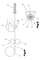
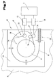
- FIG. 7 shows an exemplary embodiment of a device for conveying welding wire 13 from a wire supply 14 to a welding torch 10 (see FIG. 1 or 2), wherein A welding wire conveyor device 27 is assigned to at least the wire supply 14.
- the wire feed from the wire supply 14 to the welding torch 10 takes place via the hose package 23 or a guide device, in particular one in the hose package 23 or the guide device arranged core.
- a guide device in particular one in the hose package 23 or the guide device arranged core.
- the welding wire 13 in the wire storage unit 48 has a detection means 49, in particular a sensor assigned to detect the curvature behavior of the welding wire 13 is.
- the detection means 49 can be formed by an angle sensor or a rotary resistor 50 the detection means 49 via a lever 51 rigidly attached to it is connected to the welding wire 13 in the wire storage unit 48, so that the detection means 49 for monitoring the loop-shaped course of the welding wire 13 is formed around the wire supply 14. Furthermore, the detection means 49 with a controller unit 52 for the welding wire conveyor device 27 for passing on information for the Regulation of at least one welding wire conveyor device 27. This controller unit 52 sent to the speed controller unit 40 for the drive motor - not shown - and preferably a corresponding signal to the control device 4 of the welding device 1, so that depending on the signal from the controller unit 52, the speed or the conveying speed is increased or decreased by the speed control unit 40.
- the structure of the welding device 1 can take place as in the previously described FIGS. 1 to 6, so that the Welding torch 10 and the wire supply 14 each have a welding wire conveying device 27, 28, in particular a main drive 29 and an auxiliary drive 30, is assigned, the For the sake of clarity, only the wire supply 14 with the wire storage unit 48 and the associated one Welding wire feed device 27 is shown. Of course it is possible that a construction with only one welding wire conveyor device 27 or 28 can take place.
- the lever 51 of the detection means 49 is movable connected to the welding wire 13, so that when the loop formation changes of the welding wire 13, this lever 51 can be moved by the welding wire 13.
- the detection means 49 in particular the angle sensor or the rotational resistance 50, with the lever 51, preferably within the loop-shaped course of the welding wire 13, arranged. So that the welding wire 13 is loop-shaped in the wire storage unit 48 can be stirred, it is possible that several freely movable bearing points or Guide elements are arranged.
- the Welding wire 13 in a core in particular in a plastic core, so that a appropriate rigidity is achieved and by appropriate attachment of the soul this assumes a loop-shaped formation.
- the wire storage unit 48 through a housing box 53 of the Housing 26 of the welding device 1 is formed, as is indicated schematically.
- the wire supply 14 In the wire storage unit 48 or the housing box 53 of the welding device 1 is the wire supply 14, the welding wire conveyor device 27, in particular its drive elements 34, and the detection means 49 arranged, the attachment or storage of the individual Elements on a rear wall of the housing box 53, in particular on the housing 26 of the welding device 1, takes place and during operation of the welding device 1 this housing box 53 with a cover or a side part of the housing 26, as already for the Storage or arrangement of the wire supply 14 in the welding device 1 from the prior art Technology is known, is closed.
- the speed controller unit 40 the welding wire conveying device 27 to a preset welding wire conveying speed regulated, the welding wire conveyor device 27 welding wire 13 of the wire supply 14 from a preferably round wire reel.
- the welding wire 13 leads before entering the hose package 23, which is shown schematically, or one Guide device a loop-shaped, freely movable circulation around the wire supply 14 by, i.e. that the welding wire 13 by the welding wire conveyor device 27 in Direction of the welding torch 10 (see Fig.1 or 2) is transported, this after of the welding wire conveying device 27 has a loop-shaped or circular circulation performs around the wire reel or the wire supply 14.
- the wire supply 14 is rotatable in the Center of the loop-shaped course of the welding wire 13 in the wire storage unit 48 arranged.
- Such a design ensures that after the welding wire conveyor 27 a so-called wire storage is created, so that possible effects on the Hose package 23 or special wire feeds, for example a pulse-shaped or forward and backward conveyance of the welding wire 13 during a welding process, can be intercepted or compensated by this wire storage.
- the movement of the welding wire 13 in the wire storage unit 48 is indicated by an arrow 54 schematically indicated, so that it can be seen that, for example, the welding wire 13 at too big a pull or if too much conveyance of another welding wire conveying device 28 moves in the direction of the wire supply 14.
- This movement is via the detection means 49 detected and forwarded to the speed controller unit 40, whereupon after the Falling below a target value for the change in the welding wire 13 in the wire storage unit 48 now from the speed control unit 40, the conveying speed is increased and thus this movement can be compensated.
- the conveying speed is too high of the welding wire 13 by the welding wire conveying device 27 or with a backward movement or backward conveyance of the welding wire 13 by the further welding wire conveying device 28 becomes an increase in the loop diameter of the welding wire 13 in the wire storage unit 48 until exceeded a further setpoint by reducing the conveying speed of the Welding wire feed device 27 the loop diameter is reduced again.
- This use of the wire storage advantageously achieves that changes in welding wire delivery do not directly affect the drive elements 34 of the Welding wire feed device 27 impact and at the same time with a backward movement of the welding wire 13, the opposing resistance is greatly reduced, i.e. that with a backward movement of the welding wire 13 without such a wire storage the welding wire 13 from the welding torch 10 to that arranged in the welding device 1 Welding wire conveyor device 27 would have to be pressed or this welding wire conveyor device 27 must also initiate backward funding.
- FIG 8 shows a further exemplary embodiment in which a wire conveyor system for conveying and monitoring the welding wire 13 from the wire supply 14 to Welding torch 10 is shown.
- a combination of the previously described FIG. 1 is used to 7 used, i.e. that in a welding system of the wire storage unit 48 and the sensor, in particular the tube sensor 31, are used.
- the functional description is dispensed with, as this is from the previously described 1 to 7 can be seen.
- a welding wire conveying device 27 is arranged and after exiting the wire storage unit 48 for the detection of the Conveying force or the pressure force of the welding wire 13, the welding wire conveying devices 27 and 28, in particular the main drive 29 on the welding torch 10 and the auxiliary drive 30 are arranged in the area of the wire supply 14, i.e. that for this structure now three welding wire conveyor devices 27, 28 are arranged by the speed control unit 40 can be controlled independently.
- the detector unit 39 and the controller unit 52 can be integrated in the speed controller unit 40 or that the speed controller unit 40 is controlled by the control device 4 of the welding device 1 is realized.
- the invention can relate to a method with which the monitoring a conveying force or a compressive force on a welding wire when conveying Welding wire 13 from a wire supply 14 to a welding torch 10, with at least a welding wire conveyor device 27 and a device, in particular another Welding wire conveying device 28, for applying a in the conveying direction to the Welding wire 13 acting conveying force, e.g. a compressive force in a wire feeder between the welding wire conveying device 27 and the device directly via a Detection means, in particular a sensor, is detected.
- a Detection means in particular a sensor
- the invention can be a device for monitoring as an independent solution a conveying force or a compressive force on a welding wire 13 when conveying Welding wire 13 from a wire supply 14 to a welding torch 10 with a welding wire feed device 27, a device for building a conveying force, a detection means 49 for detecting the conveying force or the compressive force in the welding wire 13, wherein the wire supply 14 a welding wire feed device 27 and the welding torch 10 a device, in particular a further welding wire conveying device 28, for assembly is assigned to a conveying force, the wire conveying from the wire supply 14 to the Welding torch 10 via a hose package 23 or a guide device, in particular a core arranged in the hose package 23 or in the guide device, and the welding wire 13 for determining a fluctuation in the conveying force, e.g.
- At least one detection means 49 is associated with the welding wire 13.
- the detection means 49 in particular a sensor, e.g. a pipe sensor 31, between the welding wire feed device 27 and the device, in particular the other Welding wire conveying device 28 may be arranged and for determining a deflection or a partial deflection when the inherent stiffness of the welding wire is exceeded 13 serves from a conveying direction.
- a solution according to the invention can also include a device for monitoring a conveying force or a pressure force on a welding wire 13 when conveying welding wire 13 from a wire supply 14 to a welding torch 10 with a detection means, in particular with a sensor.
- the sensor in particular a pipe sensor, can be used 31, through a housing 35, in particular through a tube or a tubular element a wire inlet guide 36 and a wire outlet guide 37 are formed, these are formed from a non-electrically conductive material, and the tube of the tube sensor 31 be formed from an electrically conductive material and an inner diameter of the tube be larger than an outer diameter of the welding wire 13.
- Another method according to the invention can be used to monitor a conveying force or a pressure force on a welding wire when conveying welding wire (13) from one Wire supply 14 to a welding torch 10 may be provided. It can be from a detector unit 39 a signal to a speed control unit 40 are sent when the Welding wire 13 inside a sensor, in particular a tube sensor 31, deflected in this way is that it touches a housing 26 of the sensor, in particular the pipe sensor 31 and thus a short circuit between that acting on the welding wire 13 Welding wire conveyor device 27, 28, in particular a drive element 34 of the Welding wire feed device 27, 28, and the housing 26 of the sensor, in particular the Pipe sensor 31, is generated by the welding wire 13.
- FIGS. 1; 2, 3; 4; 5, 6; 7; 8 executions shown Form the subject of independent solutions according to the invention.
- the related Objects and solutions according to the invention are the detailed descriptions of these figures refer to.
Landscapes
- Engineering & Computer Science (AREA)
- Physics & Mathematics (AREA)
- Plasma & Fusion (AREA)
- Mechanical Engineering (AREA)
- Butt Welding And Welding Of Specific Article (AREA)
- Wire Processing (AREA)
- Arc Welding Control (AREA)
- Coating With Molten Metal (AREA)
- Arc Welding In General (AREA)
- Electrical Discharge Machining, Electrochemical Machining, And Combined Machining (AREA)
- Ropes Or Cables (AREA)
- Control Of Conveyors (AREA)
Applications Claiming Priority (3)
| Application Number | Priority Date | Filing Date | Title |
|---|---|---|---|
| AT196899 | 1999-11-19 | ||
| AT0196899A AT411032B (de) | 1999-11-19 | 1999-11-19 | Verfahren und vorrichtung zum überwachen einer förderkraft |
| EP00978926A EP1253990B1 (fr) | 1999-11-19 | 2000-11-15 | Dispositif d'acheminement de fil de soudure avec entrainements principal et auxiliaire |
Related Parent Applications (1)
| Application Number | Title | Priority Date | Filing Date |
|---|---|---|---|
| EP00978926A Division EP1253990B1 (fr) | 1999-11-19 | 2000-11-15 | Dispositif d'acheminement de fil de soudure avec entrainements principal et auxiliaire |
Publications (3)
| Publication Number | Publication Date |
|---|---|
| EP1410868A2 true EP1410868A2 (fr) | 2004-04-21 |
| EP1410868A3 EP1410868A3 (fr) | 2005-02-09 |
| EP1410868B1 EP1410868B1 (fr) | 2009-10-21 |
Family
ID=3524958
Family Applications (2)
| Application Number | Title | Priority Date | Filing Date |
|---|---|---|---|
| EP00978926A Expired - Lifetime EP1253990B1 (fr) | 1999-11-19 | 2000-11-15 | Dispositif d'acheminement de fil de soudure avec entrainements principal et auxiliaire |
| EP03017244A Expired - Lifetime EP1410868B1 (fr) | 1999-11-19 | 2000-11-15 | Dispositif d'alimentation en fil de soudage avec entraînement principal et auxilliaire |
Family Applications Before (1)
| Application Number | Title | Priority Date | Filing Date |
|---|---|---|---|
| EP00978926A Expired - Lifetime EP1253990B1 (fr) | 1999-11-19 | 2000-11-15 | Dispositif d'acheminement de fil de soudure avec entrainements principal et auxiliaire |
Country Status (8)
| Country | Link |
|---|---|
| US (1) | US6831251B1 (fr) |
| EP (2) | EP1253990B1 (fr) |
| AT (4) | AT411032B (fr) |
| AU (1) | AU1644301A (fr) |
| DE (2) | DE50010781D1 (fr) |
| DK (1) | DK1253990T3 (fr) |
| ES (1) | ES2333946T3 (fr) |
| WO (1) | WO2001038034A1 (fr) |
Cited By (2)
| Publication number | Priority date | Publication date | Assignee | Title |
|---|---|---|---|---|
| DE102009058869A1 (de) * | 2009-12-18 | 2011-06-22 | Alexander Binzel Schweisstechnik GmbH & Co. KG, 35418 | Verfahren zum Steuern des Vorschubes der abnutzbaren Drahtelektrode von Schweiß-und/oder Lötanlagen sowie eine solche Schweiß-und/oder Lötanlage |
| WO2024132758A1 (fr) * | 2022-12-22 | 2024-06-27 | Compagnie Generale Des Etablissements Michelin | Compensateur à boucle pour la régulation de l'alimentation d'une imprimante 3d |
Families Citing this family (40)
| Publication number | Priority date | Publication date | Assignee | Title |
|---|---|---|---|---|
| AT411338B (de) * | 2001-04-24 | 2003-12-29 | Fronius Schweissmasch Prod | Vorrichtung sowie verfahren zum fehlererkennen bei der schweissdrahtförderung |
| JP3812381B2 (ja) * | 2001-07-30 | 2006-08-23 | 松下電器産業株式会社 | 溶接ワイヤ送給装置 |
| US6969823B2 (en) * | 2002-07-23 | 2005-11-29 | Illinois Tool Works Inc. | Method and apparatus for controlling a welding system |
| US20050189335A1 (en) * | 2002-07-23 | 2005-09-01 | Gerd Huismann | Method and apparatus for feeding wire to a welding arc |
| US6963048B2 (en) * | 2002-07-23 | 2005-11-08 | Illinois Tool Works Inc. | Method and apparatus for welding with mechanical arc control |
| US7165707B2 (en) | 2002-07-23 | 2007-01-23 | Illinois Tool Works Inc. | Method and apparatus for feeding wire to a welding arc |
| US6984806B2 (en) | 2002-07-23 | 2006-01-10 | Illinois Tool Works Inc. | Method and apparatus for retracting and advancing a welding wire |
| US7102099B2 (en) | 2002-07-23 | 2006-09-05 | Illinois Tool Works Inc. | Method and apparatus for feeding wire to a welding arc |
| AT412765B (de) * | 2003-07-03 | 2005-07-25 | Fronius Int Gmbh | Schweissbrenner |
| AT500755B8 (de) * | 2003-10-23 | 2007-02-15 | Fronius Int Gmbh | Drahtförderung mit konstantem moment |
| AT413659B (de) * | 2004-01-26 | 2006-04-15 | Fronius Int Gmbh | Schweissdraht-speichervorrichtung |
| RU2288820C1 (ru) * | 2005-06-21 | 2006-12-10 | Томский политехнический университет | Способ управления механизмом импульсной подачи сварочной проволоки |
| US9555495B2 (en) * | 2007-05-31 | 2017-01-31 | Lincoln Global, Inc. | Automatic welding wire feed adjuster |
| JP2010052021A (ja) * | 2008-08-29 | 2010-03-11 | Daihen Corp | ワイヤのバッファ形成機構、ワイヤ供給装置、および溶接/溶射ロボット |
| RU2429111C2 (ru) * | 2009-07-06 | 2011-09-20 | Государственное образовательное учреждение высшего профессионального образования "Томский политехнический университет" | Комбинированный способ импульсного управления процессом сварки плавящимся электродом |
| DE102009045400B3 (de) * | 2009-10-06 | 2011-06-09 | Bayerische Motoren Werke Aktiengesellschaft | Fügevorrichtung für ein stoffschlüssiges Fügen mittels eines Zusatzwerkstoffes |
| AT508895B1 (de) * | 2010-01-14 | 2011-05-15 | Erema | Läuferscheibe |
| US10183353B2 (en) * | 2010-09-17 | 2019-01-22 | Illinois Tool Works Inc. | Method and apparatus for welding with reduced spatter |
| US9162313B2 (en) * | 2010-12-23 | 2015-10-20 | Lincoln Global, Inc. | Wire feeder wire drive design |
| AT511213B1 (de) * | 2011-05-27 | 2012-10-15 | Fronius Int Gmbh | Verfahren zum ermitteln des anpressdruck-sollwerts für die förderung eines schweissdrahts einer schweissvorrichtung und schweissvorrichtung |
| JP6155151B2 (ja) * | 2013-09-20 | 2017-06-28 | 株式会社ダイヘン | ワイヤ送給装置 |
| CN104801825B (zh) * | 2014-01-27 | 2020-02-14 | 株式会社大亨 | 进给机构、电弧系统 |
| US10343231B2 (en) * | 2014-05-28 | 2019-07-09 | Awds Technologies Srl | Wire feeding system |
| US10010962B1 (en) | 2014-09-09 | 2018-07-03 | Awds Technologies Srl | Module and system for controlling and recording welding data, and welding wire feeder |
| US10350696B2 (en) * | 2015-04-06 | 2019-07-16 | Awds Technologies Srl | Wire feed system and method of controlling feed of welding wire |
| US9975728B2 (en) | 2015-09-10 | 2018-05-22 | Sidergas Spa | Wire container lid, wire container and wire feeding system |
| US11370052B2 (en) * | 2016-03-11 | 2022-06-28 | Daihen Corporation | Arc welding system and wire feeding device |
| US10906120B2 (en) * | 2016-06-10 | 2021-02-02 | Illinois Tool Works Inc. | Methods and apparatus to provide a consistent electrode state for welding |
| CN109803783A (zh) * | 2016-10-18 | 2019-05-24 | 株式会社达谊恒 | 焊丝进给装置以及电弧焊接装置 |
| DE102017111535A1 (de) * | 2017-05-26 | 2018-11-29 | Carl Cloos Schweißtechnik Gesellschaft mit beschränkter Haftung | Ausgleichsvorichtung für einen Schweißdraht |
| CN107696504A (zh) * | 2017-10-18 | 2018-02-16 | 浙江秉鹏自动化科技有限公司 | 超声波焊接机送丝检测机构 |
| JP7039301B2 (ja) * | 2018-01-24 | 2022-03-22 | 株式会社ダイヘン | ワイヤ送給装置、アーク溶接装置及びワイヤ送給方法 |
| JP6985972B2 (ja) * | 2018-04-03 | 2021-12-22 | 株式会社ダイヘン | ワイヤ送給装置 |
| JP6975090B2 (ja) * | 2018-04-03 | 2021-12-01 | 株式会社ダイヘン | 溶接システム |
| JP6992226B2 (ja) * | 2018-04-12 | 2022-01-13 | 株式会社ダイヘン | ワイヤ送給システム、および、溶接システム |
| US12420349B2 (en) * | 2018-12-21 | 2025-09-23 | Daihen Corporation | Arc welding control method |
| JP7290904B2 (ja) | 2019-09-27 | 2023-06-14 | 株式会社ダイヘン | アーク溶接方法 |
| US11174121B2 (en) | 2020-01-20 | 2021-11-16 | Awds Technologies Srl | Device for imparting a torsional force onto a wire |
| US11278981B2 (en) | 2020-01-20 | 2022-03-22 | Awds Technologies Srl | Device for imparting a torsional force onto a wire |
| AU2023216842A1 (en) * | 2022-08-18 | 2024-03-07 | Relativity Space, Inc. | Multiple Wire Additive Manufacturing |
Citations (3)
| Publication number | Priority date | Publication date | Assignee | Title |
|---|---|---|---|---|
| US1927896A (en) | 1930-05-22 | 1933-09-26 | Westinghouse Electric & Mfg Co | Automatic welding device |
| DE4320405A1 (de) | 1993-06-21 | 1994-12-22 | Fraunhofer Ges Forschung | Verfahren und Vorrichtung zur schlupffreien Förderung von Draht |
| JPH08309536A (ja) | 1995-05-24 | 1996-11-26 | Babcock Hitachi Kk | 溶接用ワイヤ送給装置 |
Family Cites Families (14)
| Publication number | Priority date | Publication date | Assignee | Title |
|---|---|---|---|---|
| US3107870A (en) * | 1959-02-13 | 1963-10-22 | Wunderlich Spring Machinery Co | Wire feeding apparatus |
| US3483340A (en) * | 1966-06-03 | 1969-12-09 | Nat Res Dev | Overload detector for wire feed system |
| US3586221A (en) * | 1969-08-28 | 1971-06-22 | Air Reduction | Torque control of multiple motors for uniform feed of welding wire |
| BG24442A1 (en) * | 1975-09-24 | 1978-03-10 | Iski Samokovli | Device for modular feed of electrode bodies at great distances |
| DE2739351C2 (de) * | 1977-09-01 | 1983-06-01 | Aurel Prof. Dipl.-Ing. Dr.-Ing. 5354 Weilerswist Dobranis | Drahtführungs-Kontaktdüse |
| GB2120692B (en) * | 1982-05-14 | 1986-07-16 | Welding Inst | Improvements relating to wire supplying |
| US4934627A (en) | 1987-09-11 | 1990-06-19 | Macneil Daniel J | De-reeler |
| AT394675B (de) * | 1988-11-03 | 1992-05-25 | Fronius Schweissmasch | Drahtvorschubeinrichtung fuer ein schutzgas-schweissgeraet |
| DE69700088T2 (de) * | 1996-03-15 | 1999-05-27 | L'oreal S.A., Paris | Behälter mit einem dekorativen Etikett und Verfahren zu dessen Herstellung |
| US6091048A (en) * | 1997-05-16 | 2000-07-18 | Illinois Tool Works Inc. | Welding machine with automatic parameter setting |
| DE19732379C2 (de) * | 1997-07-25 | 1999-05-27 | Kuka Schweissanlagen Gmbh | Verfahren und Vorrichtung zum Fördern von Schweißdraht |
| US5916464A (en) * | 1997-08-26 | 1999-06-29 | Geiger; Michael B. | Welding force feedback wire feed system |
| DE29716009U1 (de) * | 1997-09-06 | 1997-10-23 | Dinse GmbH, 22041 Hamburg | Vorrichtung zur Überwachung der Fördergeschwindigkeit einer Schweißdrahtelektrode, insbesondere beim Lichtbogenschweißen |
| DE19855033A1 (de) * | 1998-11-28 | 2000-05-31 | Abb Patent Gmbh | Einrichtung zum Fördern von Schweißdraht |
-
1999
- 1999-11-19 AT AT0196899A patent/AT411032B/de not_active IP Right Cessation
-
2000
- 2000-11-15 ES ES03017244T patent/ES2333946T3/es not_active Expired - Lifetime
- 2000-11-15 DK DK00978926T patent/DK1253990T3/da active
- 2000-11-15 EP EP00978926A patent/EP1253990B1/fr not_active Expired - Lifetime
- 2000-11-15 AT AT03017244T patent/ATE446155T1/de not_active IP Right Cessation
- 2000-11-15 EP EP03017244A patent/EP1410868B1/fr not_active Expired - Lifetime
- 2000-11-15 WO PCT/AT2000/000302 patent/WO2001038034A1/fr not_active Ceased
- 2000-11-15 DE DE50010781T patent/DE50010781D1/de not_active Expired - Lifetime
- 2000-11-15 DE DE50015771T patent/DE50015771D1/de not_active Expired - Lifetime
- 2000-11-15 AT AT00978926T patent/ATE299775T1/de not_active IP Right Cessation
- 2000-11-15 AU AU16443/01A patent/AU1644301A/en not_active Abandoned
- 2000-11-15 US US10/130,565 patent/US6831251B1/en not_active Expired - Fee Related
-
2001
- 2001-10-25 AT AT0169401A patent/AT411341B/de not_active IP Right Cessation
Patent Citations (3)
| Publication number | Priority date | Publication date | Assignee | Title |
|---|---|---|---|---|
| US1927896A (en) | 1930-05-22 | 1933-09-26 | Westinghouse Electric & Mfg Co | Automatic welding device |
| DE4320405A1 (de) | 1993-06-21 | 1994-12-22 | Fraunhofer Ges Forschung | Verfahren und Vorrichtung zur schlupffreien Förderung von Draht |
| JPH08309536A (ja) | 1995-05-24 | 1996-11-26 | Babcock Hitachi Kk | 溶接用ワイヤ送給装置 |
Cited By (4)
| Publication number | Priority date | Publication date | Assignee | Title |
|---|---|---|---|---|
| DE102009058869A1 (de) * | 2009-12-18 | 2011-06-22 | Alexander Binzel Schweisstechnik GmbH & Co. KG, 35418 | Verfahren zum Steuern des Vorschubes der abnutzbaren Drahtelektrode von Schweiß-und/oder Lötanlagen sowie eine solche Schweiß-und/oder Lötanlage |
| DE102009058869B4 (de) * | 2009-12-18 | 2014-07-17 | Alexander Binzel Schweisstechnik Gmbh & Co. Kg | Verfahren zum Steuern des Vorschubes der abnutzbaren Drahtelektrode von Schweiß-und/oder Lötanlagen sowie eine solche Schweiß-und/oder Lötanlage |
| WO2024132758A1 (fr) * | 2022-12-22 | 2024-06-27 | Compagnie Generale Des Etablissements Michelin | Compensateur à boucle pour la régulation de l'alimentation d'une imprimante 3d |
| FR3144041A1 (fr) * | 2022-12-22 | 2024-06-28 | Compagnie Generale Des Etablissements Michelin | Compensateur à boucle pour la régulation de l’alimentation d’une imprimante 3d |
Also Published As
| Publication number | Publication date |
|---|---|
| EP1410868B1 (fr) | 2009-10-21 |
| ATE299775T1 (de) | 2005-08-15 |
| EP1253990B1 (fr) | 2005-07-20 |
| ATE446155T1 (de) | 2009-11-15 |
| ES2333946T3 (es) | 2010-03-03 |
| DE50015771D1 (de) | 2009-12-03 |
| US6831251B1 (en) | 2004-12-14 |
| DK1253990T3 (da) | 2005-11-14 |
| DE50010781D1 (de) | 2005-08-25 |
| EP1410868A3 (fr) | 2005-02-09 |
| AT411032B (de) | 2003-09-25 |
| AU1644301A (en) | 2001-06-04 |
| WO2001038034A1 (fr) | 2001-05-31 |
| EP1253990A1 (fr) | 2002-11-06 |
| ATA196899A (de) | 2003-02-15 |
| ATA16942001A (de) | 2003-05-15 |
| AT411341B (de) | 2003-12-29 |
Similar Documents
| Publication | Publication Date | Title |
|---|---|---|
| EP1410868A2 (fr) | Dispositif d'alimentation en fil de soudage avec entraínement principal et auxilliaire | |
| EP1644154B1 (fr) | Chalumeau soudeur a unite d'entrainement et a moyens de reserve tampon de fil | |
| EP1708842B1 (fr) | Dispositif de stockage de fil d'apport | |
| EP1626832B1 (fr) | Dispositif d'amortissement pour un fil de soudure et poste de soudure | |
| DE102012218487B4 (de) | Verfahren und Vorrichtung zur Herstellung einer dreidimensionalen Struktur an der Oberfläche eines metallischen Werkstücks | |
| AT506998B1 (de) | Kontaktrohr für einen schweissbrenner | |
| DE102007006114B4 (de) | Verfahren zur Regelung der Vorschubgeschwindigkeit eines Drahtes und Vorrichtung zum Zuführen von Draht in einem thermischen Fügeprozeß | |
| EP1677941B2 (fr) | Procede pour piloter et/ou regler un processus de soudage | |
| DE212004000048U1 (de) | Schweißanlage | |
| DE2140545A1 (de) | Vorrichtung zum automatischen Lichtbogenschweißen durch programmierte Takte | |
| EP2830807B1 (fr) | Dispositif de soudage comportant deux chalumeaux de soudage et une unité de commande destinée à initier l'amorçage lumineux ; procédé de soudage destiné au soudage en mettant en oeuvre deux processus de soudage pilotés par un processus d'initiation adapté | |
| CH680272A5 (fr) | ||
| EP1381488B1 (fr) | Dispositif et procede de detection de defauts lors de l'avance d'un fil d'apport | |
| EP4054784B1 (fr) | Procédé et dispositif pour la soudure d'un cordon de soudure | |
| AT500755A1 (de) | Drahtförderung mit konstantem moment | |
| WO2004033141A1 (fr) | Element sectionneur pour une installation robotique | |
| EP2313229B1 (fr) | Procédé et dispositif pour façonner l'extrémité d'un fil de soudage | |
| AT500653A1 (de) | Drahtfördervorrichtung | |
| AT514318A4 (de) | Verfahren zum Durchführen eines Schweißprozesses, Schweißgerät und Drahtrolle für ein solches Schweißgerät | |
| DE3508854C1 (de) | Lichtbogenschweißanlage mit kontinuierlich zuführbarer blanker Drahtelektrode | |
| DE202004007184U1 (de) | Antriebseinheit zum Fördern eines Schweißdrahtes | |
| AT7924U1 (de) | Antriebseinheit zum fördern eines schweissdrahtes |
Legal Events
| Date | Code | Title | Description |
|---|---|---|---|
| PUAI | Public reference made under article 153(3) epc to a published international application that has entered the european phase |
Free format text: ORIGINAL CODE: 0009012 |
|
| 17P | Request for examination filed |
Effective date: 20030730 |
|
| AC | Divisional application: reference to earlier application |
Ref document number: 1253990 Country of ref document: EP Kind code of ref document: P |
|
| AK | Designated contracting states |
Kind code of ref document: A2 Designated state(s): AT BE CH CY DE DK ES FI FR GB GR IE IT LI LU MC NL PT SE TR |
|
| AX | Request for extension of the european patent |
Extension state: SI |
|
| PUAL | Search report despatched |
Free format text: ORIGINAL CODE: 0009013 |
|
| AK | Designated contracting states |
Kind code of ref document: A3 Designated state(s): AT BE CH CY DE DK ES FI FR GB GR IE IT LI LU MC NL PT SE TR |
|
| AX | Request for extension of the european patent |
Extension state: SI |
|
| AKX | Designation fees paid |
Designated state(s): AT BE CH CY DE DK ES FI FR GB GR IE IT LI LU MC NL PT SE TR |
|
| 17Q | First examination report despatched |
Effective date: 20050812 |
|
| GRAP | Despatch of communication of intention to grant a patent |
Free format text: ORIGINAL CODE: EPIDOSNIGR1 |
|
| GRAS | Grant fee paid |
Free format text: ORIGINAL CODE: EPIDOSNIGR3 |
|
| GRAA | (expected) grant |
Free format text: ORIGINAL CODE: 0009210 |
|
| AC | Divisional application: reference to earlier application |
Ref document number: 1253990 Country of ref document: EP Kind code of ref document: P |
|
| AK | Designated contracting states |
Kind code of ref document: B1 Designated state(s): AT BE CH CY DE DK ES FI FR GB GR IE IT LI LU MC NL PT SE TR |
|
| AX | Request for extension of the european patent |
Extension state: SI |
|
| REG | Reference to a national code |
Ref country code: GB Ref legal event code: FG4D Free format text: NOT ENGLISH |
|
| REG | Reference to a national code |
Ref country code: CH Ref legal event code: EP |
|
| REG | Reference to a national code |
Ref country code: IE Ref legal event code: FG4D |
|
| REF | Corresponds to: |
Ref document number: 50015771 Country of ref document: DE Date of ref document: 20091203 Kind code of ref document: P |
|
| REG | Reference to a national code |
Ref country code: ES Ref legal event code: FG2A Ref document number: 2333946 Country of ref document: ES Kind code of ref document: T3 |
|
| NLV1 | Nl: lapsed or annulled due to failure to fulfill the requirements of art. 29p and 29m of the patents act | ||
| PG25 | Lapsed in a contracting state [announced via postgrant information from national office to epo] |
Ref country code: FI Free format text: LAPSE BECAUSE OF FAILURE TO SUBMIT A TRANSLATION OF THE DESCRIPTION OR TO PAY THE FEE WITHIN THE PRESCRIBED TIME-LIMIT Effective date: 20091021 Ref country code: SE Free format text: LAPSE BECAUSE OF FAILURE TO SUBMIT A TRANSLATION OF THE DESCRIPTION OR TO PAY THE FEE WITHIN THE PRESCRIBED TIME-LIMIT Effective date: 20091021 Ref country code: PT Free format text: LAPSE BECAUSE OF FAILURE TO SUBMIT A TRANSLATION OF THE DESCRIPTION OR TO PAY THE FEE WITHIN THE PRESCRIBED TIME-LIMIT Effective date: 20100222 |
|
| REG | Reference to a national code |
Ref country code: IE Ref legal event code: FD4D |
|
| BERE | Be: lapsed |
Owner name: FRONIUS INTERNATIONAL GMBH Effective date: 20091130 |
|
| PG25 | Lapsed in a contracting state [announced via postgrant information from national office to epo] |
Ref country code: MC Free format text: LAPSE BECAUSE OF NON-PAYMENT OF DUE FEES Effective date: 20091130 |
|
| REG | Reference to a national code |
Ref country code: CH Ref legal event code: PL |
|
| PG25 | Lapsed in a contracting state [announced via postgrant information from national office to epo] |
Ref country code: DK Free format text: LAPSE BECAUSE OF FAILURE TO SUBMIT A TRANSLATION OF THE DESCRIPTION OR TO PAY THE FEE WITHIN THE PRESCRIBED TIME-LIMIT Effective date: 20091021 Ref country code: IE Free format text: LAPSE BECAUSE OF FAILURE TO SUBMIT A TRANSLATION OF THE DESCRIPTION OR TO PAY THE FEE WITHIN THE PRESCRIBED TIME-LIMIT Effective date: 20091021 |
|
| PLBE | No opposition filed within time limit |
Free format text: ORIGINAL CODE: 0009261 |
|
| STAA | Information on the status of an ep patent application or granted ep patent |
Free format text: STATUS: NO OPPOSITION FILED WITHIN TIME LIMIT |
|
| 26N | No opposition filed |
Effective date: 20100722 |
|
| PG25 | Lapsed in a contracting state [announced via postgrant information from national office to epo] |
Ref country code: BE Free format text: LAPSE BECAUSE OF NON-PAYMENT OF DUE FEES Effective date: 20091130 Ref country code: CH Free format text: LAPSE BECAUSE OF NON-PAYMENT OF DUE FEES Effective date: 20091130 Ref country code: GR Free format text: LAPSE BECAUSE OF FAILURE TO SUBMIT A TRANSLATION OF THE DESCRIPTION OR TO PAY THE FEE WITHIN THE PRESCRIBED TIME-LIMIT Effective date: 20100122 Ref country code: LI Free format text: LAPSE BECAUSE OF NON-PAYMENT OF DUE FEES Effective date: 20091130 |
|
| PG25 | Lapsed in a contracting state [announced via postgrant information from national office to epo] |
Ref country code: AT Free format text: LAPSE BECAUSE OF NON-PAYMENT OF DUE FEES Effective date: 20091115 |
|
| PG25 | Lapsed in a contracting state [announced via postgrant information from national office to epo] |
Ref country code: LU Free format text: LAPSE BECAUSE OF NON-PAYMENT OF DUE FEES Effective date: 20091115 |
|
| PG25 | Lapsed in a contracting state [announced via postgrant information from national office to epo] |
Ref country code: TR Free format text: LAPSE BECAUSE OF FAILURE TO SUBMIT A TRANSLATION OF THE DESCRIPTION OR TO PAY THE FEE WITHIN THE PRESCRIBED TIME-LIMIT Effective date: 20091021 |
|
| PG25 | Lapsed in a contracting state [announced via postgrant information from national office to epo] |
Ref country code: CY Free format text: LAPSE BECAUSE OF FAILURE TO SUBMIT A TRANSLATION OF THE DESCRIPTION OR TO PAY THE FEE WITHIN THE PRESCRIBED TIME-LIMIT Effective date: 20091021 |
|
| PG25 | Lapsed in a contracting state [announced via postgrant information from national office to epo] |
Ref country code: NL Free format text: LAPSE BECAUSE OF FAILURE TO SUBMIT A TRANSLATION OF THE DESCRIPTION OR TO PAY THE FEE WITHIN THE PRESCRIBED TIME-LIMIT Effective date: 20091021 |
|
| PGFP | Annual fee paid to national office [announced via postgrant information from national office to epo] |
Ref country code: GB Payment date: 20131127 Year of fee payment: 14 |
|
| PGFP | Annual fee paid to national office [announced via postgrant information from national office to epo] |
Ref country code: FR Payment date: 20131128 Year of fee payment: 14 Ref country code: IT Payment date: 20131113 Year of fee payment: 14 |
|
| PGFP | Annual fee paid to national office [announced via postgrant information from national office to epo] |
Ref country code: ES Payment date: 20131128 Year of fee payment: 14 |
|
| PGFP | Annual fee paid to national office [announced via postgrant information from national office to epo] |
Ref country code: DE Payment date: 20141117 Year of fee payment: 15 |
|
| GBPC | Gb: european patent ceased through non-payment of renewal fee |
Effective date: 20141115 |
|
| REG | Reference to a national code |
Ref country code: FR Ref legal event code: ST Effective date: 20150731 |
|
| PG25 | Lapsed in a contracting state [announced via postgrant information from national office to epo] |
Ref country code: GB Free format text: LAPSE BECAUSE OF NON-PAYMENT OF DUE FEES Effective date: 20141115 |
|
| PG25 | Lapsed in a contracting state [announced via postgrant information from national office to epo] |
Ref country code: FR Free format text: LAPSE BECAUSE OF NON-PAYMENT OF DUE FEES Effective date: 20141201 |
|
| REG | Reference to a national code |
Ref country code: ES Ref legal event code: FD2A Effective date: 20151229 |
|
| PG25 | Lapsed in a contracting state [announced via postgrant information from national office to epo] |
Ref country code: IT Free format text: LAPSE BECAUSE OF NON-PAYMENT OF DUE FEES Effective date: 20141115 |
|
| PG25 | Lapsed in a contracting state [announced via postgrant information from national office to epo] |
Ref country code: ES Free format text: LAPSE BECAUSE OF NON-PAYMENT OF DUE FEES Effective date: 20141116 |
|
| REG | Reference to a national code |
Ref country code: DE Ref legal event code: R119 Ref document number: 50015771 Country of ref document: DE |
|
| PG25 | Lapsed in a contracting state [announced via postgrant information from national office to epo] |
Ref country code: DE Free format text: LAPSE BECAUSE OF NON-PAYMENT OF DUE FEES Effective date: 20160601 |