EP1410934A1 - Système de bâchage/débâchage, notamment pour un véhicule de fret - Google Patents
Système de bâchage/débâchage, notamment pour un véhicule de fret Download PDFInfo
- Publication number
- EP1410934A1 EP1410934A1 EP03020583A EP03020583A EP1410934A1 EP 1410934 A1 EP1410934 A1 EP 1410934A1 EP 03020583 A EP03020583 A EP 03020583A EP 03020583 A EP03020583 A EP 03020583A EP 1410934 A1 EP1410934 A1 EP 1410934A1
- Authority
- EP
- European Patent Office
- Prior art keywords
- rod
- canopy
- rotation
- covering
- driving shaft
- Prior art date
- Legal status (The legal status is an assumption and is not a legal conclusion. Google has not performed a legal analysis and makes no representation as to the accuracy of the status listed.)
- Withdrawn
Links
- 239000000463 material Substances 0.000 claims description 5
- 238000004804 winding Methods 0.000 claims description 5
- 238000005096 rolling process Methods 0.000 claims description 4
- 230000007257 malfunction Effects 0.000 description 3
- 230000004913 activation Effects 0.000 description 2
- 238000004519 manufacturing process Methods 0.000 description 2
- 239000004809 Teflon Substances 0.000 description 1
- 229920006362 Teflon® Polymers 0.000 description 1
- 230000003213 activating effect Effects 0.000 description 1
- 230000015572 biosynthetic process Effects 0.000 description 1
- 230000015556 catabolic process Effects 0.000 description 1
- 230000008878 coupling Effects 0.000 description 1
- 238000010168 coupling process Methods 0.000 description 1
- 238000005859 coupling reaction Methods 0.000 description 1
- 230000000670 limiting effect Effects 0.000 description 1
- 238000012423 maintenance Methods 0.000 description 1
- 238000000034 method Methods 0.000 description 1
- 238000012986 modification Methods 0.000 description 1
- 230000004048 modification Effects 0.000 description 1
Images




Classifications
-
- B—PERFORMING OPERATIONS; TRANSPORTING
- B60—VEHICLES IN GENERAL
- B60J—WINDOWS, WINDSCREENS, NON-FIXED ROOFS, DOORS, OR SIMILAR DEVICES FOR VEHICLES; REMOVABLE EXTERNAL PROTECTIVE COVERINGS SPECIALLY ADAPTED FOR VEHICLES
- B60J7/00—Non-fixed roofs; Roofs with movable panels, e.g. rotary sunroofs
- B60J7/08—Non-fixed roofs; Roofs with movable panels, e.g. rotary sunroofs of non-sliding type, i.e. movable or removable roofs or panels, e.g. let-down tops or roofs capable of being easily detached or of assuming a collapsed or inoperative position
- B60J7/085—Non-fixed roofs; Roofs with movable panels, e.g. rotary sunroofs of non-sliding type, i.e. movable or removable roofs or panels, e.g. let-down tops or roofs capable of being easily detached or of assuming a collapsed or inoperative position winding up, e.g. for utility vehicles
Definitions
- the present invention relates to a device for covering and uncovering a body, particularly of a goods vehicle, such as a tractor-trailer or truck-trailer.
- Such canopies are usually associated with the sides and walls of the body by means of a plurality of cords or elastic cables, suitably guided within appropriately provided hooks or holes formed at the edges of the sides and of the canopies.
- a device for covering and uncovering a body which comprises two arms that are pivoted respectively to the rear wall and to the front wall of the body.
- An upper rod is rotatably associated between the free ends of the arms, and a pneumatic motor, adapted to actuate the rotation of the rod, is keyed to the rod.
- the edge of a covering canopy is associable along the longitudinal axis of the rod, so that a clockwise rotation of the rod rolls up the canopy onto the rod and therefore uncovers one side, for example the right side, and the upper part of the body.
- a first end of a pneumatic piston is associated at an intermediate point of each arm; said piston is pivoted, at its second end, to the respective rear or front wall of the body.
- a pneumatic motor is used rather than, for example, an electric motor or another type of motor.
- This conventional covering and uncovering device has the disadvantage of being very complicated and expensive; it also requires the presence of a fixed stringer so as to form the ridge of the covering.
- Such pin is adapted to prevent the rotation of the pneumatic motor from tensioning the elastic cables and must be removed manually if one wishes to uncover the body completely.
- a further disadvantage is that rolling up the canopy on the rod often entails problems, such as the formation of creases or incorrect rolling-up.
- the elastic cable which hangs from the canopy, is in fact subject, during canopy roll-up, to becoming tangled again in one or more of the hooks of the side to which it was connected earlier.
- actuation means designed to activate and deactivate the covering and uncovering device are usually arranged in a position from which the side cannot be viewed, since they are arranged for example inside the driver's cab of the vehicle or on the opposite side of the body.
- the aim of the present invention is to solve the above-mentioned problems, eliminating the drawbacks of the cited known art, by providing a device for covering and uncovering the body of a vehicle that is quick and easy to activate.
- an object of the invention is to provide a device that allows to access the goods contained in the body from both sides.
- Another object is to provide a device that is sturdy and scarcely subject to malfunctions.
- Another object is to provide a device that is structurally simple and has low manufacturing costs.
- a device for covering and uncovering a body, particularly of a goods vehicle which comprises two sides, advantageously mutually connected by a first rear wall and by a second front wall, to which a first arm and a second arm are pivoted respectively, the first and second free ends of said arms being mutually connected by an upper rod, with which the edge of at least one covering canopy is associated longitudinally, characterized in that it comprises at least one electric motor that is rigidly coupled to said first free end of said first arm and whose driving shaft is keyed to said rod, at least one pulley being associated with said rod and interacting with means for retracting said rod.
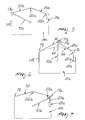
- the reference numeral 1 designates a device for covering and uncovering a body 2 that is part for example of a vehicle, not shown, such as a goods truck.
- the body 2 comprises two sides, such as a right side 3a and a left side 3b, which protrude from the lower region or bottom of the body 2.
- the sides 3a and 3b are advantageously mutually connected by a first rear wall or infilling 4a and by a second front wall or infilling 4b.
- the first and second walls 4a and 4b are preferably higher than the sides, and in the embodiment shown in the figures merely by way of example the walls 4a and 4b have an advantageously pentagonal shape, in which the upper vertices, designated by the reference numerals 5a and 5b in Figure 2, lie on the vertical plane that passes through the central axis that lies longitudinally to the bottom of the body 2.
- Figure 2 shows that two sides 6a and 6b for connection to respective lateral corners 7a and 7b extend from the vertex 5a of the wall 4a.
- the right lateral corner 7a delimits a first recess 8a, which is approximately L-shaped and forms a flat base for connection to a first lateral shoulder 9a of the first wall 4a.
- the second wall 4b is mirror-symmetrical with respect to the first wall 4a relative to a vertical plane that passes through the central transverse axis of the body 2, so as to form a second recess 8b.
- a first arm 10a and a second arm 10b are respectively pivoted at a central region of the first and second walls 4a and 4b along their central vertical axis or altitude and are preferably straight.
- the lengths of the first and second arms 10a and 10b are such that the first and second free ends of said arms, designated by the reference numerals 11a and 11b, lie respectively proximate to the recesses 8a and 8b.
- first and second free ends 11a and 11b are mutually connected by means of a straight rod 12, with which a first edge and a second edge, designated by the reference numerals 13a and 14a in Figure 8, of first and second covering canopies, designated by the reference numerals 13 and 14, are associated longitudinally.
- the first canopy 13 is adapted to cover the right lateral region of the body 2 and therefore has a width that is approximately equal to the height of the first shoulder 9a, so that it can reach the right side 3a once the rod 12 has been arranged at the flat base of the first shoulder 9a.
- the second canopy 14 which is larger than the first one, is adapted to cover the upper and lateral left region of the body 2, and therefore is approximately as wide as the pair of sides 6a and 6b plus the height of the second left shoulder, designated by the reference numeral 9b.
- the interconnection of the first and second canopies 13 and 14 to the rod 12 can be provided advantageously by means of the coupling of a strip 15a to the first and second edges 13a and 14a, the entire assembly being adapted to be inserted within a complementarily shaped slot 15b formed longitudinally within the rod 12 along the generating surface.
- the electric motor 16 comprises a body 16a, which is provided with an end portion 50 that protrudes outside the rod 12, so as to associate itself nonrotatably with the first free end 11a of the first arm 10a.
- the end part 50 of the body 16a is accommodated at least partially in a first hub 17a, which is arranged coaxially and is associated nonrotatably with the rod 12.
- At least the internal surface, for contact with the body 16a of the electric motor 16 is made of materials having a low friction coefficient and is thus made for example of the material known by the tradename Teflon, so as to allow the free rotation of the first hub 17a with respect to the motor 16.
- a coaxial driving shaft 16b protrudes from the body 16a and is associated nonrotatably with the rod 12: the nonrotatable interconnection between the driving shaft 16b and the rod 12 can be achieved advantageously by interposing a disk-like element 51, which is monolithically coupled to the driving shaft 16b and is shaped approximately complementarily to the internal profile of the rod 12, as shown in Figure 8.
- the disk-like element 51 has a recess 51a that is shaped approximately complementarily to the slot 15b, so as to constitute a means for transmitting the rotation of the driving shaft 16b to the rod 12.
- the rod 12 is associated with a second hub, designated by the reference numeral 17b in Figure 14, which accommodates a bearing 18 that is adapted for the rotary interconnection of the second free end 11b of the second arm 10b.
- an activation of the electric motor 16 according to a counterclockwise rotation of the driving shaft 16b produces a counterclockwise rotation of the rod 12, so as to roll up at least one first portion of the second canopy 14.
- connection of the second canopy 14 to the left side 3b provided advantageously by way of snap-acting hooks and therefore without elastically deformable means such as elastic cords or cables, forces the movement of the first arm 10a, along a circular arc-like path from the corner 7a toward the corner 7b, simultaneously with the rotational movement of the rod 12.
- the second arm 10b is guided by the rod 12 along a rotation that is fully similar to the rotation of the first arm 10a, so as to ensure effective support of the rod 12.
- the rotary motion of the rod 12 with respect to the first and second arms 10a and 10b is allowed by the free rotation of the first hub 17a with respect to the body 16a of the electric motor 16 and by the presence of the bearing 18.
- the first and second hubs 17a and 17b comprise a first pulley and a second pulley, designated by the reference numerals 19a and 19b respectively, which interact with means for controlling the rotation of the rod 12 and for retracting it.
- Guiding elements 22a and 22b can be arranged advantageously along the path of the first and second belts 20a and 20b and are preferably constituted for example by pairs of wheels that are freely pivoted to the first and second walls 4a and 4b.
- first and second arms 10a and 10b during the operation for uncovering the body 2, move in contrast with the traction force applied by the tensioning devices 21a and 21b: this ensures that the second canopy 14 is always taut during rolling-up.
- the first canopy 13 rolls up, opening the interspace arranged above the right side 3a, and part of the second canopy 14 also rolls up.
- the first and second arms 10a and 10b then descend until they reach the position of Figure 3, in which the end portion, designated by the reference numeral 14b, of the second canopy 14 is still unrolled.
- the covering operation is achieved by means of an activation of the electric motor 16 according to a clockwise rotation of the driving shaft 16b, so as to force the rigidly coupled rod 12 to perform an identical clockwise rotation.
- the clockwise movement of the arms 10a and 10b is allowed by the presence of the retraction means of the rod 12, which are constituted by the first and second belts 20a and 20b.
- the pulleys 17a and 17b associated with the rod 12 in fact retract the first and second belts 20a and 20b.
- the first canopy 13 remains in a raised position, as shown in Figure 4; it can be repositioned manually, for example by activating a cord or another grip means, which is associated with the first canopy 13 at one end.
- the operator To unroll the second canopy 14, the operator must activate the motor 16 with a rotation that is the opposite of the preceding one and wait for the rod to arrange its ends at the first and second recesses 8a and 8b.
- the invention has achieved the intended aim and objects, a device for covering and uncovering the body of a vehicle having been provided which can be activated rapidly and very easily even by a single operator.
- the invention allows to access the goods contained in the body from both sides, since it allows easy and complete removal of the first and second covering canopies.
- the covering and uncovering device is very sturdy and, in view of its constructive simplicity, is scarcely subject to malfunctions or breakdowns.
- connection of the second canopy 14 to the left side 3b by way of mechanical means that are substantially not elastically deformable, such as for example closure levers or snap-acting hooks, allows to avoid the need for the presence of means for temporary interconnection between the canopy and the body, such as said pin.
- a clockwise rotation of the driving shaft entails a counterclockwise rotation of the rod and a consequent counterclockwise movement of the first and second arms.
- the means for controlling the rotation of the rod and for returning it can be constituted not only by one or two belts but, as an alternative, by an inextensible cable or cords, chains or other mechanical means that are adapted to transmit a force and to be retracted and/or returned within mechanical elements such as for example said pulleys.
Landscapes
- Engineering & Computer Science (AREA)
- Mechanical Engineering (AREA)
- Power-Operated Mechanisms For Wings (AREA)
Applications Claiming Priority (2)
| Application Number | Priority Date | Filing Date | Title |
|---|---|---|---|
| ITTV20020115 | 2002-10-14 | ||
| ITTV20020115 ITTV20020115A1 (it) | 2002-10-14 | 2002-10-14 | Struttura di dispositivo per la copertura e la scopertura |
Publications (1)
| Publication Number | Publication Date |
|---|---|
| EP1410934A1 true EP1410934A1 (fr) | 2004-04-21 |
Family
ID=32040286
Family Applications (1)
| Application Number | Title | Priority Date | Filing Date |
|---|---|---|---|
| EP03020583A Withdrawn EP1410934A1 (fr) | 2002-10-14 | 2003-09-18 | Système de bâchage/débâchage, notamment pour un véhicule de fret |
Country Status (2)
| Country | Link |
|---|---|
| EP (1) | EP1410934A1 (fr) |
| IT (1) | ITTV20020115A1 (fr) |
Citations (7)
| Publication number | Priority date | Publication date | Assignee | Title |
|---|---|---|---|---|
| US3885255A (en) * | 1973-09-13 | 1975-05-27 | Oberschwaeb Metallwaren | Covering arrangement for swimming pools |
| US4529098A (en) * | 1984-07-12 | 1985-07-16 | Heider Merle J | Top closure for a rectangular box |
| US5002328A (en) * | 1989-06-06 | 1991-03-26 | Walter Michel | Drive system for flexible cover |
| EP0427677A1 (fr) * | 1989-11-08 | 1991-05-15 | Bieri Blachen Ag | Bâche roulable |
| US5549347A (en) * | 1993-07-16 | 1996-08-27 | Willknight, Inc. | All weather mechanically reciprocatable roll top cover apparatus |
| WO1998024656A1 (fr) * | 1996-12-02 | 1998-06-11 | Magnus Pettersson | Dispositif destine a couvrir des compartiments a marchandises |
| GB2368880A (en) * | 2000-11-07 | 2002-05-15 | Transcover Engineering Ltd | Cover with roller means for vehicle loads |
-
2002
- 2002-10-14 IT ITTV20020115 patent/ITTV20020115A1/it unknown
-
2003
- 2003-09-18 EP EP03020583A patent/EP1410934A1/fr not_active Withdrawn
Patent Citations (7)
| Publication number | Priority date | Publication date | Assignee | Title |
|---|---|---|---|---|
| US3885255A (en) * | 1973-09-13 | 1975-05-27 | Oberschwaeb Metallwaren | Covering arrangement for swimming pools |
| US4529098A (en) * | 1984-07-12 | 1985-07-16 | Heider Merle J | Top closure for a rectangular box |
| US5002328A (en) * | 1989-06-06 | 1991-03-26 | Walter Michel | Drive system for flexible cover |
| EP0427677A1 (fr) * | 1989-11-08 | 1991-05-15 | Bieri Blachen Ag | Bâche roulable |
| US5549347A (en) * | 1993-07-16 | 1996-08-27 | Willknight, Inc. | All weather mechanically reciprocatable roll top cover apparatus |
| WO1998024656A1 (fr) * | 1996-12-02 | 1998-06-11 | Magnus Pettersson | Dispositif destine a couvrir des compartiments a marchandises |
| GB2368880A (en) * | 2000-11-07 | 2002-05-15 | Transcover Engineering Ltd | Cover with roller means for vehicle loads |
Also Published As
| Publication number | Publication date |
|---|---|
| ITTV20020115A1 (it) | 2004-04-15 |
Similar Documents
| Publication | Publication Date | Title |
|---|---|---|
| US5404926A (en) | Roller shade for non-rectangular openings | |
| KR101950588B1 (ko) | 창문 차양 | |
| US5799715A (en) | Liftable window covering with multiple lifting cords and a single pull cord | |
| US7896058B2 (en) | Side window roller blind with hinged pull rod and rectangular support rod | |
| KR20080083593A (ko) | 차량용 선스크린 블라인드 | |
| JP2003041873A (ja) | ローラブラインド | |
| KR101383009B1 (ko) | 롤러형 바를 이용한 롤 블라인드 장치 | |
| US20100219656A1 (en) | Cabling arrangement for tarping systems | |
| US4234224A (en) | Truck box cover device | |
| JP2004003323A (ja) | 日よけ、特にサンルーム用日よけ、及び日よけ布の繰り出しを制御するための方法 | |
| KR20200142016A (ko) | 차양 및 그에 따른 스프링 구동 시스템 | |
| KR102543607B1 (ko) | 보호 덮개 시스템을 구비한 차량 | |
| KR20180019222A (ko) | 차량의 2 부분 측면 윈도우 구성을 위한 차양 장치 | |
| EP1410934A1 (fr) | Système de bâchage/débâchage, notamment pour un véhicule de fret | |
| CA1060927A (fr) | Couvercle pour caisse de camion | |
| CN222987954U (zh) | 遮阳帘的驱动结构和遮阳结构、车辆 | |
| EP0935048B1 (fr) | Couverture de fenêtre double avec un seul dispositif de commande | |
| CN112682940B (zh) | 卷帘机构及空调器 | |
| CN218536507U (zh) | 侧翻自动篷布机 | |
| JP2002225567A (ja) | 自動車ドアの雨覆い装置 | |
| CN215361122U (zh) | 一种车用智能伸缩软顶货厢 | |
| JPH09315145A (ja) | 車両用ブラインド装置 | |
| US9126471B2 (en) | Rolling tarpaulin system for selectively covering and uncovering trailers for trucks | |
| WO2021040522A1 (fr) | Système d'auvent pour véhicule de loisirs | |
| KR100423826B1 (ko) | 자동차의 윈도우 글래스 승강장치 |
Legal Events
| Date | Code | Title | Description |
|---|---|---|---|
| PUAI | Public reference made under article 153(3) epc to a published international application that has entered the european phase |
Free format text: ORIGINAL CODE: 0009012 |
|
| AK | Designated contracting states |
Kind code of ref document: A1 Designated state(s): AT BE BG CH CY CZ DE DK EE ES FI FR GB GR HU IE IT LI LU MC NL PT RO SE SI SK TR |
|
| AX | Request for extension of the european patent |
Extension state: AL LT LV MK |
|
| STAA | Information on the status of an ep patent application or granted ep patent |
Free format text: STATUS: THE APPLICATION HAS BEEN WITHDRAWN |
|
| AKX | Designation fees paid | ||
| REG | Reference to a national code |
Ref country code: DE Ref legal event code: 8566 |
|
| 18W | Application withdrawn |
Effective date: 20041228 |