EP1410949A2 - Dispositif d'éclairage pour véhicule automobile - Google Patents
Dispositif d'éclairage pour véhicule automobile Download PDFInfo
- Publication number
- EP1410949A2 EP1410949A2 EP03022737A EP03022737A EP1410949A2 EP 1410949 A2 EP1410949 A2 EP 1410949A2 EP 03022737 A EP03022737 A EP 03022737A EP 03022737 A EP03022737 A EP 03022737A EP 1410949 A2 EP1410949 A2 EP 1410949A2
- Authority
- EP
- European Patent Office
- Prior art keywords
- diodes
- light
- diode
- operated
- photodiode
- Prior art date
- Legal status (The legal status is an assumption and is not a legal conclusion. Google has not performed a legal analysis and makes no representation as to the accuracy of the status listed.)
- Withdrawn
Links
Images
Classifications
-
- B—PERFORMING OPERATIONS; TRANSPORTING
- B60—VEHICLES IN GENERAL
- B60Q—ARRANGEMENT OF SIGNALLING OR LIGHTING DEVICES, THE MOUNTING OR SUPPORTING THEREOF OR CIRCUITS THEREFOR, FOR VEHICLES IN GENERAL
- B60Q11/00—Arrangement of monitoring devices for devices provided for in groups B60Q1/00 - B60Q9/00
- B60Q11/005—Arrangement of monitoring devices for devices provided for in groups B60Q1/00 - B60Q9/00 for lighting devices, e.g. indicating if lamps are burning or not
-
- B—PERFORMING OPERATIONS; TRANSPORTING
- B60—VEHICLES IN GENERAL
- B60Q—ARRANGEMENT OF SIGNALLING OR LIGHTING DEVICES, THE MOUNTING OR SUPPORTING THEREOF OR CIRCUITS THEREFOR, FOR VEHICLES IN GENERAL
- B60Q1/00—Arrangement of optical signalling or lighting devices, the mounting or supporting thereof or circuits therefor
- B60Q1/26—Arrangement of optical signalling or lighting devices, the mounting or supporting thereof or circuits therefor the devices being primarily intended to indicate the vehicle, or parts thereof, or to give signals, to other traffic
- B60Q1/2696—Mounting of devices using LEDs
-
- H—ELECTRICITY
- H05—ELECTRIC TECHNIQUES NOT OTHERWISE PROVIDED FOR
- H05B—ELECTRIC HEATING; ELECTRIC LIGHT SOURCES NOT OTHERWISE PROVIDED FOR; CIRCUIT ARRANGEMENTS FOR ELECTRIC LIGHT SOURCES, IN GENERAL
- H05B45/00—Circuit arrangements for operating light-emitting diodes [LED]
- H05B45/50—Circuit arrangements for operating light-emitting diodes [LED] responsive to malfunctions or undesirable behaviour of LEDs; responsive to LED life; Protective circuits
- H05B45/58—Circuit arrangements for operating light-emitting diodes [LED] responsive to malfunctions or undesirable behaviour of LEDs; responsive to LED life; Protective circuits involving end of life detection of LEDs
-
- H—ELECTRICITY
- H05—ELECTRIC TECHNIQUES NOT OTHERWISE PROVIDED FOR
- H05B—ELECTRIC HEATING; ELECTRIC LIGHT SOURCES NOT OTHERWISE PROVIDED FOR; CIRCUIT ARRANGEMENTS FOR ELECTRIC LIGHT SOURCES, IN GENERAL
- H05B47/00—Circuit arrangements for operating light sources in general, i.e. where the type of light source is not relevant
- H05B47/20—Responsive to malfunctions or to light source life; for protection
Definitions
- the invention relates to a lighting device, in particular for Motor vehicles, with a diode arrangement comprising several light-emitting diodes. It also relates to a method for operating and / or monitoring such a lighting device.
- the invention is therefore based on the object of an improved lighting device as well as an improved process of the beginning Specify the type mentioned, with the simplest and most economical In particular, reliable monitoring of the LED arrangement is guaranteed.
- an illumination device especially for motor vehicles, with one or more light emitting diodes comprising diode arrangement, a diffuser or the like, which partially transmits the light emitted by the LED arrangement and partially reflected back to the LED array, and a control and / or evaluation unit assigned to the LED arrangement, through which the diodes of the LED arrangement can be controlled are that a respective diode alternately as a light emitting diode and is operated as a photodiode, with at least in each phase a diode as a light-emitting diode and at least one diode as a photodiode is operated, and wherein the output signal of a respective one as a photodiode operated diode of the control and / or evaluation unit for evaluation is fed.
- LED Light emitting diode
- Illuminating devices are adjacent diodes of the light-emitting diode arrangement alternately controlled in opposite directions, so that of the concerned Diodes each have at least one as a light emitting diode and at least one one is operated as a photodiode. In such an alternating opposite flickering is avoided, it being ensured that at least one diode is always used as the photodiode Available.
- the control and / or evaluation unit is advantageously used based on the output signals of the diodes operated as a photodiode respective light distribution and / or a possible failure of individual diodes detected within the LED array.
- control and / or evaluation unit can be used based on the output signals of the diodes operated as a photodiode especially the luminosity and thus possible aging individual diodes are detected within the light-emitting diode arrangement.
- control and / or evaluation unit supplies the lighting device after detection of an error occurring in the LED arrangement such as in particular a diode failure, a drop in luminance and / or the like an error signal.
- the output signals of the diodes operated as a photodiode are more conveniently tapped via a multiplexer.
- the output signals of the diodes operated as a photodiode can their evaluation are fed to an amplifier.
- a driver is expediently used to control the light-emitting diodes intended.
- the inputs of the multiplexer can be connected to the outputs of the Driver connected.
- the amplifier, the multiplexer and / or the driver can control and / or Evaluation unit must be assigned.
- LEDs connected in series and the diode series connections so controllable that their diodes alternately as LEDs and as Photodiodes are operated, with at least one in each phase Diode series connection for operating the associated diodes as Light emitting diodes and at least one diode series connection for one Operation of the associated diodes is controlled as photodiodes.
- Adjacent diode rows and / or columns are advantageously the LED arrangement alternately controllable in opposite directions, so that at least one of each of the relevant diode rows or columns for operating the associated diodes as LEDs and at least one driven for operation of the associated diodes as photodiodes is.
- the diodes of a respective diode row or - Column in particular be connected in series.
- the object specified above is also achieved through a method of operating and / or monitoring a particular lighting device intended for motor vehicles with a Diode arrangement comprising several light-emitting diodes, in which one Diffuser or the like is used, that of the light emitting diode arrangement partially emits light and partly to Light-emitting diode arrangement reflected back, a respective diode alternately is operated as a light-emitting diode and as a photodiode, in each Phase at least one diode as a light emitting diode and at least one Diode is operated as a photodiode, and the output signal of each as a diode operated diode is evaluated accordingly.
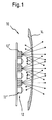
- FIG. 1 and 2 is a schematic illustration of an example Embodiment of a lighting device 10 shown.
- Such Lighting device 10 can be used in particular in motor vehicles become. This can be a turn signal, for example and / or act like. Basically, however, there are others Possible types of use.
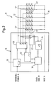
- FIG. 1 shows the lighting device 10 in a schematic side view shown. A simplified circuit diagram of this lighting device 10 is shown in FIG. 2.
- the lighting device comprises 10 a light-emitting diode arrangement 12 and a diffusing screen 14 or the like, which emitted from the light emitting diode arrangement 12 Partially transmits light and partly to light-emitting diode arrangement 12 reflected back.
- the lighting device 10 also includes one of the light emitting diode arrangement 12 assigned electronic control and / or evaluation unit 18.
- the diodes are by this control and / or evaluation unit 18 12 'of the light-emitting diode arrangement 12 can be controlled such that a respective one Diode 12 'is operated alternately as a light emitting diode and as a photodiode.
- At least one diode is used in each drive phase Light-emitting diode and at least one diode operated as a photodiode.
- the Output signal of a respective diode 12 'operated as a photodiode is fed to the control and / or evaluation unit for evaluation.
- neighboring ones can Diodes 12 'of the light-emitting diode arrangement 12 alternately in opposite directions or alternately controlled, so that of the concerned Diodes each have at least one as a light emitting diode and at least one as Photodiode is operated.
- the Light emitted by the hatched diodes 12 ' is emitted by the lens 14 partly to the light emitting diode arrangement 12 and thus also to the non-hatched diodes 12 'currently operated as photodiodes reflected back. Their output signals can thus be used to diagnose the State of the LED arrangement 12 evaluated accordingly become.
- the output signals can be used of the diodes each operated as a photodiode, for example the respective light distribution and / or a possible failure of individual Diodes 12 'are detected within the light-emitting diode arrangement 12.
- the control and / or evaluation unit can be used 18 based on the output signals of each operated as a photodiode Diodes 12 ', for example, also the luminosity and thus one possible aging of individual diodes 12 'within the light emitting diode arrangement 12 are recorded.
- the control and / or evaluation unit 18 can in particular do so be designed so that after detection of one in the light emitting diode arrangement 12 errors that occur, in particular a diode failure, of a drop in luminance and / or the like provides an error signal 20.
- the output signals of the Diodes 12 ' operated as a photodiode in the present exemplary embodiment tapped via a multiplexer 22.
- the output signals of the diodes 12 'described as a photodiode can are fed to an amplifier 24 before they are evaluated.
- a driver 26 is provided to control the diodes 12 '.
- the inputs of the multiplexer are 22 connected to the outputs of the driver 26.
- the amplifier 24, the multiplexer 22 and the Driver 26 assigned to the control and / or evaluation unit 18, i.e. part this control and / or evaluation unit 18.
- the control and / or evaluation unit 18 also includes a current sensor 28, a control module 30 and a driver 26, the multiplexer 22 and the control module 30 acting clock generator 32.
- An output of the current sensor 28 and an output of the Amplifier 24 is connected to the control module 30.
- the current sensor 28 is in the input area of a voltage supply 34 connected control and / or evaluation unit 18 is provided.
- the Control module 30 supplies error signal 20 when a fault is detected.
- the diode arrangement 12 is on the one hand connected to the outputs of the driver 26 and on the other hand connected to ground 36.
- each case several light emitting diodes 12 'connected in series.
- the Diode series circuits 12 are via the control and / or evaluation unit 18 controllable so that their diodes 12 'alternately as LEDs and operated as photodiodes.
- There is in everyone Control phase each have at least one diode series circuit 12 "for an operation of the associated diodes 12 'as light emitting diodes and at least a diode series circuit 12 "for operation of the associated Diodes 12 'driven as photodiodes.
- adjacent diode rows and / or columns can be used the LED arrangement 12 alternately in opposite directions or alternating phases can be controlled so that the relevant diode rows or columns each have at least one for operating the associated one Diodes 12 'as light emitting diodes and at least one for operation of the associated diodes 12 'is controlled as photodiodes.
- Such a lighting device 10 enables not only the failure individual light emitting diodes 12 'also the detection of a drop in luminance and thus the aging of individual light emitting diodes or LEDs 12 '. there the properties of the diodes 12 'are exploited so that they both can be operated as a light emitting diode as well as a photodiode.
- the diode arrays can in particular be constructed such that neighboring ones Diodes can be controlled in alternating phases, thereby a Flickering is avoided and always at least one diode as a photodiode is usable.
- the influence of sources of interference such as ambient light, temperature, Voltage fluctuations and contamination on the diagnostic system is due to the measuring method used here to a minimum reduced.
Landscapes
- Engineering & Computer Science (AREA)
- Mechanical Engineering (AREA)
- Circuit Arrangement For Electric Light Sources In General (AREA)
- Arrangement Of Elements, Cooling, Sealing, Or The Like Of Lighting Devices (AREA)
Applications Claiming Priority (2)
| Application Number | Priority Date | Filing Date | Title |
|---|---|---|---|
| DE10248238 | 2002-10-16 | ||
| DE10248238A DE10248238A1 (de) | 2002-10-16 | 2002-10-16 | Beleuchtungseinrichtung insbesondere für Kraftfahrzeuge |
Publications (1)
| Publication Number | Publication Date |
|---|---|
| EP1410949A2 true EP1410949A2 (fr) | 2004-04-21 |
Family
ID=32038723
Family Applications (1)
| Application Number | Title | Priority Date | Filing Date |
|---|---|---|---|
| EP03022737A Withdrawn EP1410949A2 (fr) | 2002-10-16 | 2003-10-09 | Dispositif d'éclairage pour véhicule automobile |
Country Status (2)
| Country | Link |
|---|---|
| EP (1) | EP1410949A2 (fr) |
| DE (1) | DE10248238A1 (fr) |
Cited By (7)
| Publication number | Priority date | Publication date | Assignee | Title |
|---|---|---|---|---|
| EP1779708A4 (fr) * | 2004-08-06 | 2010-08-18 | Koninkl Philips Electronics Nv | Systeme d'eclairage comprenant une emission et une detection photonique utilisant des elements electroluminescents |
| EP2050619A3 (fr) * | 2007-10-17 | 2010-09-22 | Audi AG | Dispositif et procédé d'émission d'un paramètre de fonctionnement d'au moins un moyen d'éclairage d'une source lumineuse d'un véhicule automobile |
| GB2488230A (en) * | 2011-02-18 | 2012-08-22 | Gm Global Tech Operations Inc | LED lighting device for a vehicle having photodiodes to detect LED failure |
| WO2014016103A1 (fr) * | 2012-07-25 | 2014-01-30 | Dräger Medical GmbH | Procédé et dispositif pour la détection de signaux optiques |
| CN104114412A (zh) * | 2012-02-07 | 2014-10-22 | 戴姆勒股份公司 | 机动车的照明装置 |
| EP3181459A1 (fr) * | 2015-12-17 | 2017-06-21 | Goodrich Lighting Systems GmbH | Unité d'éclairage extérieur d'aéronef et aéronef comprenant celle-ci |
| AT518887A5 (de) * | 2009-04-29 | 2018-02-15 | Tridonic Gmbh & Co Kg | Vorrichtung zum betreiben von leds |
Families Citing this family (5)
| Publication number | Priority date | Publication date | Assignee | Title |
|---|---|---|---|---|
| DE102007045259A1 (de) | 2007-09-21 | 2009-04-02 | Continental Automotive Gmbh | Verfahren und Vorrichtung zur Erfassung der von einer LED-Lichtquelle abgestrahlten Lichtleistung |
| DE102008025530B4 (de) * | 2008-05-28 | 2012-11-22 | Audi Ag | Einrichtung zur Prüfung der Funktion einer Leuchteinrichtung eines Kraftfahrzeugs |
| EP2579682B1 (fr) | 2011-10-07 | 2015-09-09 | Goodrich Lighting Systems GmbH | Procédé de contrôle d'un phare d'avion |
| DE102012004916A1 (de) | 2012-03-09 | 2012-09-20 | Daimler Ag | Beleuchtungseinrichtung für ein Kraftfahrzeug |
| DE102012008930A1 (de) | 2012-05-04 | 2012-12-06 | Daimler Ag | Leuchte und Vorrichtung zur Überwachung einer Funktion von Lichtquellen |
Family Cites Families (5)
| Publication number | Priority date | Publication date | Assignee | Title |
|---|---|---|---|---|
| DE4010627A1 (de) * | 1990-04-03 | 1990-08-23 | Gistl Egmont | Einrichtung zur gleichzeitigen funktionsueberwachung von mehreren gluehlampen mit einer fotozelle |
| DE19654853A1 (de) * | 1996-05-23 | 1997-11-27 | Ziegler Horst | Steuerschaltung zur Registrierung der Betätigung einer optischen Taste |
| US6153985A (en) * | 1999-07-09 | 2000-11-28 | Dialight Corporation | LED driving circuitry with light intensity feedback to control output light intensity of an LED |
| DE10018760A1 (de) * | 2000-04-15 | 2001-10-18 | Volkswagen Ag | Schaltung zur Überwachung der Funktion einer Leuchtdiode |
| DE10239449B4 (de) * | 2002-02-06 | 2013-10-24 | Ulrich Kuipers | Verfahren und Vorrichtung zur Realisierung von LED-Leuchten mit Farb- und Helligkeitseinstellung und dem dazugehörigen Bedienelement |
-
2002
- 2002-10-16 DE DE10248238A patent/DE10248238A1/de not_active Withdrawn
-
2003
- 2003-10-09 EP EP03022737A patent/EP1410949A2/fr not_active Withdrawn
Cited By (12)
| Publication number | Priority date | Publication date | Assignee | Title |
|---|---|---|---|---|
| EP1779708A4 (fr) * | 2004-08-06 | 2010-08-18 | Koninkl Philips Electronics Nv | Systeme d'eclairage comprenant une emission et une detection photonique utilisant des elements electroluminescents |
| EP2050619A3 (fr) * | 2007-10-17 | 2010-09-22 | Audi AG | Dispositif et procédé d'émission d'un paramètre de fonctionnement d'au moins un moyen d'éclairage d'une source lumineuse d'un véhicule automobile |
| AT518887A5 (de) * | 2009-04-29 | 2018-02-15 | Tridonic Gmbh & Co Kg | Vorrichtung zum betreiben von leds |
| AT518887B1 (de) * | 2009-04-29 | 2018-02-15 | Tridonic Gmbh & Co Kg | Vorrichtung zum betreiben von leds |
| GB2488230A (en) * | 2011-02-18 | 2012-08-22 | Gm Global Tech Operations Inc | LED lighting device for a vehicle having photodiodes to detect LED failure |
| DE102011011699A1 (de) * | 2011-02-18 | 2012-08-23 | GM Global Technology Operations LLC (n. d. Gesetzen des Staates Delaware) | Beleuchtungseinrichtung für Fahrzeuge |
| US8786190B2 (en) | 2011-02-18 | 2014-07-22 | GM Global Technology Operations LLC | Lighting device for vehicles |
| CN104114412A (zh) * | 2012-02-07 | 2014-10-22 | 戴姆勒股份公司 | 机动车的照明装置 |
| WO2014016103A1 (fr) * | 2012-07-25 | 2014-01-30 | Dräger Medical GmbH | Procédé et dispositif pour la détection de signaux optiques |
| US9559781B2 (en) | 2012-07-25 | 2017-01-31 | Drägerwerk AG & Co. KGaA | Process for the detection of optical signals |
| EP3181459A1 (fr) * | 2015-12-17 | 2017-06-21 | Goodrich Lighting Systems GmbH | Unité d'éclairage extérieur d'aéronef et aéronef comprenant celle-ci |
| US10362657B2 (en) | 2015-12-17 | 2019-07-23 | Goodrich Lighting Systems Gmbh | Exterior aircraft light unit and aircraft comprising the same |
Also Published As
| Publication number | Publication date |
|---|---|
| DE10248238A1 (de) | 2004-04-29 |
Similar Documents
| Publication | Publication Date | Title |
|---|---|---|
| DE102008047731B4 (de) | Verfahren zur Fehlererkennung in einer Beleuchtungsvorrichtung | |
| EP1410949A2 (fr) | Dispositif d'éclairage pour véhicule automobile | |
| DE102013210261B4 (de) | Beleuchtungsvorrichtung für ein Fahrzeug | |
| DE102016109296B4 (de) | Ansteuern mehrerer Lichtquellen | |
| EP2247161B1 (fr) | Reconnaissance d'une panne pour moyen d'éclairage dans des lampes de véhicules automobiles | |
| DE102012224323B4 (de) | Verfahren und Einrichtung zur Funktionsprüfung von Leuchtmitteln | |
| DE69829169T2 (de) | Vielfach-optischen-Weg Lichtschalter. | |
| DE10103611B4 (de) | Schaltungsanordnung zum Betreiben von mehreren Leuchtmitteln | |
| DE102013001274A1 (de) | Verfahren zur Steuerung mehrerer unabhängig voneinander aktivierbarer Dioden in einem Scheinwerfer | |
| DE69231311T2 (de) | Optoelektronische Schranke | |
| DE10227487A1 (de) | Beleuchtungsvorrichtung | |
| DE102015219901B4 (de) | Diagnosevorrichtung und Verfahren zum Detektieren eines Defekts von zumindest einer aus mehreren Leuchtdioden | |
| WO2017136864A1 (fr) | Procédé et dispositif ict de contrôle de modules d'un dispositif d'éclairage qui contiennent au moins deux led | |
| DE10131824A1 (de) | Schaltungseinrichtung für die Ausfallerkennung von Leuchtdioden in einem Kraftfahrzeug | |
| DE102017200895A1 (de) | Verfahren und Vorrichtung zum Überprüfen eines Anzeigegeräts für ein Fahrzeug und Anzeigegerät für ein Fahrzeug | |
| DE112021006053T5 (de) | Treibervorrichtung für ein lichtemittierendes element | |
| DE102018201102A1 (de) | Verfahren und vorrichtung zum funktionsprüfen einer matrix-lichtquellenanordnung und scheinwerfer damit | |
| EP1903836A1 (fr) | Agencement de commutation destiné à la surveillance du courant de charge du dispositif d'éclairage d'un véhicule automobile | |
| EP3528005A1 (fr) | Dispositif de caméra tof destiné à la détection d'erreurs | |
| DE102012002334A1 (de) | Beleuchtungseinrichtung eines Kraftfahrzeugs | |
| DE60302434T2 (de) | Erkennung von Anhängeranwesenheit und -typ durch Stromdetektion | |
| DE60209677T2 (de) | Lichtinformationseinrichtung zum Anzeigen des Betriebszustandes eines Systems, insbesondere für die Avionics | |
| DE102009042619B3 (de) | Anzeigevorrichtung | |
| DE10143792B4 (de) | Fahrzeugrückleuchte | |
| EP2390678B1 (fr) | Reconnaissance de panne dans des consommateurs couplés en parallèle |
Legal Events
| Date | Code | Title | Description |
|---|---|---|---|
| PUAI | Public reference made under article 153(3) epc to a published international application that has entered the european phase |
Free format text: ORIGINAL CODE: 0009012 |
|
| AK | Designated contracting states |
Kind code of ref document: A2 Designated state(s): AT BE BG CH CY CZ DE DK EE ES FI FR GB GR HU IE IT LI LU MC NL PT RO SE SI SK TR |
|
| AX | Request for extension of the european patent |
Extension state: AL LT LV MK |
|
| STAA | Information on the status of an ep patent application or granted ep patent |
Free format text: STATUS: THE APPLICATION IS DEEMED TO BE WITHDRAWN |
|
| 18D | Application deemed to be withdrawn |
Effective date: 20090501 |