EP1411019A1 - Dispositif de manuntention pour le levage avec basculement d'objets - Google Patents
Dispositif de manuntention pour le levage avec basculement d'objets Download PDFInfo
- Publication number
- EP1411019A1 EP1411019A1 EP03292580A EP03292580A EP1411019A1 EP 1411019 A1 EP1411019 A1 EP 1411019A1 EP 03292580 A EP03292580 A EP 03292580A EP 03292580 A EP03292580 A EP 03292580A EP 1411019 A1 EP1411019 A1 EP 1411019A1
- Authority
- EP
- European Patent Office
- Prior art keywords
- sling
- hook
- lifting
- suspended
- link chain
- Prior art date
- Legal status (The legal status is an assumption and is not a legal conclusion. Google has not performed a legal analysis and makes no representation as to the accuracy of the status listed.)
- Withdrawn
Links
Images



Classifications
-
- B—PERFORMING OPERATIONS; TRANSPORTING
- B66—HOISTING; LIFTING; HAULING
- B66C—CRANES; LOAD-ENGAGING ELEMENTS OR DEVICES FOR CRANES, CAPSTANS, WINCHES, OR TACKLES
- B66C1/00—Load-engaging elements or devices attached to lifting or lowering gear of cranes or adapted for connection therewith for transmitting lifting forces to articles or groups of articles
- B66C1/10—Load-engaging elements or devices attached to lifting or lowering gear of cranes or adapted for connection therewith for transmitting lifting forces to articles or groups of articles by mechanical means
- B66C1/12—Slings comprising chains, wires, ropes, or bands; Nets
- B66C1/125—Chain-type slings
-
- B—PERFORMING OPERATIONS; TRANSPORTING
- B66—HOISTING; LIFTING; HAULING
- B66C—CRANES; LOAD-ENGAGING ELEMENTS OR DEVICES FOR CRANES, CAPSTANS, WINCHES, OR TACKLES
- B66C1/00—Load-engaging elements or devices attached to lifting or lowering gear of cranes or adapted for connection therewith for transmitting lifting forces to articles or groups of articles
- B66C1/10—Load-engaging elements or devices attached to lifting or lowering gear of cranes or adapted for connection therewith for transmitting lifting forces to articles or groups of articles by mechanical means
- B66C1/12—Slings comprising chains, wires, ropes, or bands; Nets
- B66C1/14—Slings with hooks
Definitions
- the present invention relates to a handling device for lifting with tilting objects. It applies more particularly, but not exclusively, to reels of strips.
- the strips are very thin metal strips, the packaging of which is in particular in the form of coils. Their lifting and handling, in particular to return them from a horizontal position (placed on one side) to a vertical position (for example with a view to their engagement on a mandrel), prove to be difficult due to their relatively large weight and the fineness of the coiled bands.
- This operation is generally carried out by means of a sling engaging through the central orifice of the coil so as to pass around a section of this coil.
- the sling When the sling is pulled to lift a spool, it causes the spool to tip over from its horizontal position to a vertical position. During this tilting, the sling slides on the reel, exerting at its periphery, and in particular at its angular regions, intense friction. This friction is likely to cause significant damage to the spool and the sling.
- the invention aims to resolve these drawbacks.
- a lifting device involving a sling forming a base intended to come at least partially surround the object to lifting and lifting means of the sling, these lifting means comprising a rotating support piece on which the sling therein suspended can slide so that the frictional forces dynamics generated by this sliding are lower than the forces of static friction exerted between the sling and the object to be lifted.
- the lifting means may include a lifting gear hook as well a block (pulley rotatably mounted on a yoke) suspended from the hook and through which the sling passes.
- the sling may be directly suspended from the hook of the lifting device.
- this hook may include, in its lower part, a rotating roller on which the sling is suspended.
- It may also include disengageable and / or locking means load break of the rotational movements of the roller and / or the means of braking, possibly adjustable, of the rotation of the roller.
- the hook can be pivotally mounted around an axis perpendicular to the axis of the pulley thanks to a swivel secured to the cable the lifting gear.
- the sling can form a loop and be made in several sections detachable. It may include stop means cooperating with the rotating support piece to limit its sliding in one direction or in the other.
- the device according to the invention involves a sling 1 and lifting means 2 of said sling.
- a swivel hook 8 is fixed on the other shackle 4 'by means of a ring 9 and this hook 8 is passed through the second ring 7' of the flat link chain 5.
- the swivel allows the hook to orient itself according to the position of the sling 1 around the coils.
- Each of the shackles is closed by means of a pin 10 and a nut 11.
- the flat link chain 5 and, consequently, the protective sheath 6, may be wider than the link chain 3 so as to increase the bearing surface of the sling on the reels and thus avoid any deterioration of these.
- the lifting means 2 comprise a hook 12 of a lifting device (not shown) as well as a block 13 (pulley 14 rotatably mounted on a yoke 15) suspended from the hook 12 by means of a ring 16 and by which passes sling 1.
- the pulley 14 is rotatably mounted around an axis 17 passing through the two cheeks of the yoke 15 and which includes a head 18 at one end and a nut 19 at the other end.
- Shackles 4, 4 ' are dimensioned so as to act as stop means bearing on the yoke 15 to limit the sliding of the chain to links 3 in one direction or the other.
- hooks 8, 12 used in this example include respectively a latch 20, 20 'which prevents the rings 9, 16 from coming out.
- the device according to the invention is used in the following manner: The reels being stored flat, the sling 1 is passed around a section of a strip reel B. (Figure 2a).
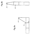
- the points P and P ' make it possible to identify the position of the sling 1 relative to the reel B (for the point P) and to the pulley 14 (for the point P'). It can be seen that the sling remains stationary relative to said reel (the point P retains its position) but that it slides on the pulley by rotating it in the direction of the arrow F (the point P 'moves) (Figure 2b).
- a pulley 21 is integrated in the part lower curved hook so that its axis of rotation is horizontally aligned.
- the axis of rotation 22 of the pulley 23 is not integrated in the hook but fixed horizontally at the level from its ends, on either side of the curved end of the hook.
- pulley can be replaced by a simple mounted tube rotary.
Landscapes
- Engineering & Computer Science (AREA)
- Mechanical Engineering (AREA)
- Load-Engaging Elements For Cranes (AREA)
Abstract
Description
Leur levage et leur manutention, notamment pour les retourner d'une position horizontale (posées sur une face) à une position verticale (par exemple en vue de leur engagement sur un mandrin), s'avèrent délicats du fait de leur poids relativement important et de la finesse des bandes enroulées. Cette manoeuvre est généralement réalisée au moyen d'une élingue s'engageant par l'orifice central de la bobine de manière à passer autour d'une section de cette bobine. Lorsque l'élingue est tirée pour soulever une bobine, elle provoque un basculement de la bobine qui passe de sa position horizontale à une position verticale. Au cours de ce basculement, l'élingue coulisse sur la bobine en exerçant à sa périphérie, et en particulier au niveau de ses régions angulaires, des frottements intenses. Ces frottements sont susceptibles de provoquer des détériorations notables de la bobine et de l'élingue.
- une chaíne à maillons, ou,
- une chaíne à maillons plats, ou,
- une élingue souple, par exemple en matière textile, ou,
- une combinaison de ces différents types d'élingue.
Dans ce cas, ce crochet pourra comprendre, dans sa partie inférieure, un galet rotatif sur lequel l'élingue se trouve suspendue.
- une chaíne à maillons 3 terminée à ses extrémités par deux manilles 4, 4',
- une chaíne à maillons plats 5 passant à l'intérieur d'une gaine de protection 6 en matière textile et terminée à ses extrémités par deux anneaux 7, 7', l'anneau 7 étant attaché sur la manille 4.
L'émerillon permet au crochet de s'orienter en fonction de la position de l'élingue 1 autour des bobines.
Les bobines étant stockées à plat, l'élingue 1 est passée autour d'une section d'une bobine de feuillards B. (Figure 2a). Les points P et P' permettent de repérer la position de l'élingue 1 par rapport à la bobine B (pour le point P) et à la poulie 14 (pour le point P'). On constate que l'élingue reste immobile par rapport à ladite bobine (le point P conserve sa position) mais qu'elle coulisse sur la poulie en la faisant tourner dans le sens de la flèche F (le point P' se déplace) (Figure 2b).
Claims (8)
- Dispositif de levage faisant intervenir une élingue (1) formant une base destinée à venir au moins partiellement entourer l'objet à soulever et des moyens de levage (2) de l' élingue,
caractérisé en ce que lesdits moyens de levage comprennent une pièce de support rotative (13) sur laquelle l'élingue (1) qui s'y trouve suspendue coulisse de manière à ce que les forces de frottement dynamiques engendrées par ce coulissement soient inférieures aux forces de frottement statiques exercées entre l'élingue et l' obj et à soulever. - Dispositif selon la revendication 1,
caractérisé en ce que ladite élingue (1) utilisée comprend :une chaíne à maillons (3), et/ou,une chaíne à maillons plats (5), et/ou,une élingue souple, par exemple en matière textile (6). - Dispositif selon la revendication 1,
caractérisé en ce que lesdits moyens de levage (2) comprennent un crochet (12) d'engin de levage ainsi qu'un moufle (13) suspendu audit crochet et par lequel passe l'élingue (1). - Dispositif selon la revendication 3,
caractérisé en ce que ledit crochet (12) est monté pivotant autour d'un axe perpendiculaire à l'axe de la poulie (14) grâce à un émerillon solidaire du câble de l' engin de levage. - Dispositif selon la revendication 1,
caractérisé en ce que l'élingue (1) est directement suspendue à un crochet d'engin de levage. - Dispositif selon la revendication 5,
caractérisé en ce que ledit crochet comprend un galet ou poulie (21, 23) rotatif sur lequel l'élingue se trouve suspendue. - Dispositif selon la revendication 6,
caractérisé en ce qu'il comprend des moyens de freinage réglabes et à rupture de charge de la rotation du galet. - Dispositif selon la revendication 1,
caractérisé en ce que ladite élingue comprend :une chaíne à maillons (3) terminée à ses extrémités par deux manilles (4, 4'),une chaíne à maillons plats (5) passant à l'intérieur d'une gaine de protection (6) et terminée à ses extrémités par deux anneaux (7, 7'), un des anneaux (7) étant attaché sur une manille (4),un crochet à émerillon (8) fixé sur l'autre manille (4') au moyen d'un anneau (9), ce crochet (8) étant passé dans le deuxième anneau (7') de la chaíne à maillons plats (5).
Applications Claiming Priority (2)
| Application Number | Priority Date | Filing Date | Title |
|---|---|---|---|
| FR0213032 | 2002-10-18 | ||
| FR0213032A FR2845979B1 (fr) | 2002-10-18 | 2002-10-18 | Dispositif de manutention pour le levage avec basculement d'objets. |
Publications (1)
| Publication Number | Publication Date |
|---|---|
| EP1411019A1 true EP1411019A1 (fr) | 2004-04-21 |
Family
ID=32039794
Family Applications (1)
| Application Number | Title | Priority Date | Filing Date |
|---|---|---|---|
| EP03292580A Withdrawn EP1411019A1 (fr) | 2002-10-18 | 2003-10-16 | Dispositif de manuntention pour le levage avec basculement d'objets |
Country Status (2)
| Country | Link |
|---|---|
| EP (1) | EP1411019A1 (fr) |
| FR (1) | FR2845979B1 (fr) |
Cited By (3)
| Publication number | Priority date | Publication date | Assignee | Title |
|---|---|---|---|---|
| WO2013143509A1 (fr) * | 2012-03-26 | 2013-10-03 | Čvut V Praze, Fakulta Strojní | Procédé et dispositif d'extraction d'objet étranger bloqué dans un espace étroit |
| FR3002014A1 (fr) * | 2013-02-12 | 2014-08-15 | Gilles Seurre | Tendeur de chaine de levage |
| CN116927103A (zh) * | 2023-08-10 | 2023-10-24 | 中建三局集团有限公司 | 一种桥梁悬浇挂篮可转动接头装置 |
Families Citing this family (3)
| Publication number | Priority date | Publication date | Assignee | Title |
|---|---|---|---|---|
| FR3098806A1 (fr) | 2019-07-18 | 2021-01-22 | Societe D'applications Electriques Et Mecaniques - Sapem | Dispositif anti-toupie, système et procédé associés, pour le basculement d’une charge lourde. |
| CN110949473A (zh) * | 2019-12-23 | 2020-04-03 | 福建恒杰塑业新材料有限公司 | 一种吊装式管道运输推车 |
| CN110949472B (zh) * | 2019-12-23 | 2021-06-08 | 福建恒杰塑业新材料有限公司 | 一种运输平稳的吊装式管道运输车 |
Citations (11)
| Publication number | Priority date | Publication date | Assignee | Title |
|---|---|---|---|---|
| US1498153A (en) * | 1921-10-28 | 1924-06-17 | Cull Henry | Marble-handling machine |
| FR1113980A (fr) * | 1954-11-06 | 1956-04-06 | élingue à support rotatif | |
| US3545629A (en) * | 1968-10-18 | 1970-12-08 | Owatonna Tool Co | Load handling device |
| US3709548A (en) * | 1971-08-06 | 1973-01-09 | Caldwell Co Inc | Leveling sling |
| SU567656A1 (ru) * | 1976-04-19 | 1977-08-05 | Kukulevskij Nikolaj N | Захват-кантователь н.н.кукулевского |
| WO1987003571A1 (fr) * | 1985-12-13 | 1987-06-18 | Butler David L | Palan de levage basculant a verrouillage rapide |
| DE3717120A1 (de) * | 1986-05-27 | 1987-12-10 | Kone Oy | Verfahren und einrichtung zum drehen eines gegenstandes mit einem kran |
| DE29517043U1 (de) * | 1995-10-27 | 1995-12-14 | Vetter Fördertechnik GmbH, 57080 Siegen | Lastwendegerät |
| JP2001294389A (ja) * | 2000-04-11 | 2001-10-23 | Asahi Engineering Kk | 重量物の吊上げ装置 |
| JP2002137889A (ja) * | 2000-11-02 | 2002-05-14 | Chiken:Kk | 物体を直立させる装置 |
| JP2003182969A (ja) * | 2001-12-17 | 2003-07-03 | Mitsubishi Heavy Ind Ltd | スリング及び該スリングを用いた搬送装置 |
-
2002
- 2002-10-18 FR FR0213032A patent/FR2845979B1/fr not_active Expired - Lifetime
-
2003
- 2003-10-16 EP EP03292580A patent/EP1411019A1/fr not_active Withdrawn
Patent Citations (11)
| Publication number | Priority date | Publication date | Assignee | Title |
|---|---|---|---|---|
| US1498153A (en) * | 1921-10-28 | 1924-06-17 | Cull Henry | Marble-handling machine |
| FR1113980A (fr) * | 1954-11-06 | 1956-04-06 | élingue à support rotatif | |
| US3545629A (en) * | 1968-10-18 | 1970-12-08 | Owatonna Tool Co | Load handling device |
| US3709548A (en) * | 1971-08-06 | 1973-01-09 | Caldwell Co Inc | Leveling sling |
| SU567656A1 (ru) * | 1976-04-19 | 1977-08-05 | Kukulevskij Nikolaj N | Захват-кантователь н.н.кукулевского |
| WO1987003571A1 (fr) * | 1985-12-13 | 1987-06-18 | Butler David L | Palan de levage basculant a verrouillage rapide |
| DE3717120A1 (de) * | 1986-05-27 | 1987-12-10 | Kone Oy | Verfahren und einrichtung zum drehen eines gegenstandes mit einem kran |
| DE29517043U1 (de) * | 1995-10-27 | 1995-12-14 | Vetter Fördertechnik GmbH, 57080 Siegen | Lastwendegerät |
| JP2001294389A (ja) * | 2000-04-11 | 2001-10-23 | Asahi Engineering Kk | 重量物の吊上げ装置 |
| JP2002137889A (ja) * | 2000-11-02 | 2002-05-14 | Chiken:Kk | 物体を直立させる装置 |
| JP2003182969A (ja) * | 2001-12-17 | 2003-07-03 | Mitsubishi Heavy Ind Ltd | スリング及び該スリングを用いた搬送装置 |
Non-Patent Citations (3)
| Title |
|---|
| PATENT ABSTRACTS OF JAPAN vol. 2002, no. 02 2 April 2002 (2002-04-02) * |
| PATENT ABSTRACTS OF JAPAN vol. 2002, no. 09 4 September 2002 (2002-09-04) * |
| PATENT ABSTRACTS OF JAPAN vol. 2003, no. 11 5 November 2003 (2003-11-05) * |
Cited By (3)
| Publication number | Priority date | Publication date | Assignee | Title |
|---|---|---|---|---|
| WO2013143509A1 (fr) * | 2012-03-26 | 2013-10-03 | Čvut V Praze, Fakulta Strojní | Procédé et dispositif d'extraction d'objet étranger bloqué dans un espace étroit |
| FR3002014A1 (fr) * | 2013-02-12 | 2014-08-15 | Gilles Seurre | Tendeur de chaine de levage |
| CN116927103A (zh) * | 2023-08-10 | 2023-10-24 | 中建三局集团有限公司 | 一种桥梁悬浇挂篮可转动接头装置 |
Also Published As
| Publication number | Publication date |
|---|---|
| FR2845979A1 (fr) | 2004-04-23 |
| FR2845979B1 (fr) | 2005-07-08 |
Similar Documents
| Publication | Publication Date | Title |
|---|---|---|
| CA2180440C (fr) | Appareil de securite anti-chute | |
| EP1996832B1 (fr) | Crochet de levage avec reducteur de longueur de chaine | |
| FR2574511A1 (fr) | Serre-cable a inertie | |
| FR2998182A1 (fr) | Appareil de securite sur corde a verrouillage sous charge | |
| EP1129259B1 (fr) | Attache rapide pour fixer un outil a l'extremite du bras d'un chargeur ou analogue | |
| EP3063086B1 (fr) | Treuil pour évoluer le long d'un brin de levage. | |
| EP2965647A1 (fr) | Dispositif d'enroulement et de blocage à cliquet d'un lacet de serrage | |
| FR2845979A1 (fr) | Dispositif de manutention pour le levage avec basculement d'objets. | |
| FR2817585A1 (fr) | Dispositif de blocage d'un verin de porte en position ouverte de la porte | |
| FR2694971A1 (fr) | Poulie coupée, notamment pour bateaux à voiles. | |
| FR2710238A1 (fr) | Moulinet de pêche à dispositif de tension de fil . | |
| FR2951952A1 (fr) | Dispositif de securite pour grimpeur | |
| EP0704577B1 (fr) | Accouplement rapide pour la fixation d'un outil à une excavatrice | |
| FR2600837A1 (fr) | Dispositif de protection pour un cable, tel qu'un fil a haute tension | |
| FR3121363A1 (fr) | Dispositif de fixation à un point d’ancrage et procédé d’utilisation du dispositif de fixation | |
| WO1988006553A1 (fr) | Dispositif de nouage d'un lien souple | |
| FR3005946A1 (fr) | Appareil de levage d'une charge | |
| FR2671131A1 (fr) | Dispositif autobloquant pour le levage et la manutention de tubes, tiges ou autres elements allonges. | |
| FR2646661A1 (fr) | Treuil pour manipulation d'ancre | |
| EP0555156A1 (fr) | Sangle automatique pour outils à main tels que piolets | |
| FR2875679A1 (fr) | Dispositif d'accrochage d'un accessoire a l'extremite d'un cordage et utilisation d'un tel dispositif | |
| FR2532637A2 (fr) | Dispositif pour verrouiller des sangles au moment du levage de charges, eventuellement apres reglage de leur longueur utile | |
| WO1997032501A1 (fr) | Outil a usage multiple | |
| FR2734252A1 (fr) | Dispositif a branche articulee pour le maintien et la liberation d'une charge par rapport a un referentiel | |
| EP0542601A1 (fr) | Système d'accrochage pour dispositif de manutention de bennes trapézoidales |
Legal Events
| Date | Code | Title | Description |
|---|---|---|---|
| PUAI | Public reference made under article 153(3) epc to a published international application that has entered the european phase |
Free format text: ORIGINAL CODE: 0009012 |
|
| 17P | Request for examination filed |
Effective date: 20031023 |
|
| AK | Designated contracting states |
Kind code of ref document: A1 Designated state(s): AT BE BG CH CY CZ DE DK EE ES FI FR GB GR HU IE IT LI LU MC NL PT RO SE SI SK TR |
|
| AX | Request for extension of the european patent |
Extension state: AL LT LV MK |
|
| AKX | Designation fees paid |
Designated state(s): DE ES GB |
|
| 17Q | First examination report despatched |
Effective date: 20060918 |
|
| GRAP | Despatch of communication of intention to grant a patent |
Free format text: ORIGINAL CODE: EPIDOSNIGR1 |
|
| STAA | Information on the status of an ep patent application or granted ep patent |
Free format text: STATUS: THE APPLICATION IS DEEMED TO BE WITHDRAWN |
|
| 18D | Application deemed to be withdrawn |
Effective date: 20070803 |