EP1411172A2 - Clapet à flotteur, porte contre les inondations à flotteur et son procédé d'utilisation - Google Patents
Clapet à flotteur, porte contre les inondations à flotteur et son procédé d'utilisation Download PDFInfo
- Publication number
- EP1411172A2 EP1411172A2 EP03078257A EP03078257A EP1411172A2 EP 1411172 A2 EP1411172 A2 EP 1411172A2 EP 03078257 A EP03078257 A EP 03078257A EP 03078257 A EP03078257 A EP 03078257A EP 1411172 A2 EP1411172 A2 EP 1411172A2
- Authority
- EP
- European Patent Office
- Prior art keywords
- difference
- valve means
- level
- float
- liquid level
- Prior art date
- Legal status (The legal status is an assumption and is not a legal conclusion. Google has not performed a legal analysis and makes no representation as to the accuracy of the status listed.)
- Granted
Links
- 238000000034 method Methods 0.000 title claims description 3
- 239000007788 liquid Substances 0.000 claims abstract description 24
- XLYOFNOQVPJJNP-UHFFFAOYSA-N water Substances O XLYOFNOQVPJJNP-UHFFFAOYSA-N 0.000 claims description 8
- 238000013016 damping Methods 0.000 claims description 3
- 239000002184 metal Substances 0.000 claims description 3
- 239000004033 plastic Substances 0.000 claims description 3
- 239000002023 wood Substances 0.000 claims description 3
- 238000007667 floating Methods 0.000 description 11
- 241000283690 Bos taurus Species 0.000 description 1
- 238000009305 arable farming Methods 0.000 description 1
- 230000004888 barrier function Effects 0.000 description 1
- 230000000740 bleeding effect Effects 0.000 description 1
- 238000010276 construction Methods 0.000 description 1
- 230000008878 coupling Effects 0.000 description 1
- 238000010168 coupling process Methods 0.000 description 1
- 238000005859 coupling reaction Methods 0.000 description 1
- 238000009313 farming Methods 0.000 description 1
- 238000010413 gardening Methods 0.000 description 1
- 239000000463 material Substances 0.000 description 1
- 238000012986 modification Methods 0.000 description 1
- 230000004048 modification Effects 0.000 description 1
- 238000007789 sealing Methods 0.000 description 1
- 238000013022 venting Methods 0.000 description 1
Images


Classifications
-
- E—FIXED CONSTRUCTIONS
- E02—HYDRAULIC ENGINEERING; FOUNDATIONS; SOIL SHIFTING
- E02B—HYDRAULIC ENGINEERING
- E02B7/00—Barrages or weirs; Layout, construction, methods of, or devices for, making same
- E02B7/20—Movable barrages; Lock or dry-dock gates
- E02B7/40—Swinging or turning gates
- E02B7/44—Hinged-leaf gates
-
- E—FIXED CONSTRUCTIONS
- E02—HYDRAULIC ENGINEERING; FOUNDATIONS; SOIL SHIFTING
- E02B—HYDRAULIC ENGINEERING
- E02B7/00—Barrages or weirs; Layout, construction, methods of, or devices for, making same
- E02B7/20—Movable barrages; Lock or dry-dock gates
- E02B7/205—Barrages controlled by the variations of the water level; automatically functioning barrages
Definitions
- the present invention relates to a device for maintaining a difference in water height and/or difference in level, and a method for use thereof.
- the invention has for its object to provide a non-motorized device with which a difference in water level can be maintained.
- the invention provides for this purpose a device for causing a difference, in a predetermined ratio, in liquid level between a first position, with associated first difference in liquid level, and a second position, with an associated second difference in liquid level, comprising:
- the device according to the invention maintains a predetermined difference in liquid level between two sides of a barrier.
- a ratio in liquid levels desired by a water company or a farmer can be adjusted between for instance plots for cattle farming, arable farming or market gardening, also referred to as agriculture, and/or urban areas.
- the device comprises adjusting means coupled to the valve means for adjusting the predetermined ratio of the difference in liquid levels.
- the adjusting means comprise one or more float members, the buoyant force of which is adjustable.
- the buoyancy is thus used to cause or maintain a difference in level.
- the location where the adjusting means are coupled to the valve means is displaceable so as to vary the buoyant force.
- the adjusting means are coupled to the valve means with one or more hinges.
- An upper level thus rises in a roughly constant, linear or logarithmic ratio relative to a lower level.
- the adjusting means are coupled to the valve means via one or more rods.
- An upper level thus rises in a roughly constant, linear or logarithmic ratio relative to a lower level.
- the device comprises one or more ballasts for damping vibrations.
- valve means and/or the float members are of plastic, metal or wood. These materials are found to have sufficient durability and strength.
- a float member is arranged pivotally under the framework.
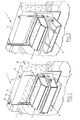
- a first preferred embodiment of a device 1 according to the present invention relates to a so-called float valve 1, comprising a substantially block-like elongate housing 2 provided with an opening 22 in the underside and an opening 26 in the rear side which communicate which each other for the passage of liquid.
- the rear side of the housing is coupled to a plate-like member 4 with corresponding opening 26 for fixing the housing therewith to a water-retaining structure 6 between two areas of differing level in which a corresponding opening 28 is likewise arranged for passage of liquid.
- hinged valve means comprising in the shown embodiment a substantially beam-shaped hollow floating body 8 for closing therewith the opening or openings in the underside of housing 2 when a desired difference in liquid level has been reached or this liquid level falls below the desired difference, and for leaving this opening or openings clear when the predetermined difference in liquid level is exceeded, both in the case the upper surface 10 rises above a determined level and the lower surface 12 falls below a determined level.
- Float valve 1 is fixed to the water-retaining structure 6 under liquid level 12, wherein pipes 14 and 16 protrude at one end above the liquid and are connected at the other end to floating body 8.
- a suitable liquid can be carried into floating body 8 by allowing a liquid to flow in via coupling piece 15, for instance using an external pump, or for removing liquid therefrom wherein tube 16 with curved upper part 18 provides the required venting and bleeding.
- the buoyancy of floating body 8 can thus be adapted to maintain a desired difference 20 which can be established for a shorter or longer period on either side thereof with relatively simple means (fig. 1, 2, 3 and 4).
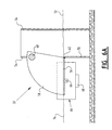
- a second embodiment according to the present invention (fig. 5) relates to a so-called floodgate valve 50 which is arranged in opening 52 in a water-retaining structure.
- Floodgate valve 50 comprises plates 54 which are arranged symmetrically in relation to each other in the water-retaining structure and which are L-shaped in top view for pivotal connection thereto of a plate 56, on both sides of which are arranged plates 58 of quarter-circle shape between which a ballast 60 is arranged at an angle of about 90° to pivot axis 62 relative to plate 56.
- a ballast 60 Arranged on both sides of plate 56 are floating bodies 64 which are rotatably connected to plate 56 at a predetermined location 66.
- a ballast 68 is arranged on the bottom of floating bodies 64 in order to damp undesirable movements, such as movement to and fro of the float members (fig. 5, 6a).
- the lowest reference level at which the floodgate valve 50 functions is determined by the height of pivot point 62, wherein the opening 52 in the water-retaining structure under pivot point 62 is closed by wall 70.
- the level 72 on one side of floodgate valve 50 is the same as level 74 on the other side (fig. 6a).
- the floating bodies 64 will also rise due to their buoyancy, so that plate 56 moves into an inclining position relative to water-retaining structure 54, wherein the outer end 76 of plate 56 protrudes above the level 74. Plate 56 acts here as an overflow, wherein as higher level the level 72 reaches the position of outer end 76 (fig. 6b).
- the extreme value of this rise is related to the position at which level 74 has risen such that plate 56 comes to lie in a vertical or almost vertical position (fig. 6c), wherein level 72 also reaches the maximum range of adjustment.
- the floodgate valve ensures that level 72 rises in a determined ratio relative to level 74, determined by the location of connection 66 to plate 56.
- Location 66 can be chosen such that the ratio in which the liquid levels 72 and 74 rise in relation to each other is roughly constant, assuming a starting position wherein the both levels are the same as shown in fig. 6a. This is of particular importance when areas of differing level are compartmentalized in the Westland (NL), wherein a desired reference level can be set per area of differing level.
- float members 64 are in a higher position relative to water level 74 since ballasts on the floating bodies have been omitted.
- Floating bodies 64 are connected via rods 76, 78 and 80 at location 66 to plate 56 and are also pivotally connected to water-retaining structure 70 at point 82.
- the operation of the third embodiment corresponds for a greater part to the operation of the second embodiment, wherein however, due to the predetermined ratio of the length of rods 76, 78, 80, the ratio of the rise in level 72 relative to level 74 can be substantially constant, linear or logarithmic. Ballast 60 provides the desired damping. There is a greater freedom of adjustment here due to the variation in the length of rods 76, 78, 80 and the location and size of the ballast, whereby the different constant, linear or logarithmic ratios are among the possibilities.
Landscapes
- Engineering & Computer Science (AREA)
- Structural Engineering (AREA)
- General Engineering & Computer Science (AREA)
- Mechanical Engineering (AREA)
- Civil Engineering (AREA)
- Float Valves (AREA)
- Level Indicators Using A Float (AREA)
- Closing And Opening Devices For Wings, And Checks For Wings (AREA)
- Power-Operated Mechanisms For Wings (AREA)
- Sanitary Device For Flush Toilet (AREA)
- Barrages (AREA)
- Flow Control (AREA)
Priority Applications (2)
| Application Number | Priority Date | Filing Date | Title |
|---|---|---|---|
| DK09000286.6T DK2042658T3 (en) | 2002-10-17 | 2003-10-15 | Float valve, swim-flood sport and method of use thereof |
| EP09000286.6A EP2042658B1 (fr) | 2002-10-17 | 2003-10-15 | Clapet à flotteur, déversoir à flotteur et méthode d'utilisation correspondante |
Applications Claiming Priority (2)
| Application Number | Priority Date | Filing Date | Title |
|---|---|---|---|
| NL1021680 | 2002-10-17 | ||
| NL1021680A NL1021680C2 (nl) | 2002-10-17 | 2002-10-17 | Vlotterklep, vlotterstuw en werkwijze voor het gebruik daarvan. |
Related Child Applications (1)
| Application Number | Title | Priority Date | Filing Date |
|---|---|---|---|
| EP09000286.6A Division EP2042658B1 (fr) | 2002-10-17 | 2003-10-15 | Clapet à flotteur, déversoir à flotteur et méthode d'utilisation correspondante |
Publications (3)
| Publication Number | Publication Date |
|---|---|
| EP1411172A2 true EP1411172A2 (fr) | 2004-04-21 |
| EP1411172A3 EP1411172A3 (fr) | 2004-08-11 |
| EP1411172B1 EP1411172B1 (fr) | 2009-04-15 |
Family
ID=32041051
Family Applications (2)
| Application Number | Title | Priority Date | Filing Date |
|---|---|---|---|
| EP03078257A Expired - Lifetime EP1411172B1 (fr) | 2002-10-17 | 2003-10-15 | Clapet à flotteur, porte contre les inondations à flotteur et son procédé d'utilisation |
| EP09000286.6A Expired - Lifetime EP2042658B1 (fr) | 2002-10-17 | 2003-10-15 | Clapet à flotteur, déversoir à flotteur et méthode d'utilisation correspondante |
Family Applications After (1)
| Application Number | Title | Priority Date | Filing Date |
|---|---|---|---|
| EP09000286.6A Expired - Lifetime EP2042658B1 (fr) | 2002-10-17 | 2003-10-15 | Clapet à flotteur, déversoir à flotteur et méthode d'utilisation correspondante |
Country Status (5)
| Country | Link |
|---|---|
| EP (2) | EP1411172B1 (fr) |
| AT (1) | ATE428827T1 (fr) |
| DE (1) | DE60327146D1 (fr) |
| DK (2) | DK1411172T3 (fr) |
| NL (1) | NL1021680C2 (fr) |
Cited By (2)
| Publication number | Priority date | Publication date | Assignee | Title |
|---|---|---|---|---|
| EP2915923A1 (fr) * | 2014-03-06 | 2015-09-09 | Antonios Toumazis | Barrière à commande automatique contre inondation, déversement et autres protections |
| EP3309301A4 (fr) * | 2015-06-05 | 2019-04-17 | Nippon KOEI Co., Ltd. | Dispositif d'ouverture et de fermeture |
Families Citing this family (1)
| Publication number | Priority date | Publication date | Assignee | Title |
|---|---|---|---|---|
| JP6227477B2 (ja) * | 2014-05-16 | 2017-11-08 | 日立造船株式会社 | 管路止水装置 |
Citations (5)
| Publication number | Priority date | Publication date | Assignee | Title |
|---|---|---|---|---|
| US1716698A (en) | 1927-02-14 | 1929-06-11 | Jermar Frantisek | Hydrostatic weir shutter |
| FR1237261A (fr) | 1959-06-17 | 1960-07-29 | Entpr D Equipements Mecaniques | Perfectionnements apportés aux vannes à secteur renversé |
| GB2294079A (en) | 1994-10-15 | 1996-04-17 | Cyril Anthony Timms | Adjustable counterbalanced self-regulatory tilting weir. |
| WO2001088292A1 (fr) | 2000-05-17 | 2001-11-22 | GÜTHLER, Renate | Procede et dispositif pour reguler des ecoulements et/ou epurer des canalisations |
| AU2986001A (en) | 2000-03-23 | 2002-07-25 | Auto Flow Gate Pty Ltd | Liquid level regulation apparatus |
Family Cites Families (1)
| Publication number | Priority date | Publication date | Assignee | Title |
|---|---|---|---|---|
| FR1273261A (fr) | 1959-11-17 | 1961-10-06 | Metal Box Co Ltd | Perfectionnements aux emballages |
-
2002
- 2002-10-17 NL NL1021680A patent/NL1021680C2/nl not_active IP Right Cessation
-
2003
- 2003-10-15 DE DE60327146T patent/DE60327146D1/de not_active Expired - Lifetime
- 2003-10-15 AT AT03078257T patent/ATE428827T1/de not_active IP Right Cessation
- 2003-10-15 EP EP03078257A patent/EP1411172B1/fr not_active Expired - Lifetime
- 2003-10-15 DK DK03078257T patent/DK1411172T3/da active
- 2003-10-15 DK DK09000286.6T patent/DK2042658T3/en active
- 2003-10-15 EP EP09000286.6A patent/EP2042658B1/fr not_active Expired - Lifetime
Patent Citations (5)
| Publication number | Priority date | Publication date | Assignee | Title |
|---|---|---|---|---|
| US1716698A (en) | 1927-02-14 | 1929-06-11 | Jermar Frantisek | Hydrostatic weir shutter |
| FR1237261A (fr) | 1959-06-17 | 1960-07-29 | Entpr D Equipements Mecaniques | Perfectionnements apportés aux vannes à secteur renversé |
| GB2294079A (en) | 1994-10-15 | 1996-04-17 | Cyril Anthony Timms | Adjustable counterbalanced self-regulatory tilting weir. |
| AU2986001A (en) | 2000-03-23 | 2002-07-25 | Auto Flow Gate Pty Ltd | Liquid level regulation apparatus |
| WO2001088292A1 (fr) | 2000-05-17 | 2001-11-22 | GÜTHLER, Renate | Procede et dispositif pour reguler des ecoulements et/ou epurer des canalisations |
Cited By (4)
| Publication number | Priority date | Publication date | Assignee | Title |
|---|---|---|---|---|
| EP2915923A1 (fr) * | 2014-03-06 | 2015-09-09 | Antonios Toumazis | Barrière à commande automatique contre inondation, déversement et autres protections |
| EP3309301A4 (fr) * | 2015-06-05 | 2019-04-17 | Nippon KOEI Co., Ltd. | Dispositif d'ouverture et de fermeture |
| US10415201B2 (en) | 2015-06-05 | 2019-09-17 | Nippon Koei Co., Ltd. | Opening/closing device |
| AU2015397438B2 (en) * | 2015-06-05 | 2020-09-10 | Kansei Company | Opening and closing device |
Also Published As
| Publication number | Publication date |
|---|---|
| EP1411172B1 (fr) | 2009-04-15 |
| ATE428827T1 (de) | 2009-05-15 |
| DE60327146D1 (de) | 2009-05-28 |
| NL1021680C2 (nl) | 2004-05-11 |
| DK2042658T3 (en) | 2016-12-05 |
| EP2042658B1 (fr) | 2016-08-10 |
| DK1411172T3 (da) | 2009-07-27 |
| EP2042658A1 (fr) | 2009-04-01 |
| EP1411172A3 (fr) | 2004-08-11 |
Similar Documents
| Publication | Publication Date | Title |
|---|---|---|
| US6510866B2 (en) | Ball cock assembly, float assembly for same, and method of controlling liquid level in a tank | |
| US5090443A (en) | Fluid level control float valve | |
| US6886589B2 (en) | Float valve | |
| US5655232A (en) | Fluid level control device and method | |
| CA2421801A1 (fr) | Ensemble de soupape automatique pour reservoir de rafraichisseur d'eau potable | |
| US8091581B2 (en) | Fluid level control toggle valve device and method | |
| KR102421205B1 (ko) | 자동 수위 조절 물꼬 | |
| EP1411172A2 (fr) | Clapet à flotteur, porte contre les inondations à flotteur et son procédé d'utilisation | |
| KR101790145B1 (ko) | 어도가 구비된 수문 | |
| KR101922524B1 (ko) | 저수조용 수문 | |
| KR102192508B1 (ko) | 자동 수위조절 물꼬 | |
| EP2805090B1 (fr) | Ensemble clapet | |
| KR101989601B1 (ko) | 담수기능을 갖는 도로경계블록 | |
| RU2609952C1 (ru) | Вакуумная дренажная система | |
| US7740032B2 (en) | System and method for automatically filling a liquid receptacle | |
| KR20150142561A (ko) | 논물 수위 조절장치 | |
| RU2546854C1 (ru) | Устройство для регулирования уровня воды в закрытой дренажной сети | |
| KR101313372B1 (ko) | 비상다리가 구성되어 있는 가동보 | |
| JP5116460B2 (ja) | 水路用の水位調整ゲート | |
| AU2004200168B2 (en) | A liquid level control device | |
| US20060096659A1 (en) | System and method for automatically filling a liquid receptacle | |
| CN207714252U (zh) | 一种用于市政工程中水利设施的自动泥沙导除结构 | |
| JP4724790B2 (ja) | 水路等に設ける逆流防止装置 | |
| FI13340Y1 (fi) | Kaivon purkuveden virtauksensäätöjärjestelmä | |
| KR102868352B1 (ko) | 수위조절을 위한 자동 개폐 물꼬 |
Legal Events
| Date | Code | Title | Description |
|---|---|---|---|
| PUAI | Public reference made under article 153(3) epc to a published international application that has entered the european phase |
Free format text: ORIGINAL CODE: 0009012 |
|
| AK | Designated contracting states |
Kind code of ref document: A2 Designated state(s): AT BE BG CH CY CZ DE DK EE ES FI FR GB GR HU IE IT LI LU MC NL PT RO SE SI SK TR |
|
| AX | Request for extension of the european patent |
Extension state: AL LT LV MK |
|
| PUAL | Search report despatched |
Free format text: ORIGINAL CODE: 0009013 |
|
| RIC1 | Information provided on ipc code assigned before grant |
Ipc: 7E 02B 7/44 B Ipc: 7E 02B 7/20 A |
|
| AK | Designated contracting states |
Kind code of ref document: A3 Designated state(s): AT BE BG CH CY CZ DE DK EE ES FI FR GB GR HU IE IT LI LU MC NL PT RO SE SI SK TR |
|
| AX | Request for extension of the european patent |
Extension state: AL LT LV MK |
|
| 17P | Request for examination filed |
Effective date: 20041210 |
|
| AKX | Designation fees paid |
Designated state(s): AT BE BG CH CY CZ DE DK EE ES FI FR GB GR HU IE IT LI LU MC NL PT RO SE SI SK TR |
|
| 17Q | First examination report despatched |
Effective date: 20060208 |
|
| GRAP | Despatch of communication of intention to grant a patent |
Free format text: ORIGINAL CODE: EPIDOSNIGR1 |
|
| GRAS | Grant fee paid |
Free format text: ORIGINAL CODE: EPIDOSNIGR3 |
|
| GRAA | (expected) grant |
Free format text: ORIGINAL CODE: 0009210 |
|
| AK | Designated contracting states |
Kind code of ref document: B1 Designated state(s): AT BE BG CH CY CZ DE DK EE ES FI FR GB GR HU IE IT LI LU MC NL PT RO SE SI SK TR |
|
| REG | Reference to a national code |
Ref country code: CH Ref legal event code: EP Ref country code: GB Ref legal event code: FG4D |
|
| REG | Reference to a national code |
Ref country code: IE Ref legal event code: FG4D |
|
| REF | Corresponds to: |
Ref document number: 60327146 Country of ref document: DE Date of ref document: 20090528 Kind code of ref document: P |
|
| REG | Reference to a national code |
Ref country code: DK Ref legal event code: T3 |
|
| PG25 | Lapsed in a contracting state [announced via postgrant information from national office to epo] |
Ref country code: AT Free format text: LAPSE BECAUSE OF FAILURE TO SUBMIT A TRANSLATION OF THE DESCRIPTION OR TO PAY THE FEE WITHIN THE PRESCRIBED TIME-LIMIT Effective date: 20090415 Ref country code: ES Free format text: LAPSE BECAUSE OF FAILURE TO SUBMIT A TRANSLATION OF THE DESCRIPTION OR TO PAY THE FEE WITHIN THE PRESCRIBED TIME-LIMIT Effective date: 20090726 Ref country code: PT Free format text: LAPSE BECAUSE OF FAILURE TO SUBMIT A TRANSLATION OF THE DESCRIPTION OR TO PAY THE FEE WITHIN THE PRESCRIBED TIME-LIMIT Effective date: 20090915 Ref country code: FI Free format text: LAPSE BECAUSE OF FAILURE TO SUBMIT A TRANSLATION OF THE DESCRIPTION OR TO PAY THE FEE WITHIN THE PRESCRIBED TIME-LIMIT Effective date: 20090415 |
|
| PG25 | Lapsed in a contracting state [announced via postgrant information from national office to epo] |
Ref country code: SI Free format text: LAPSE BECAUSE OF FAILURE TO SUBMIT A TRANSLATION OF THE DESCRIPTION OR TO PAY THE FEE WITHIN THE PRESCRIBED TIME-LIMIT Effective date: 20090415 Ref country code: SE Free format text: LAPSE BECAUSE OF FAILURE TO SUBMIT A TRANSLATION OF THE DESCRIPTION OR TO PAY THE FEE WITHIN THE PRESCRIBED TIME-LIMIT Effective date: 20090715 |
|
| PG25 | Lapsed in a contracting state [announced via postgrant information from national office to epo] |
Ref country code: RO Free format text: LAPSE BECAUSE OF FAILURE TO SUBMIT A TRANSLATION OF THE DESCRIPTION OR TO PAY THE FEE WITHIN THE PRESCRIBED TIME-LIMIT Effective date: 20090415 Ref country code: CZ Free format text: LAPSE BECAUSE OF FAILURE TO SUBMIT A TRANSLATION OF THE DESCRIPTION OR TO PAY THE FEE WITHIN THE PRESCRIBED TIME-LIMIT Effective date: 20090415 Ref country code: EE Free format text: LAPSE BECAUSE OF FAILURE TO SUBMIT A TRANSLATION OF THE DESCRIPTION OR TO PAY THE FEE WITHIN THE PRESCRIBED TIME-LIMIT Effective date: 20090415 |
|
| PLBE | No opposition filed within time limit |
Free format text: ORIGINAL CODE: 0009261 |
|
| STAA | Information on the status of an ep patent application or granted ep patent |
Free format text: STATUS: NO OPPOSITION FILED WITHIN TIME LIMIT |
|
| PG25 | Lapsed in a contracting state [announced via postgrant information from national office to epo] |
Ref country code: SK Free format text: LAPSE BECAUSE OF FAILURE TO SUBMIT A TRANSLATION OF THE DESCRIPTION OR TO PAY THE FEE WITHIN THE PRESCRIBED TIME-LIMIT Effective date: 20090415 |
|
| 26N | No opposition filed |
Effective date: 20100118 |
|
| PG25 | Lapsed in a contracting state [announced via postgrant information from national office to epo] |
Ref country code: BG Free format text: LAPSE BECAUSE OF FAILURE TO SUBMIT A TRANSLATION OF THE DESCRIPTION OR TO PAY THE FEE WITHIN THE PRESCRIBED TIME-LIMIT Effective date: 20090715 |
|
| PG25 | Lapsed in a contracting state [announced via postgrant information from national office to epo] |
Ref country code: MC Free format text: LAPSE BECAUSE OF NON-PAYMENT OF DUE FEES Effective date: 20091031 |
|
| REG | Reference to a national code |
Ref country code: CH Ref legal event code: PL |
|
| PG25 | Lapsed in a contracting state [announced via postgrant information from national office to epo] |
Ref country code: LI Free format text: LAPSE BECAUSE OF NON-PAYMENT OF DUE FEES Effective date: 20091031 Ref country code: CH Free format text: LAPSE BECAUSE OF NON-PAYMENT OF DUE FEES Effective date: 20091031 Ref country code: GR Free format text: LAPSE BECAUSE OF FAILURE TO SUBMIT A TRANSLATION OF THE DESCRIPTION OR TO PAY THE FEE WITHIN THE PRESCRIBED TIME-LIMIT Effective date: 20090716 |
|
| PG25 | Lapsed in a contracting state [announced via postgrant information from national office to epo] |
Ref country code: IT Free format text: LAPSE BECAUSE OF FAILURE TO SUBMIT A TRANSLATION OF THE DESCRIPTION OR TO PAY THE FEE WITHIN THE PRESCRIBED TIME-LIMIT Effective date: 20090415 |
|
| PG25 | Lapsed in a contracting state [announced via postgrant information from national office to epo] |
Ref country code: LU Free format text: LAPSE BECAUSE OF NON-PAYMENT OF DUE FEES Effective date: 20091015 |
|
| PG25 | Lapsed in a contracting state [announced via postgrant information from national office to epo] |
Ref country code: HU Free format text: LAPSE BECAUSE OF FAILURE TO SUBMIT A TRANSLATION OF THE DESCRIPTION OR TO PAY THE FEE WITHIN THE PRESCRIBED TIME-LIMIT Effective date: 20091016 |
|
| PG25 | Lapsed in a contracting state [announced via postgrant information from national office to epo] |
Ref country code: TR Free format text: LAPSE BECAUSE OF FAILURE TO SUBMIT A TRANSLATION OF THE DESCRIPTION OR TO PAY THE FEE WITHIN THE PRESCRIBED TIME-LIMIT Effective date: 20090415 |
|
| PG25 | Lapsed in a contracting state [announced via postgrant information from national office to epo] |
Ref country code: CY Free format text: LAPSE BECAUSE OF FAILURE TO SUBMIT A TRANSLATION OF THE DESCRIPTION OR TO PAY THE FEE WITHIN THE PRESCRIBED TIME-LIMIT Effective date: 20090415 |
|
| REG | Reference to a national code |
Ref country code: FR Ref legal event code: PLFP Year of fee payment: 13 |
|
| REG | Reference to a national code |
Ref country code: FR Ref legal event code: PLFP Year of fee payment: 14 |
|
| REG | Reference to a national code |
Ref country code: NL Ref legal event code: RC Free format text: DETAILS LICENCE OR PLEDGE: RIGHT OF PLEDGE, ESTABLISHED Name of requester: COOEPERATIEVE RABOBANK U.A. Effective date: 20170224 |
|
| REG | Reference to a national code |
Ref country code: FR Ref legal event code: PLFP Year of fee payment: 15 |
|
| REG | Reference to a national code |
Ref country code: FR Ref legal event code: PLFP Year of fee payment: 16 |
|
| PGFP | Annual fee paid to national office [announced via postgrant information from national office to epo] |
Ref country code: NL Payment date: 20181026 Year of fee payment: 16 |
|
| PGFP | Annual fee paid to national office [announced via postgrant information from national office to epo] |
Ref country code: DE Payment date: 20181029 Year of fee payment: 16 Ref country code: DK Payment date: 20181029 Year of fee payment: 16 Ref country code: IE Payment date: 20181025 Year of fee payment: 16 |
|
| PGFP | Annual fee paid to national office [announced via postgrant information from national office to epo] |
Ref country code: GB Payment date: 20181029 Year of fee payment: 16 Ref country code: FR Payment date: 20181025 Year of fee payment: 16 Ref country code: BE Payment date: 20181029 Year of fee payment: 16 |
|
| REG | Reference to a national code |
Ref country code: DE Ref legal event code: R119 Ref document number: 60327146 Country of ref document: DE |
|
| REG | Reference to a national code |
Ref country code: DK Ref legal event code: EBP Effective date: 20191031 |
|
| REG | Reference to a national code |
Ref country code: NL Ref legal event code: MM Effective date: 20191101 |
|
| PG25 | Lapsed in a contracting state [announced via postgrant information from national office to epo] |
Ref country code: DE Free format text: LAPSE BECAUSE OF NON-PAYMENT OF DUE FEES Effective date: 20200501 |
|
| REG | Reference to a national code |
Ref country code: BE Ref legal event code: MM Effective date: 20191031 Ref country code: BE Ref legal event code: RC Free format text: DETAILS PLEDGE: RIGHT OF PLEDGE, ETABLI Name of requester: COOEPERATIEVE RABOBANK U.A. Effective date: 20170601 |
|
| PG25 | Lapsed in a contracting state [announced via postgrant information from national office to epo] |
Ref country code: BE Free format text: LAPSE BECAUSE OF NON-PAYMENT OF DUE FEES Effective date: 20191031 Ref country code: NL Free format text: LAPSE BECAUSE OF NON-PAYMENT OF DUE FEES Effective date: 20191101 |
|
| GBPC | Gb: european patent ceased through non-payment of renewal fee |
Effective date: 20191015 |
|
| PG25 | Lapsed in a contracting state [announced via postgrant information from national office to epo] |
Ref country code: FR Free format text: LAPSE BECAUSE OF NON-PAYMENT OF DUE FEES Effective date: 20191031 Ref country code: IE Free format text: LAPSE BECAUSE OF NON-PAYMENT OF DUE FEES Effective date: 20191015 Ref country code: DK Free format text: LAPSE BECAUSE OF NON-PAYMENT OF DUE FEES Effective date: 20191031 Ref country code: GB Free format text: LAPSE BECAUSE OF NON-PAYMENT OF DUE FEES Effective date: 20191015 |