EP1411192A1 - Umstellbares Zylinderschlo mit seitlichem Riegel - Google Patents
Umstellbares Zylinderschlo mit seitlichem Riegel Download PDFInfo
- Publication number
- EP1411192A1 EP1411192A1 EP20030256428 EP03256428A EP1411192A1 EP 1411192 A1 EP1411192 A1 EP 1411192A1 EP 20030256428 EP20030256428 EP 20030256428 EP 03256428 A EP03256428 A EP 03256428A EP 1411192 A1 EP1411192 A1 EP 1411192A1
- Authority
- EP
- European Patent Office
- Prior art keywords
- side bar
- tumbler
- plug
- casing
- variable
- Prior art date
- Legal status (The legal status is an assumption and is not a legal conclusion. Google has not performed a legal analysis and makes no representation as to the accuracy of the status listed.)
- Granted
Links
Images


Classifications
-
- E—FIXED CONSTRUCTIONS
- E05—LOCKS; KEYS; WINDOW OR DOOR FITTINGS; SAFES
- E05B—LOCKS; ACCESSORIES THEREFOR; HANDCUFFS
- E05B29/00—Cylinder locks and other locks with plate tumblers which are set by pushing the key in
-
- E—FIXED CONSTRUCTIONS
- E05—LOCKS; KEYS; WINDOW OR DOOR FITTINGS; SAFES
- E05B—LOCKS; ACCESSORIES THEREFOR; HANDCUFFS
- E05B29/00—Cylinder locks and other locks with plate tumblers which are set by pushing the key in
- E05B29/004—Cylinder locks and other locks with plate tumblers which are set by pushing the key in with changeable combinations
-
- E—FIXED CONSTRUCTIONS
- E05—LOCKS; KEYS; WINDOW OR DOOR FITTINGS; SAFES
- E05B—LOCKS; ACCESSORIES THEREFOR; HANDCUFFS
- E05B29/00—Cylinder locks and other locks with plate tumblers which are set by pushing the key in
- E05B29/0066—Side bar locking
-
- Y—GENERAL TAGGING OF NEW TECHNOLOGICAL DEVELOPMENTS; GENERAL TAGGING OF CROSS-SECTIONAL TECHNOLOGIES SPANNING OVER SEVERAL SECTIONS OF THE IPC; TECHNICAL SUBJECTS COVERED BY FORMER USPC CROSS-REFERENCE ART COLLECTIONS [XRACs] AND DIGESTS
- Y10—TECHNICAL SUBJECTS COVERED BY FORMER USPC
- Y10T—TECHNICAL SUBJECTS COVERED BY FORMER US CLASSIFICATION
- Y10T70/00—Locks
- Y10T70/70—Operating mechanism
- Y10T70/7441—Key
- Y10T70/7486—Single key
- Y10T70/7508—Tumbler type
- Y10T70/7559—Cylinder type
- Y10T70/7588—Rotary plug
- Y10T70/7593—Sliding tumblers
- Y10T70/7599—Transverse of plug
-
- Y—GENERAL TAGGING OF NEW TECHNOLOGICAL DEVELOPMENTS; GENERAL TAGGING OF CROSS-SECTIONAL TECHNOLOGIES SPANNING OVER SEVERAL SECTIONS OF THE IPC; TECHNICAL SUBJECTS COVERED BY FORMER USPC CROSS-REFERENCE ART COLLECTIONS [XRACs] AND DIGESTS
- Y10—TECHNICAL SUBJECTS COVERED BY FORMER USPC
- Y10T—TECHNICAL SUBJECTS COVERED BY FORMER US CLASSIFICATION
- Y10T70/00—Locks
- Y10T70/70—Operating mechanism
- Y10T70/7441—Key
- Y10T70/7486—Single key
- Y10T70/7508—Tumbler type
- Y10T70/7559—Cylinder type
- Y10T70/7588—Rotary plug
- Y10T70/7593—Sliding tumblers
- Y10T70/7599—Transverse of plug
- Y10T70/7616—Including sidebar
-
- Y—GENERAL TAGGING OF NEW TECHNOLOGICAL DEVELOPMENTS; GENERAL TAGGING OF CROSS-SECTIONAL TECHNOLOGIES SPANNING OVER SEVERAL SECTIONS OF THE IPC; TECHNICAL SUBJECTS COVERED BY FORMER USPC CROSS-REFERENCE ART COLLECTIONS [XRACs] AND DIGESTS
- Y10—TECHNICAL SUBJECTS COVERED BY FORMER USPC
- Y10T—TECHNICAL SUBJECTS COVERED BY FORMER US CLASSIFICATION
- Y10T70/00—Locks
- Y10T70/70—Operating mechanism
- Y10T70/7441—Key
- Y10T70/7729—Permutation
- Y10T70/7734—Automatically key set combinations
-
- Y—GENERAL TAGGING OF NEW TECHNOLOGICAL DEVELOPMENTS; GENERAL TAGGING OF CROSS-SECTIONAL TECHNOLOGIES SPANNING OVER SEVERAL SECTIONS OF THE IPC; TECHNICAL SUBJECTS COVERED BY FORMER USPC CROSS-REFERENCE ART COLLECTIONS [XRACs] AND DIGESTS
- Y10—TECHNICAL SUBJECTS COVERED BY FORMER USPC
- Y10T—TECHNICAL SUBJECTS COVERED BY FORMER US CLASSIFICATION
- Y10T70/00—Locks
- Y10T70/70—Operating mechanism
- Y10T70/7441—Key
- Y10T70/7729—Permutation
- Y10T70/774—Adjustable tumblers
Definitions
- the present invention relates to a side bar type cylinder lock with a variable key code.
- This conventional cylinder lock comprises:
- the conventional cylinder lock with the variable key code having the above construction: since the reset-key insertion hole for driving the retractor is formed in a front surface of the plug in addition to the ordinary keyhole, the conventional cylinder lock with the variable key code is quite different in appearance from the ordinary cylinder lock of a single-keyhole type due to the presence of the reset-key insertion hole. As a result, the conventional cylinder lock with the variable key code tends to enhance tampering of the reset-key insertion hole by an unauthorized person. For example, such an unauthorized person often fills up the reset-key insertion hole with foreign matter, which often makes it impossible for an authorized person or user to change the key code of the conventional cylinder lock.
- the conventional cylinder lock with the variable key code requires many complicated components and therefore a complicated mechanism for changing the key code, it is not possible to produce the conventional cylinder lock with the variable key code at low cost.
- the cylinder lock of the present invention is provided with a plug.
- the plug is provided with only one keyhole in its front surface. Due to this, the cylinder lock of the present invention is excellent in appearance and may discourage tempering of its keyhole. Further, the cylinder lock of the present invention is excellent in easiness in use when its key code is changed. Still further, the cylinder lock of the present invention is simple in construction since it does not require a reset key nor a retractor, wherein both the reset key and the retractor are essential components of the conventional cylinder lock capable of changing its key code. Due to this simple construction, it is possible to produce the cylinder lock of the present invention at low cost.
- the above object of the present invention is accomplished by providing:
- the sleeve-like casing is provided with both a variable-tumbler engaging concave portion in its inner peripheral surface;
- the variable tumbler has one of its end portions formed into a locking projection; and, when the front end portion of the side bar is engaged with the side bar engaging concave portion of the sleeve-like casing and the proximal end portion of the side bar abuts against the side end portion of the tumbler plate, the locking projection of the variable tumbler is engaged with the variable-tumbler engaging concave portion of the sleeve-like casing.
- a side bar type cylinder lock of the present invention is provided with a variable key code.
- the cylinder lock of the present invention is provided with a sleeve-like casing 1.
- This casing 1 is provided with both a side bar holder engaging concave portion 2 and a side bar engaging concave portion 5 in an inner peripheral surface of the casing 1
- a plug 6 is rotatably, but not axially slidably, mounted in the sleeve-like casing 1.
- the plug 6 is provided with: a keyhole 7 which opens into a front surface of the plug 6 to axially extend in the plug 6; a plurality of tumbler insertion holes 8 each intersecting the keyhole 7 of the plug 6; a side bar holder receiving hole 9 formed in one of opposite sides of each of the tumbler insertion holes 8; and a spring receiving hole 10 formed in the other of the opposite sides of each of the tumbler insertion holes 8.
- the cylinder lock of the present invention is provided with a plurality of tumbler plates 11 each slidably mounted in the tumbler insertion hole 8 of the plug 6, wherein: each,of the tumbler plates 11 has one of its opposite side surfaces formed into a side end portion 26 provided with a side bar engaging concave portion 12, while each tumbler plate 11 has the other of the opposite side surfaces formed into an engaging portion 13.
- the cylinder lock of the present invention is provided with a plurality of variable tumblers 14 each slidably mounted in the tumbler insertion hole 8 of the plug 6, wherein: the variable tumbler 14 has one of its opposite side surfaces formed into a saw-toothed engaged portion 15 capable of detachably engaging with the engaging portion 13 of the tumbler plate 11; and the variable tumbler 14 has its central portion provided with a key passing hole 17 communicating with the keyhole 7.
- a spring 18 is received in the spring receiving hole 10 of the plug 6 to resiliently bias the variable tumbler 14 toward the inner peripheral surface of the sleeve-like casing 1.
- a side bar holder 19 is slidably mounted in the side bar holder receiving hole 9 of the plug 6.
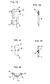
- the side bar holder 19 has one of its opposite surfaces bulged outwardly and formed the thus bulged surface into a bulged portion 21 and has its central portion provided with a side bar receiving hole 20 shown in Fig. 13.
- the bulged portion 21 of the side bar holder 19 enters the side bar holder engaging concave hole 2 of the sleeve-like casing 1 to engage with the side bar holder engaging concave hole 2.
- a side bar 22 (shown in Fig. 14) is slidably mounted in the side bar receiving hole 20 of the side bar holder 19. More specifically, the side bar 22 has its front end portion 23 biased in a biasing direction toward the side bar engaging concave portion 5 of the sleeve-like casing 1 so as to engage therewith.
- the side bar 22 is moved in a direction opposite to the above-mentioned biasing direction of the side bar 22 to have its proximal end portion 24 engaged with the side bar engaging concave portion 12 of the tumbler plate 11.
- the cylinder lock of the present invention is provided with a spring 25 (shown in Fig. 19) for biasing the tumbler plate 11 toward the side bar holder 19.
- the spring 25 resiliently forces the side end portion 26 of the tumbler plate 11 to enter the side bar holder receiving hole 9 of the plug 6, and resiliently forces the bulged portion 21 of the side bar holder 19 to enter the side bar holder engaging concave portion 2 of the sleeve-like casing 1, and further resiliently forces the engaging portion 13 of the tumbler plate 11 to disengage from the engaged portion 15 of the variable tumbler 14.
- the sleeve-like casing 1 is provided with both a variable-tumbler engaging concave portion 3, 4 in its inner peripheral surface.
- the variable tumbler 14 has one of its end portions formed into a locking projection 16.
- the side bar 22 In the locked condition, the side bar 22 has its front end portion 23 engaged with the side bar engaging concave portion 5 of the sleeve-like casing 1, and has its proximal end portion 24 abut against the side end portion 26 of the tumbler plate 11, so that the side bar 22 is held in its locked position shown in Fig. 5.
- the tumbler plate 11 In the locked condition, the tumbler plate 11 is positioned in the closest vicinity to the variable tumbler 14 to have its engaging portion 13 meshed with the saw-toothed engaged portion 15 of the variable tumbler 14.
- the key K (shown in Fig. 3) corresponding to the current key code is inserted into the keyhole 7 of the cylinder lock.
- the key K is provided with a key code portion (i.e., "bit portion #1, #2") formed in an edge portion of the key K.
- bit portion #1, #2 the key code portion #1, #2" of the key pushes an inner end surface of the key passing hole 17 of each of the variable tumblers 14, so that each of the variable tumblers 14 and each of the tumbler plates 11 each meshed with the corresponding variable tumbler 14 are integrally, slidably and radially moved, whereby the locking projection 16 of each of the variable tumblers 14 is disengaged from the variable-tumbler engaging concave portion 3 of the sleeve-like casing 1.
- the side bar engaging concave portion 12 of the tumbler plate 11 is moved to a position in which the side bar engaging concave portion 12 is oppositely disposed from a rear end portion 24 of the side bar 22.
- the front end portion 23 of the side bar 22 forces its oblique cam surface slide to slide on the corresponding oblique cam surface of the side bar engaging concave portion 5 of the casing 1 so that the side bar 22 is disengaged from the casing 1, while the rear end portion 24 of the side bar 22 enters the side bar engaging concave portion 12 of the tumbler plate 11 and is engaged with the tumbler plate 11.
- the plug 6 is rotatably driven through a predetermined angle so as to move the side bar holder 19 to a position immediately before a key change position where the side bar holder 19 is oppositely disposed from the side bar holder engaging concave portion 2 of the casing 1. As a result, the plug 6 reaches an unlocking position thereof.
- the side bar engaging concave portion 12 of the tumbler plate 11 is moved to a position in which the side bar engaging concave portion 12 is oppositely disposed from a rear end portion 24 of the side bar 22.
- the front end portion 23 of the side bar 22 forces its oblique cam surface slide to slide on the corresponding oblique cam surface of the side bar engaging concave portion 5 of the casing 1 so that the side bar 22 is disengaged from the side bar engaging concave portion 5 of the casing 1, while the rear end portion 24 of the side bar 22 enters the side bar engaging concave portion 12 of the tumbler plate 11.
- the plug 6 is rotatably driven through a predetermined angle so that the side bar holder 19 reaches to a key change position in which the side bar holder 19 confronts with the side bar holder engaging concave portion 2 of the casing 1.
- the side end portion 26 of the tumbler plate 11 enters the side bar holder receiving hole 9 of the plug 6 under the influence of a resilient force exerted by the spring 25 to push the side bar holder 19 leftward, as viewed in Fig. 5.
- the side bar holder 19 thus pushed leftward has its bulged portion 21 enter the side bar holder engaging concave portion 2 of the casing 1. Due to this, the tumbler plate 11 is moved away from the variable tumbler 14 to have its engaging portion 13 completely disengaged from the saw-toothed engaged portion 15 of the variable tumbler 14.
- the change key CK is moved back and forth in a longitudinal direction of the tumbler insertion hole 8 of the plug 6 (i.e., in a direction perpendicular to a longitudinal direction of the plug 6), so that each of the variable tumblers 14 is forcibly moved.
- each of the tumbler plates 11 has its side end portion 26 engaged with the side bar holder receiving hole 9 of the plug 6 and is therefore kept in its fixed position, while each of the variable tumblers 14 is moved relative to each of the tumbler plates thus kept stationary in the fixed position thereof.
- the change key CK is removed from the keyhole 7 of the cylinder lock.
- a new key K having the new key code is inserted into the keyhole 7 and rotated clockwise as viewed in Fig. 7, so that a side surface of the bulged portion 21 of the side bar holder 19 is pushed back into the side bar holder receiving hole 9 of the plug 6, whereby the side surface end portion 26 of each of the tumbler plates 11 is pushed out of the side bar holder receiving hole 9 of the plug 6.
- each of the tumbler plates 11 to move to each of the corresponding variable tumblers 14, so that the engaging portion 13 of each tumbler plate 11 is engaged with the saw-toothed engaged portion 15 of each of the corresponding variable tumblers 14 in another engagement area of each saw-toothed engaged portion 15, which another engagement area is different from the previous engagement area of the saw-toothed engaged portion 15 of each variable tumbler 14 with respect to the engaging portion 13 of each tumbler plate 11.
- the variable tumbler 14 is provided with a spring support portion 27 in its side portion opposite to the saw-toothed engaged portion 15 thereof.
- the spring 18 for biasing the variable tumbler 14 is constructed of a compression coil spring. As is clear from Fig. 5, the spring 18 is compressed and mounted between the spring receiving hole 10 of the plug 6 and the spring support portion 27 of the variable tumbler 14.
- the tumbler plate 11 is provided with a pair of the engaging portions 13 in its opposite ends, between which a spring support member 28 constructed of a pin and the like is fixedly mounted on a rear surface of the tumbler plate to extend in a direction perpendicular to the plane of the tumbler plate 11.
- the spring support member 28 may be constructed of an embossed portion of the tumbler plate 11.
- the spring 25 for biasing the tumbler plate 11 is constructed of a torsion coil spring comprising: a central coil portion 25a; a pair of linear portions 25b, 25c each extending each of opposite ends of the central coil portion 25a; and, a pair of front end curled portions 25d, 25e, wherein the front end curled portions 25d and 25e extend from the linear portions 25b and 25c, respectively.
- the front end curled portions 25d, 25e of the spring 25 abut against the side surface of the variable tumbler 14.
- a distance between: a line passing through a center of each of the front end curled portions 25d, 25e of the spring 25; and a line passing through a center of the coil portion 25a of the spring varies when the tumbler plate 11 is moved to and away from the variable tumbler 14.
- both the spring 25 for biasing the tumbler plate 11 and the spring support member 28 are received in a recessed groove portion 29, which is formed in one of opposite radially extending inner wall surfaces of each of the tumbler insertion holes 8 of the plug 6.
- the keyhole 7 is radially offset with respect to a center of the plug 6.
- the bulged portion 21 of the side bar holder 19 has a low mountain-like profile.
- the side bar 22 has a hexagonal shape in cross section, and has each of the front end portion 23 and the rear end portion 24 thereof formed into a mountain-like shape.
- a guide projection 30 is formed in a rear surface of the spring support portion 27 of the variable tumbler 14. In operation, when the variable tumbler 14 slidably moves in a direction perpendicular to the longitudinal direction of the plug 6, the guide projection 30 moves in the spring receiving hole 10.
- a rotation angle control plate and a fastening plate are fixedly mounted on a rear end portion of the plug 6.
- the side bar type cylinder lock of the present invention provided with the variable code, when the user wants to change the current key code to a new one, it is necessary for the user to insert a new key K into the keyhole 7 and rotate the plug 6 in a manner such that the bulged portion 21 of the side bar holder 19 is oppositely disposed from the side bar holder engaging concave portion 2 of the casing 1.
- the side surface portion 26 of the tumbler plate 11 enters the side bar holder receiving hole 9 of the plug 6 under the influence of a resilient force exerted by the spring 25.
- variable tumbler 14 should be rotated through a predetermined angle. After that, the engaging portions 13 of the tumbler plate 11 are engaged again with the saw-toothed engaged portions 15 of the variable tumbler 14 so that the key code of the cylinder lock of the present invention is changed from the previous key code to a new key code.
- the cylinder lock of the present invention to change the key code in an easy manner as described above.
- the cylinder lock of the present invention which is also capable of changing its key code, does not require any reset key and any retractor both of which are essential components of the conventional cylinder lock. This enables the cylinder lock of the present invention to reduce the number of its components. Therefore, it is possible of the cylinder lock of the present invention to realize a considerable cost reduction and to simplified in mechanisms for changing the key code.
- the cylinder lock of the present invention is provided with only one aperture (i.e., keyhole 7) in the front surface of the plug 6. Due to this, the cylinder lock of the present invention is improved also in appearance and in resistance to attack.
- the tumbler plate 11 and the variable tumbler 14 are combined in a manner such that the engaging portion 13 of the tumbler plate 11 is engaged with the engaged portion 15 of the variable tumbler 14, wherein the tumbler plate 11 and the variable tumbler 14 thus combined with each other are inserted into the tumbler insertion hole 8 of the plug 6; the locking projection 16 of the variable tumbler 14 is engaged with the variable tumbler engaging concave portion 3 of the casing 1; the front end portion 23 of the side bar 22 having received in the side bar receiving hole 20 of the side bar holder 19 is engaged with the side bar engaging concave portion 5 of the casing 1; and the proximal end portion 24 of the side bar 22 is brought into abutting-contact with the side surface end portion 26 of the tumbler plate 11.
- the cylinder lock of the present invention Due to this, it is possible of the cylinder lock of the present invention to lock the plug 6 to the casing 1 in two portions, one of which is the locking projection 16 of the variable tumbler 14 and the other is the side bar 22. This prevents the plug 6 from rotating relative to the casing 1 in the lock state of the cylinder lock of the present invention, without fail. Consequently, it is possible to considerably improve the cylinder lock of the present invention in its locking ability.
Landscapes
- Physics & Mathematics (AREA)
- Electromagnetism (AREA)
- Lock And Its Accessories (AREA)
- Fluid-Damping Devices (AREA)
- Pens And Brushes (AREA)
- Supports Or Holders For Household Use (AREA)
Applications Claiming Priority (2)
| Application Number | Priority Date | Filing Date | Title |
|---|---|---|---|
| JP2002300965 | 2002-10-15 | ||
| JP2002300965A JP3776078B2 (ja) | 2002-10-15 | 2002-10-15 | サイドバー方式の可変コード型シリンダー錠 |
Publications (2)
| Publication Number | Publication Date |
|---|---|
| EP1411192A1 true EP1411192A1 (de) | 2004-04-21 |
| EP1411192B1 EP1411192B1 (de) | 2006-01-04 |
Family
ID=32040792
Family Applications (1)
| Application Number | Title | Priority Date | Filing Date |
|---|---|---|---|
| EP20030256428 Expired - Lifetime EP1411192B1 (de) | 2002-10-15 | 2003-10-11 | Umstellbares Zylinderschlo mit seitlichem Riegel |
Country Status (8)
| Country | Link |
|---|---|
| US (1) | US6755063B2 (de) |
| EP (1) | EP1411192B1 (de) |
| JP (1) | JP3776078B2 (de) |
| KR (1) | KR100489987B1 (de) |
| CN (1) | CN100395423C (de) |
| AT (1) | ATE315149T1 (de) |
| DE (1) | DE60303099T2 (de) |
| TW (1) | TWI221170B (de) |
Cited By (2)
| Publication number | Priority date | Publication date | Assignee | Title |
|---|---|---|---|---|
| WO2007028308A1 (fr) * | 2005-09-09 | 2007-03-15 | Malafon Electronic (Suzhou) Co., Ltd. | Serrure multi-fonctionnelle |
| EP1781876A4 (de) * | 2004-07-09 | 2014-05-28 | Kwikset Corp | Veränderbare schlossanordnung |
Families Citing this family (39)
| Publication number | Priority date | Publication date | Assignee | Title |
|---|---|---|---|---|
| AUPR838701A0 (en) * | 2001-10-19 | 2001-11-15 | Cylock Pty Ltd | Improved lock |
| US7634930B2 (en) | 2002-01-03 | 2009-12-22 | Strattec Security Corporation | Lock apparatus and method |
| US6860131B2 (en) * | 2002-09-26 | 2005-03-01 | Newfrey Llc | Rekeying a lock assembly |
| US6862909B2 (en) * | 2002-09-26 | 2005-03-08 | Newfrey Llc | Devices, methods, and systems for keying a lock assembly |
| US8347678B2 (en) * | 2002-09-26 | 2013-01-08 | Newfrey, Llc | Rekeyable lock cylinder assembly |
| US7114357B2 (en) | 2002-09-26 | 2006-10-03 | Newfrey, Llc | Keying system and method |
| CA2517887C (en) * | 2003-03-04 | 2011-09-13 | Newfrey Llc | Rekeyable lock cylinder assembly with adjustable pin lengths |
| US6951123B2 (en) | 2003-03-05 | 2005-10-04 | Newfrey Llc | Rekeyable lock |
| US6973813B2 (en) * | 2003-12-05 | 2005-12-13 | Newfrey Llc | Re-keyable lock and method |
| US7007528B2 (en) * | 2004-04-01 | 2006-03-07 | Newfrey Llc | Re-keyable lock cylinder |
| US20060059965A1 (en) * | 2004-09-17 | 2006-03-23 | Benstead Evan A | Rekeyable lock having 2-piece pin with rotatable member |
| US20060101880A1 (en) * | 2004-11-12 | 2006-05-18 | Ward-Dolkas Paul C | Re-keyable lock cylinder |
| US20060185404A1 (en) * | 2005-02-18 | 2006-08-24 | Hansen Randall C | Codeable padlock |
| US8881567B2 (en) * | 2005-10-21 | 2014-11-11 | Kwikset Corporation | Reset fixture for rekeyable lock assembly |
| JP5008341B2 (ja) * | 2006-05-03 | 2012-08-22 | 美和ロック株式会社 | 可変シリンダ錠 |
| US7392677B1 (en) * | 2007-01-23 | 2008-07-01 | Porter Lock Co., Ltd. | Lock core structure |
| US9719275B1 (en) | 2007-03-12 | 2017-08-01 | Marc W. Tobias | Lock pin rotational position setting key and method of use |
| TW200900569A (en) * | 2007-06-25 | 2009-01-01 | Taiwan Fu Hsing Ind Co Ltd | A lock core capable of swiftly changing keys and the key changing method thereof |
| TW200844314A (en) * | 2007-05-11 | 2008-11-16 | Taiwan Fu Hsing Ind Co Ltd | Lock cylinder fitting to different keys and method for fitting a lock cylinder with different keys |
| US7424815B1 (en) * | 2007-06-12 | 2008-09-16 | Giussani Techniques S.P.A. | Reprogrammable lock |
| WO2008156664A2 (en) * | 2007-06-13 | 2008-12-24 | Schlage Lock Company | Programmable lock cylinder assembly |
| US8424349B2 (en) * | 2008-01-18 | 2013-04-23 | Master Lock Company Llc | Key cylinder lock arrangements |
| US7980106B2 (en) * | 2008-05-07 | 2011-07-19 | Taiwan Fu Hsing Industrial Co., Ltd. | Rekeyable lock cylinder, plug assembly of the same and method for rekeying the same |
| US8448484B2 (en) * | 2008-05-07 | 2013-05-28 | Taiwan Fu Hsing Industrial Co., Ltd. | Rekeyable lock cylinder |
| TWI372201B (en) * | 2008-05-12 | 2012-09-11 | Taiwan Fu Hsing Ind Co Ltd | Rekeyable lock cylinder, plug assembly of the same and method for rekeying the same |
| US8316676B2 (en) * | 2008-08-29 | 2012-11-27 | Tong Lung Metal Industry Co., Ltd. | Re-keyable cylinder lock |
| DE102009030032A1 (de) * | 2009-06-23 | 2010-12-30 | ABUS August Bremicker Söhne KG | Plättchenzylinder mit sperrbaren Plättchenzuhaltungen |
| EP2458116B1 (de) * | 2009-07-24 | 2015-12-02 | Pingdingshan Dahan Lock Co., Ltd. | Diebstahlsicherer verknüpfungssperrkopf |
| IT1397790B1 (it) * | 2010-01-25 | 2013-01-24 | Rielda Serrature Srl | Serratura a cilindro programmabile avente un elevato numero di combinazioni. |
| US8099988B1 (en) | 2010-08-09 | 2012-01-24 | Newfrey, Llc | Tool-less rekeyable lock cylinder |
| US8291735B1 (en) | 2011-03-31 | 2012-10-23 | Newfrey, Llc | Rekeyable lock cylinder having rotatable key followers |
| DE102014108355A1 (de) * | 2014-06-13 | 2015-12-17 | ABUS August Bremicker Söhne KG | Zylinderschloss |
| US9482031B2 (en) | 2014-07-31 | 2016-11-01 | Assa Abloy High Security Group Inc. | Cylinder lock including multiple cooperating sidebars for controlling the lock |
| CN104831997B (zh) * | 2015-05-27 | 2017-05-31 | 曹云周 | 防读齿锁具 |
| US10612271B2 (en) * | 2015-06-16 | 2020-04-07 | Spectrum Brands, Inc. | Rekeyable lock cylinder with enhanced torque resistance |
| US11319726B2 (en) | 2018-10-22 | 2022-05-03 | Spectrum Brands, Inc. | Tool-less rekeyable lock cylinder |
| EP4038250A1 (de) | 2019-10-03 | 2022-08-10 | ASSA ABLOY High Security Group Inc. | Schlüsselrohling mit beweglichem element, entsprechendem schlüssel und entsprechendem schlossstecker und schlossanordnung |
| KR102328665B1 (ko) | 2020-02-07 | 2021-11-19 | 한울에코텍 주식회사 | 절삭유 탱크 칩 청소장치 및 그 제어방법 |
| KR20250084735A (ko) | 2023-12-04 | 2025-06-11 | 화천기공 주식회사 | 스핀들 공압을 이용한 절삭유 배출장치 |
Citations (4)
| Publication number | Priority date | Publication date | Assignee | Title |
|---|---|---|---|---|
| FR2367891A1 (fr) * | 1976-10-14 | 1978-05-12 | Raymond James | Ensemble formant serrure |
| JPH07197705A (ja) * | 1993-12-28 | 1995-08-01 | Alpha Corp | 可変コード型シリンダ錠 |
| DE19544840A1 (de) * | 1995-12-01 | 1997-06-05 | Valeo Deutschland Gmbh & Co | Zylinderschloß mit Zylinderkern und Zuhaltungen |
| FR2755173A1 (fr) * | 1996-10-31 | 1998-04-30 | Antivols Simplex Sa | Verrou a autocodage |
Family Cites Families (12)
| Publication number | Priority date | Publication date | Assignee | Title |
|---|---|---|---|---|
| US3722241A (en) * | 1971-03-03 | 1973-03-27 | Liquidonics Inc | Security cylinder lock |
| US3999413A (en) * | 1975-01-31 | 1976-12-28 | Raymond James W | Lock assembly |
| US3990282A (en) * | 1975-06-24 | 1976-11-09 | Sorum Lorang N | Tumbler type lock |
| US4376382A (en) * | 1980-12-01 | 1983-03-15 | James W. Raymond | Resettable lock assembly |
| US4404824A (en) * | 1981-02-05 | 1983-09-20 | Lori Corporation | Side-bar lock |
| JPS62194374A (ja) * | 1986-02-19 | 1987-08-26 | 株式会社クローバー | 錠装置 |
| US4966021A (en) * | 1988-11-04 | 1990-10-30 | Masco Building Products Corp. | Reprogrammable lock and keys therefor |
| US4942749A (en) * | 1989-06-26 | 1990-07-24 | Jacob Rabinow | Interchangeable key lock with rolling tumblers |
| IT1291177B1 (it) * | 1997-03-10 | 1998-12-29 | Rielda Srl | Serratura a cilindro programmabile, provvista di chiavi maestre. |
| JP3709146B2 (ja) * | 2000-03-09 | 2005-10-19 | 株式会社アルファ | シリンダ錠 |
| CN2493701Y (zh) * | 2001-07-04 | 2002-05-29 | 陈志和 | 防技术性开启安全锁芯 |
| CA2473531A1 (en) * | 2002-01-03 | 2003-07-17 | Strattec Security Corporation | Vehicular lock apparatus and method |
-
2002
- 2002-10-15 JP JP2002300965A patent/JP3776078B2/ja not_active Expired - Fee Related
-
2003
- 2003-01-17 TW TW92100964A patent/TWI221170B/zh not_active IP Right Cessation
- 2003-02-03 KR KR10-2003-0006517A patent/KR100489987B1/ko not_active Expired - Fee Related
- 2003-02-04 US US10/357,915 patent/US6755063B2/en not_active Expired - Lifetime
- 2003-06-16 CN CNB03149451XA patent/CN100395423C/zh not_active Expired - Fee Related
- 2003-10-11 AT AT03256428T patent/ATE315149T1/de not_active IP Right Cessation
- 2003-10-11 EP EP20030256428 patent/EP1411192B1/de not_active Expired - Lifetime
- 2003-10-11 DE DE2003603099 patent/DE60303099T2/de not_active Expired - Lifetime
Patent Citations (4)
| Publication number | Priority date | Publication date | Assignee | Title |
|---|---|---|---|---|
| FR2367891A1 (fr) * | 1976-10-14 | 1978-05-12 | Raymond James | Ensemble formant serrure |
| JPH07197705A (ja) * | 1993-12-28 | 1995-08-01 | Alpha Corp | 可変コード型シリンダ錠 |
| DE19544840A1 (de) * | 1995-12-01 | 1997-06-05 | Valeo Deutschland Gmbh & Co | Zylinderschloß mit Zylinderkern und Zuhaltungen |
| FR2755173A1 (fr) * | 1996-10-31 | 1998-04-30 | Antivols Simplex Sa | Verrou a autocodage |
Cited By (3)
| Publication number | Priority date | Publication date | Assignee | Title |
|---|---|---|---|---|
| EP1781876A4 (de) * | 2004-07-09 | 2014-05-28 | Kwikset Corp | Veränderbare schlossanordnung |
| WO2007028308A1 (fr) * | 2005-09-09 | 2007-03-15 | Malafon Electronic (Suzhou) Co., Ltd. | Serrure multi-fonctionnelle |
| US7584635B2 (en) | 2005-09-09 | 2009-09-08 | Malafon Electronic (Suzhou) Co., Ltd. | Multifunctional lock |
Also Published As
| Publication number | Publication date |
|---|---|
| DE60303099D1 (de) | 2006-03-30 |
| DE60303099T2 (de) | 2006-08-24 |
| JP2004137689A (ja) | 2004-05-13 |
| HK1063497A1 (zh) | 2004-12-31 |
| EP1411192B1 (de) | 2006-01-04 |
| TW200405918A (en) | 2004-04-16 |
| TWI221170B (en) | 2004-09-21 |
| JP3776078B2 (ja) | 2006-05-17 |
| KR20040034322A (ko) | 2004-04-28 |
| US6755063B2 (en) | 2004-06-29 |
| CN1490487A (zh) | 2004-04-21 |
| ATE315149T1 (de) | 2006-02-15 |
| CN100395423C (zh) | 2008-06-18 |
| US20040069030A1 (en) | 2004-04-15 |
| KR100489987B1 (ko) | 2005-05-17 |
Similar Documents
| Publication | Publication Date | Title |
|---|---|---|
| US6755063B2 (en) | Side bar type cylinder lock with variable key code | |
| US6997023B1 (en) | Combined combination lock and padlock | |
| US7174756B2 (en) | Padlock | |
| US7117698B2 (en) | High security padlock construction | |
| US6675614B2 (en) | High security combination padlock with locking bar | |
| US8539799B2 (en) | Combination lock | |
| US7131299B1 (en) | Combination lock and padlock combination with opening warning device | |
| US6993944B2 (en) | Dead bolt lock | |
| US8424349B2 (en) | Key cylinder lock arrangements | |
| US20060213237A1 (en) | Padlock having a storage chamber | |
| WO2000049255A1 (en) | Lock device | |
| US20040261477A1 (en) | Combination lock | |
| JPH05340141A (ja) | キーホルダ | |
| US20070266746A1 (en) | Side Release Strap Lock wit han Indicator | |
| US20080047310A1 (en) | Lock core operable by either of two keys | |
| EP0978608A1 (de) | Zylinderschlossmechanismus | |
| US6698264B1 (en) | Core assembly for a lock | |
| US6474121B2 (en) | Lock setting changing unit | |
| US11255107B2 (en) | Key encasement having a combination lock | |
| US6854307B2 (en) | Lock-picking prevention apparatus | |
| CN116537645A (zh) | 闩锁 | |
| JP3090356B2 (ja) | シリンダ錠 | |
| JP3074077U (ja) | 二重ピンタンブラ型錠装置 | |
| JPH08120982A (ja) | シリンダ錠 | |
| JP2002303066A (ja) | シリンダ錠 |
Legal Events
| Date | Code | Title | Description |
|---|---|---|---|
| PUAI | Public reference made under article 153(3) epc to a published international application that has entered the european phase |
Free format text: ORIGINAL CODE: 0009012 |
|
| AK | Designated contracting states |
Kind code of ref document: A1 Designated state(s): AT BE BG CH CY CZ DE DK EE ES FI FR GB GR HU IE IT LI LU MC NL PT RO SE SI SK TR |
|
| AX | Request for extension of the european patent |
Extension state: AL LT LV MK |
|
| 17P | Request for examination filed |
Effective date: 20040312 |
|
| 17Q | First examination report despatched |
Effective date: 20040722 |
|
| AKX | Designation fees paid |
Designated state(s): AT BE BG CH CY CZ DE DK EE ES FI FR GB GR HU IE IT LI LU MC NL PT RO SE SI SK TR |
|
| GRAP | Despatch of communication of intention to grant a patent |
Free format text: ORIGINAL CODE: EPIDOSNIGR1 |
|
| GRAS | Grant fee paid |
Free format text: ORIGINAL CODE: EPIDOSNIGR3 |
|
| GRAA | (expected) grant |
Free format text: ORIGINAL CODE: 0009210 |
|
| AK | Designated contracting states |
Kind code of ref document: B1 Designated state(s): AT BE BG CH CY CZ DE DK EE ES FI FR GB GR HU IE IT LI LU MC NL PT RO SE SI SK TR |
|
| PG25 | Lapsed in a contracting state [announced via postgrant information from national office to epo] |
Ref country code: IT Free format text: LAPSE BECAUSE OF FAILURE TO SUBMIT A TRANSLATION OF THE DESCRIPTION OR TO PAY THE FEE WITHIN THE PRESCRIBED TIME-LIMIT;WARNING: LAPSES OF ITALIAN PATENTS WITH EFFECTIVE DATE BEFORE 2007 MAY HAVE OCCURRED AT ANY TIME BEFORE 2007. THE CORRECT EFFECTIVE DATE MAY BE DIFFERENT FROM THE ONE RECORDED. Effective date: 20060104 Ref country code: FI Free format text: LAPSE BECAUSE OF FAILURE TO SUBMIT A TRANSLATION OF THE DESCRIPTION OR TO PAY THE FEE WITHIN THE PRESCRIBED TIME-LIMIT Effective date: 20060104 Ref country code: LI Free format text: LAPSE BECAUSE OF FAILURE TO SUBMIT A TRANSLATION OF THE DESCRIPTION OR TO PAY THE FEE WITHIN THE PRESCRIBED TIME-LIMIT Effective date: 20060104 Ref country code: BE Free format text: LAPSE BECAUSE OF FAILURE TO SUBMIT A TRANSLATION OF THE DESCRIPTION OR TO PAY THE FEE WITHIN THE PRESCRIBED TIME-LIMIT Effective date: 20060104 Ref country code: CH Free format text: LAPSE BECAUSE OF FAILURE TO SUBMIT A TRANSLATION OF THE DESCRIPTION OR TO PAY THE FEE WITHIN THE PRESCRIBED TIME-LIMIT Effective date: 20060104 Ref country code: AT Free format text: LAPSE BECAUSE OF FAILURE TO SUBMIT A TRANSLATION OF THE DESCRIPTION OR TO PAY THE FEE WITHIN THE PRESCRIBED TIME-LIMIT Effective date: 20060104 Ref country code: SI Free format text: LAPSE BECAUSE OF FAILURE TO SUBMIT A TRANSLATION OF THE DESCRIPTION OR TO PAY THE FEE WITHIN THE PRESCRIBED TIME-LIMIT Effective date: 20060104 Ref country code: NL Free format text: LAPSE BECAUSE OF FAILURE TO SUBMIT A TRANSLATION OF THE DESCRIPTION OR TO PAY THE FEE WITHIN THE PRESCRIBED TIME-LIMIT Effective date: 20060104 Ref country code: SK Free format text: LAPSE BECAUSE OF FAILURE TO SUBMIT A TRANSLATION OF THE DESCRIPTION OR TO PAY THE FEE WITHIN THE PRESCRIBED TIME-LIMIT Effective date: 20060104 Ref country code: RO Free format text: LAPSE BECAUSE OF FAILURE TO SUBMIT A TRANSLATION OF THE DESCRIPTION OR TO PAY THE FEE WITHIN THE PRESCRIBED TIME-LIMIT Effective date: 20060104 |
|
| REG | Reference to a national code |
Ref country code: GB Ref legal event code: FG4D |
|
| REG | Reference to a national code |
Ref country code: CH Ref legal event code: EP |
|
| REG | Reference to a national code |
Ref country code: IE Ref legal event code: FG4D |
|
| REF | Corresponds to: |
Ref document number: 60303099 Country of ref document: DE Date of ref document: 20060330 Kind code of ref document: P |
|
| PG25 | Lapsed in a contracting state [announced via postgrant information from national office to epo] |
Ref country code: DK Free format text: LAPSE BECAUSE OF FAILURE TO SUBMIT A TRANSLATION OF THE DESCRIPTION OR TO PAY THE FEE WITHIN THE PRESCRIBED TIME-LIMIT Effective date: 20060404 Ref country code: SE Free format text: LAPSE BECAUSE OF FAILURE TO SUBMIT A TRANSLATION OF THE DESCRIPTION OR TO PAY THE FEE WITHIN THE PRESCRIBED TIME-LIMIT Effective date: 20060404 Ref country code: BG Free format text: LAPSE BECAUSE OF FAILURE TO SUBMIT A TRANSLATION OF THE DESCRIPTION OR TO PAY THE FEE WITHIN THE PRESCRIBED TIME-LIMIT Effective date: 20060404 |
|
| PG25 | Lapsed in a contracting state [announced via postgrant information from national office to epo] |
Ref country code: ES Free format text: LAPSE BECAUSE OF FAILURE TO SUBMIT A TRANSLATION OF THE DESCRIPTION OR TO PAY THE FEE WITHIN THE PRESCRIBED TIME-LIMIT Effective date: 20060415 |
|
| PG25 | Lapsed in a contracting state [announced via postgrant information from national office to epo] |
Ref country code: PT Free format text: LAPSE BECAUSE OF FAILURE TO SUBMIT A TRANSLATION OF THE DESCRIPTION OR TO PAY THE FEE WITHIN THE PRESCRIBED TIME-LIMIT Effective date: 20060605 |
|
| NLV1 | Nl: lapsed or annulled due to failure to fulfill the requirements of art. 29p and 29m of the patents act | ||
| REG | Reference to a national code |
Ref country code: CH Ref legal event code: PL |
|
| ET | Fr: translation filed | ||
| PG25 | Lapsed in a contracting state [announced via postgrant information from national office to epo] |
Ref country code: IE Free format text: LAPSE BECAUSE OF NON-PAYMENT OF DUE FEES Effective date: 20061011 |
|
| PG25 | Lapsed in a contracting state [announced via postgrant information from national office to epo] |
Ref country code: MC Free format text: LAPSE BECAUSE OF NON-PAYMENT OF DUE FEES Effective date: 20061031 |
|
| PLBE | No opposition filed within time limit |
Free format text: ORIGINAL CODE: 0009261 |
|
| STAA | Information on the status of an ep patent application or granted ep patent |
Free format text: STATUS: NO OPPOSITION FILED WITHIN TIME LIMIT |
|
| 26N | No opposition filed |
Effective date: 20061005 |
|
| PG25 | Lapsed in a contracting state [announced via postgrant information from national office to epo] |
Ref country code: GR Free format text: LAPSE BECAUSE OF FAILURE TO SUBMIT A TRANSLATION OF THE DESCRIPTION OR TO PAY THE FEE WITHIN THE PRESCRIBED TIME-LIMIT Effective date: 20060405 Ref country code: CZ Free format text: LAPSE BECAUSE OF FAILURE TO SUBMIT A TRANSLATION OF THE DESCRIPTION OR TO PAY THE FEE WITHIN THE PRESCRIBED TIME-LIMIT Effective date: 20060104 |
|
| PG25 | Lapsed in a contracting state [announced via postgrant information from national office to epo] |
Ref country code: EE Free format text: LAPSE BECAUSE OF FAILURE TO SUBMIT A TRANSLATION OF THE DESCRIPTION OR TO PAY THE FEE WITHIN THE PRESCRIBED TIME-LIMIT Effective date: 20060104 |
|
| PG25 | Lapsed in a contracting state [announced via postgrant information from national office to epo] |
Ref country code: TR Free format text: LAPSE BECAUSE OF FAILURE TO SUBMIT A TRANSLATION OF THE DESCRIPTION OR TO PAY THE FEE WITHIN THE PRESCRIBED TIME-LIMIT Effective date: 20060104 Ref country code: HU Free format text: LAPSE BECAUSE OF FAILURE TO SUBMIT A TRANSLATION OF THE DESCRIPTION OR TO PAY THE FEE WITHIN THE PRESCRIBED TIME-LIMIT Effective date: 20060705 Ref country code: LU Free format text: LAPSE BECAUSE OF NON-PAYMENT OF DUE FEES Effective date: 20061011 |
|
| PG25 | Lapsed in a contracting state [announced via postgrant information from national office to epo] |
Ref country code: CY Free format text: LAPSE BECAUSE OF FAILURE TO SUBMIT A TRANSLATION OF THE DESCRIPTION OR TO PAY THE FEE WITHIN THE PRESCRIBED TIME-LIMIT Effective date: 20060104 |
|
| REG | Reference to a national code |
Ref country code: FR Ref legal event code: PLFP Year of fee payment: 13 |
|
| PGFP | Annual fee paid to national office [announced via postgrant information from national office to epo] |
Ref country code: IT Payment date: 20151026 Year of fee payment: 13 |
|
| REG | Reference to a national code |
Ref country code: FR Ref legal event code: PLFP Year of fee payment: 14 |
|
| REG | Reference to a national code |
Ref country code: FR Ref legal event code: PLFP Year of fee payment: 15 |
|
| PG25 | Lapsed in a contracting state [announced via postgrant information from national office to epo] |
Ref country code: IT Free format text: LAPSE BECAUSE OF NON-PAYMENT OF DUE FEES Effective date: 20161011 |
|
| REG | Reference to a national code |
Ref country code: FR Ref legal event code: PLFP Year of fee payment: 16 |
|
| PGFP | Annual fee paid to national office [announced via postgrant information from national office to epo] |
Ref country code: FR Payment date: 20190913 Year of fee payment: 17 |
|
| PGFP | Annual fee paid to national office [announced via postgrant information from national office to epo] |
Ref country code: DE Payment date: 20191001 Year of fee payment: 17 |
|
| PGFP | Annual fee paid to national office [announced via postgrant information from national office to epo] |
Ref country code: GB Payment date: 20191010 Year of fee payment: 17 |
|
| REG | Reference to a national code |
Ref country code: DE Ref legal event code: R119 Ref document number: 60303099 Country of ref document: DE |
|
| GBPC | Gb: european patent ceased through non-payment of renewal fee |
Effective date: 20201011 |
|
| PG25 | Lapsed in a contracting state [announced via postgrant information from national office to epo] |
Ref country code: DE Free format text: LAPSE BECAUSE OF NON-PAYMENT OF DUE FEES Effective date: 20210501 Ref country code: FR Free format text: LAPSE BECAUSE OF NON-PAYMENT OF DUE FEES Effective date: 20201031 |
|
| PG25 | Lapsed in a contracting state [announced via postgrant information from national office to epo] |
Ref country code: GB Free format text: LAPSE BECAUSE OF NON-PAYMENT OF DUE FEES Effective date: 20201011 |