EP1411202A2 - Window or door frame construction for continuous-glazing buildings, including an improved opening system - Google Patents
Window or door frame construction for continuous-glazing buildings, including an improved opening system Download PDFInfo
- Publication number
- EP1411202A2 EP1411202A2 EP02026073A EP02026073A EP1411202A2 EP 1411202 A2 EP1411202 A2 EP 1411202A2 EP 02026073 A EP02026073 A EP 02026073A EP 02026073 A EP02026073 A EP 02026073A EP 1411202 A2 EP1411202 A2 EP 1411202A2
- Authority
- EP
- European Patent Office
- Prior art keywords
- window
- door frame
- frame construction
- glazed panel
- pivot means
- Prior art date
- Legal status (The legal status is an assumption and is not a legal conclusion. Google has not performed a legal analysis and makes no representation as to the accuracy of the status listed.)
- Withdrawn
Links
Images



Classifications
-
- E—FIXED CONSTRUCTIONS
- E05—LOCKS; KEYS; WINDOW OR DOOR FITTINGS; SAFES
- E05D—HINGES OR SUSPENSION DEVICES FOR DOORS, WINDOWS OR WINGS
- E05D15/00—Suspension arrangements for wings
- E05D15/48—Suspension arrangements for wings allowing alternative movements
- E05D15/50—Suspension arrangements for wings allowing alternative movements for opening at either of two opposite edges
- E05D15/502—Suspension arrangements for wings allowing alternative movements for opening at either of two opposite edges by axial separation of the hinge parts at the hinge axis
-
- E—FIXED CONSTRUCTIONS
- E05—LOCKS; KEYS; WINDOW OR DOOR FITTINGS; SAFES
- E05D—HINGES OR SUSPENSION DEVICES FOR DOORS, WINDOWS OR WINGS
- E05D15/00—Suspension arrangements for wings
- E05D15/48—Suspension arrangements for wings allowing alternative movements
- E05D15/52—Suspension arrangements for wings allowing alternative movements for opening about a vertical as well as a horizontal axis
-
- E—FIXED CONSTRUCTIONS
- E05—LOCKS; KEYS; WINDOW OR DOOR FITTINGS; SAFES
- E05Y—INDEXING SCHEME ASSOCIATED WITH SUBCLASSES E05D AND E05F, RELATING TO CONSTRUCTION ELEMENTS, ELECTRIC CONTROL, POWER SUPPLY, POWER SIGNAL OR TRANSMISSION, USER INTERFACES, MOUNTING OR COUPLING, DETAILS, ACCESSORIES, AUXILIARY OPERATIONS NOT OTHERWISE PROVIDED FOR, APPLICATION THEREOF
- E05Y2900/00—Application of doors, windows, wings or fittings thereof
- E05Y2900/10—Application of doors, windows, wings or fittings thereof for buildings or parts thereof
- E05Y2900/13—Type of wing
- E05Y2900/148—Windows
Definitions
- the present invention relates to a window or door frame, including an improved opening system.
- the present invention relates to a window or door frame, which can be used in buildings having, large glazed surfaces, in which the problem of properly cleaning the outer surface of the glazed panels frequently occurs.
- the aim of the present invention is to provide such a window or door frame construction which has been specifically designed for use in buildings having large glazed surfaces, to facilitate the cleaning of the outer surface of the glazed panels.
- a main object of the present invention is to provide such a window or door frame construction which is very strong and reliable in operation.
- Another object of the present invention is to provide such a window or door frame construction which can be easily used by the user.
- a window or door frame construction including an improved opening system, having at least an openable glazed panel, characterized in that said panel can be selectively turned either about a horizontal top side thereof or about a horizontal bottom side thereof.
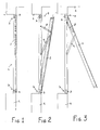
- the window or door frame construction which has been generally indicated by the reference number 1, comprises a glazed panel 2, mounted on a fixed framework 3, applied to a wall 4.
- the glazed panel 2 comprises a panel frame 5, coupled to the fixed frame 3 by bottom pivot means, allowing the glazed panel 2 to turn about its bottom horizontal side 6, as well as top pivot means allowing the glazed panel 2 to rotate about its horizontal top side 7.
- the glazed panel 2 is coupled to the fixed framework or frame 3 by two pairs of coupling levers, respectively a top coupling lever 8 and a bottom coupling lever 9.
- the rotary movement of the glazed panel 2, with respect to the bottom or top pivot means can be selectively controlled by control means for controlling the pivot means, i.e. for respectively engaging and disengaging the pivot means, alternately, by engaging the bottom pivot means and simultaneously disengaging the top pivot means.
- the top lever pair 8 will limit the opening of the glazed panel 2, as it is rotated about the bottom side 6 thereof, whereas the bottom lever pair 8 will hold the glazed panel 2 at an opened position or condition thereof, as it is rotated about the top side 7.
- each top lever 8 operates as urged by a resilient element, such as a coil spring 9, held in the side upright of the fixed frame 3, to dampen the opening of said glazed panel.
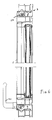
- the above mentioned control means comprises, in particular, a lever 10 which can be rotated to at least three positions, i.e.: a closed window position, an open window position, in which the window is open at the top thereof, with a wasistas type of opening pattern, and a bottom opened window position.
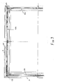
- lever 10 As the lever 10 is rotated, it will control a plurality of elongated elements, which are flexible at least at the corners of the fixed frame 3, and associated with the pivot means.
- the bottom pivot means comprise at least a pair of bottom pins 11, each associated with a respective bottom rod 12 in turn coupled to the control lever 10.
- the top pivot means comprise, in turn, at least a pair of top pivot pins 13, each of which is associated with a respective top rod 14.
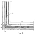
- Each said top rod 14 is associated with a corresponding side rod 15, which can slide along the upright of the fixed frame 3, through a flexible blade element 16 designed for transmitting the motion of the side rod 15 to the respective top rod 14.
- each side rod 15 is coupled to a respective bottom rod 12 by a flexible blade element 17, designed for transmitting motion from'the bottom rod 12 to the respective side rod 15.
- the control lever 10 is operatively kinematically coupled to the bottom rods 12, thereby, for each rotation of said control lever 10, the two rods 12 will be oppositely driven, i.e. either both outwardly, or both inwardly.
- the control lever 10 defines at least three operating positions: a closed window position, in which all the bottom pivot pins 11 and top pivot pins 13 engage respectively recesses formed in the frame 3 and the glazed panel 2 is closed; a position in which the window is open at the top thereof, with a wasistas type of opening pattern, in which the bottom rods are urged by the rotating lever 10 outwardly so as to cause the bottom pivot pins 11 to engage the respective recesses of the fixed frame, whereas the top pivot pins 13 are withdrawn so as to disengage the top recesses; a position in which the window is open at the bottom thereof, where the bottom pivot pins 11 are withdrawn so as to disengage their respective recesses, whereas the top pivot pins 13 engage the respective recesses of the fixed frame.
- This feature would allow to greatly reducing the exposed to the view surfaces of the wing uprights and cross members.
- the invention provides a window or door frame, specifically designed for application in buildings having large glazed surfaces, in which the downward and inward opening of the glazed panel allows to easily clean the outer surface of said glazed panel, from the inside of the building.
- the used materials, as well as the contingent size and shapes can be any, according to requirements and the status of the art.
Landscapes
- Engineering & Computer Science (AREA)
- Mechanical Engineering (AREA)
- Wing Frames And Configurations (AREA)
- Door And Window Frames Mounted To Openings (AREA)
Abstract
Description
and
Claims (14)
- A window or door frame construction, including an improved opening system, having at least an openable glazed panel, characterized in that said panel can be selectively turned either about a horizontal top side thereof or about a horizontal bottom side thereof.
- A window or door frame construction, according to Claim 1, characterized in that said glazed panel is mounted on a fixed frame coupled to a wall or to a bearing structure of the building face and comprising a frame coupled to said fixed frame by bottom pivot means, allowing said glazed panel to rotate about the horizontal bottom side thereof, and top pivot means, allowing said glazed panel to rotate about the horizontal top side thereof, said glazed panel being moreover coupled to said fixed frame by two pairs of levers, respectively a top lever pair and a bottom lever pair.
- A window or door frame construction, according to Claim 1 or 2, characterized in that the rotation of said glazed panel, with respect to said bottom or top pivot means, is selectively controlled by control means for controlling said pivot means, respectively for engaging or disengaging said pivot means, alternately, by respectively engaging said bottom pivot means and simultaneously disengaging said top pivot means, to allow said glazed panel to rotate about the bottom side thereof, or by engaging said top pivot means and simultaneously disengaging said bottom pivot means to allow said panel to rotate about the top side thereof.
- A window or door frame construction, according to one or more of the preceding claims, characterized in that said top lever pair is so designed as to limit the opening of said glazed panel as said glazed panel is rotated about the bottom side thereof, whereas the bottom lever pair holds said glazed panel in an open position thereof as said glazed panel is rotated about the top side thereof.
- A window or door frame construction, according to one or more of the preceding claims, characterized in that each said top lever operates against an urging resilient element, such as a coil spring, held in a side upright of the fixed frame, to dampen the opening of said glazed panel.
- A window or door frame construction, according to one or more of the preceding claims, characterized in that said control means comprise a lever which can be rotated to at least three positions: a closed window position, a position at which said window is opened at the top thereof, with a wasistas type of opening pattern, and a position in which said window is opened at the bottom thereof.
- A window or door frame construction, according to one or more of the preceding claims, characterized in that said control lever controls, as it is rotated, a plurality of elongated elements, which are flexible at least at the corners of said fixed frame, and being coupled to said pivot means.
- A window or door frame construction, according to one or more of the preceding claims, characterized in that said bottom pivot means comprise at least a pair of bottom pins each of which is associated with a respective bottom rod coupled to said control lever.
- A window or door frame construction, according to one or more of the preceding claims, characterized in that said top pivot means comprise at least a pair of top pins each of which is associated with a respective top rod.
- A window or door frame construction, according to one or more of the preceding claims, characterized in that each top rod is operatively coupled to a respective side rod, which can slide along the upright of the fixed frame, through a flexible blade element designed for transmitting motion from the side rod to the corresponding top rod.
- A window or door frame construction, according to one or more of the preceding claims, characterized in that each said side rod is operatively coupled to a corresponding bottom rod through a flexible blade element adapted to transmit motion from said bottom rod to said respective side rod.
- A window or door frame construction, according to one or more of the preceding claims, characterized in that said control lever is operatively kinematically coupled to said bottom rods, thereby, for each rotation of said control lever, said two rods are oppositely driven, i.e. both outwardly or both inwardly.
- A window or door frame construction, according to one or more of the preceding claims, characterized in that said control lever defines at least three operating positions: a closed window position, in which all the bottom and top pivot pins are engaged in respective recesses of said fixed frame and said glazed panel is closed; an open window position in which the window is open at the top thereof, with a wasistas type of open pattern, in which the bottom rods are outwardly urged by the rotating lever, to cause the bottom pivot pins to engage their respective recesses of said fixed frame, said top pivot pins being withdrawn so as to disengage the top recesses therefor; an open window position, in which the window is open at the bottom thereof, where the bottom pivot pins are withdrawn thereby disengaging their respective recesses, whereas the top pivot pins engage their respective recesses in said fixed frame.
- A window or door frame construction, according to one or more of the preceding claims, characterized in that said it comprises one or more of the disclosed and/or illustrated characteristics.
Applications Claiming Priority (2)
| Application Number | Priority Date | Filing Date | Title |
|---|---|---|---|
| ITMI20022226 | 2002-10-18 | ||
| ITMI20022226 ITMI20022226A1 (en) | 2002-10-18 | 2002-10-18 | WINDOW FRAME, ESPECIALLY FOR CONTINUOUS GLASS BUILDINGS, EQUIPPED WITH A PERFECTED OPENING SYSTEM |
Publications (2)
| Publication Number | Publication Date |
|---|---|
| EP1411202A2 true EP1411202A2 (en) | 2004-04-21 |
| EP1411202A3 EP1411202A3 (en) | 2006-03-15 |
Family
ID=32040272
Family Applications (1)
| Application Number | Title | Priority Date | Filing Date |
|---|---|---|---|
| EP02026073A Withdrawn EP1411202A3 (en) | 2002-10-18 | 2002-11-22 | Window or door frame construction for continuous-glazing buildings, including an improved opening system |
Country Status (2)
| Country | Link |
|---|---|
| EP (1) | EP1411202A3 (en) |
| IT (1) | ITMI20022226A1 (en) |
Cited By (1)
| Publication number | Priority date | Publication date | Assignee | Title |
|---|---|---|---|---|
| WO2015147722A1 (en) | 2014-03-28 | 2015-10-01 | Hans Öhman | Mechanism at pivoting window |
Family Cites Families (3)
| Publication number | Priority date | Publication date | Assignee | Title |
|---|---|---|---|---|
| GB1182394A (en) * | 1967-05-26 | 1970-02-25 | Wonder Door Holdings Ltd | Improvements in or relating to Closures |
| GB1350844A (en) * | 1971-11-05 | 1974-04-24 | Hallam Sleigh Cheston Ltd | Roof ventilator or roof hatch assemblies for vehicles |
| DE19603770A1 (en) * | 1996-02-02 | 1997-08-07 | Winkhaus Fa August | Window, door or the like with a fitting system |
-
2002
- 2002-10-18 IT ITMI20022226 patent/ITMI20022226A1/en unknown
- 2002-11-22 EP EP02026073A patent/EP1411202A3/en not_active Withdrawn
Cited By (2)
| Publication number | Priority date | Publication date | Assignee | Title |
|---|---|---|---|---|
| WO2015147722A1 (en) | 2014-03-28 | 2015-10-01 | Hans Öhman | Mechanism at pivoting window |
| EP3122974A4 (en) * | 2014-03-28 | 2017-11-29 | Hans Öhman | Mechanism at pivoting window |
Also Published As
| Publication number | Publication date |
|---|---|
| ITMI20022226A1 (en) | 2004-04-19 |
| EP1411202A3 (en) | 2006-03-15 |
Similar Documents
| Publication | Publication Date | Title |
|---|---|---|
| US4274469A (en) | Operator for a slat shade assembly | |
| US3911621A (en) | Multi-purpose window | |
| AU2017202404A1 (en) | A Twin Louvre Window Assembly for Efficient Thermal Control | |
| EP0510855B1 (en) | Sealing device for doors | |
| CN1853025B (en) | An improved pivot window with retardarce device | |
| CN213116038U (en) | Fire rescue window capable of being opened both indoors and outdoors | |
| CA3049323A1 (en) | Insulated door | |
| US3936978A (en) | Window having a bellows-type opening movement and permitting complete reversal of the window-leaf | |
| JP7510898B2 (en) | Natural ventilation window system | |
| EP1334253B1 (en) | Window construction having several ways of opening | |
| CN211314018U (en) | Electric anti-theft window with inner and outer opening | |
| US772686A (en) | Sliding and swinging sash-window. | |
| CN209212101U (en) | A kind of installation system and door and window | |
| JP2913587B1 (en) | Indoor / outdoor pressure difference elimination device for doors of buildings, etc. | |
| JPH09303052A (en) | Opening and closing window used for curtain wall | |
| JP2000282729A (en) | Controller of tilting window | |
| JP4375936B2 (en) | Locking device for emergency entrance door of high-rise building | |
| CN217760739U (en) | Novel aluminum alloy energy-saving fireproof window made of materials | |
| SU1506055A1 (en) | Arrangement for protecting exposed openings of buildings | |
| JPH0616060Y2 (en) | Auxiliary lock for louver sash | |
| JPS6212797Y2 (en) | ||
| AU2020233619A1 (en) | A lock assembly for a window | |
| JPH0246614Y2 (en) | ||
| JPH0328689Y2 (en) | ||
| CN211473900U (en) | Integrated door and window |
Legal Events
| Date | Code | Title | Description |
|---|---|---|---|
| PUAI | Public reference made under article 153(3) epc to a published international application that has entered the european phase |
Free format text: ORIGINAL CODE: 0009012 |
|
| AK | Designated contracting states |
Kind code of ref document: A2 Designated state(s): AT BE BG CH CY CZ DE DK EE ES FI FR GB GR IE IT LI LU MC NL PT SE SK TR |
|
| AX | Request for extension of the european patent |
Extension state: AL LT LV MK RO SI |
|
| PUAL | Search report despatched |
Free format text: ORIGINAL CODE: 0009013 |
|
| AK | Designated contracting states |
Kind code of ref document: A3 Designated state(s): AT BE BG CH CY CZ DE DK EE ES FI FR GB GR IE IT LI LU MC NL PT SE SK TR |
|
| AX | Request for extension of the european patent |
Extension state: AL LT LV MK RO SI |
|
| RIC1 | Information provided on ipc code assigned before grant |
Ipc: E05D 15/52 20060101ALI20060120BHEP Ipc: E05D 15/50 20060101AFI20040211BHEP |
|
| 17P | Request for examination filed |
Effective date: 20060802 |
|
| AKX | Designation fees paid |
Designated state(s): AT BE BG CH CY CZ DE DK EE ES FI FR GB GR IE IT LI LU MC NL PT SE SK TR |
|
| STAA | Information on the status of an ep patent application or granted ep patent |
Free format text: STATUS: THE APPLICATION IS DEEMED TO BE WITHDRAWN |
|
| 18D | Application deemed to be withdrawn |
Effective date: 20080603 |