EP1411241A2 - Stabförmige Zündspule - Google Patents
Stabförmige Zündspule Download PDFInfo
- Publication number
- EP1411241A2 EP1411241A2 EP03022889A EP03022889A EP1411241A2 EP 1411241 A2 EP1411241 A2 EP 1411241A2 EP 03022889 A EP03022889 A EP 03022889A EP 03022889 A EP03022889 A EP 03022889A EP 1411241 A2 EP1411241 A2 EP 1411241A2
- Authority
- EP
- European Patent Office
- Prior art keywords
- ignition coil
- primary
- core
- layer
- coil body
- Prior art date
- Legal status (The legal status is an assumption and is not a legal conclusion. Google has not performed a legal analysis and makes no representation as to the accuracy of the status listed.)
- Granted
Links
Images

Classifications
-
- F—MECHANICAL ENGINEERING; LIGHTING; HEATING; WEAPONS; BLASTING
- F02—COMBUSTION ENGINES; HOT-GAS OR COMBUSTION-PRODUCT ENGINE PLANTS
- F02P—IGNITION, OTHER THAN COMPRESSION IGNITION, FOR INTERNAL-COMBUSTION ENGINES; TESTING OF IGNITION TIMING IN COMPRESSION-IGNITION ENGINES
- F02P3/00—Other installations
- F02P3/02—Other installations having inductive energy storage, e.g. arrangements of induction coils
Definitions
- Such a rod-shaped ignition coil is from DE 4208706 C2 known.
- the core has an angular outer surface on the stacked metal sheets which can lead to extreme field concentrations that Operation of the ignition coil can lead to failures.
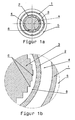
- FIG. 1a and 1b includes a conventional rod-shaped ignition coil, not shown Ignition coil housing, in which a primary coil body 2, the outside carries a primary winding 4 and in which an approximately cylindrical core 3 made of stacked for example rectangular metal sheets arranged in a potting compound 8 and a surrounding the primary coil bobbin 2
- Secondary coil former 1, which carries a secondary winding 5, being between the ignition coil housing and not shown a potting compound is provided on the outside of the secondary winding 5 which is also not shown.
- the primary coil body can with its primary winding outside the Secondary winding body arranged with its secondary winding be, so in this case the core of the secondary winding body is surrounded.
- Figs. 2a and 2b is at the embodiment of the ignition coil according to the invention Shielding high field concentrations at the edges 6 the sheets of the core 3 occur and breakdowns in the Can lead coil, the inner cylinder surface of the primary coil body 2 with a metallic conductive coating 7 provided in particular from nickel.
- Fig. 2b the structure of the illustrated Embodiment of the ignition coil according to the invention thus from the inside out the cylindrical core 3, one Air gap, the coating 7 on the primary coil former 2, the primary coil body 2, the primary winding 4, the secondary coil body 1, the secondary winding 5, the potting compound and the housing, the latter not being shown.
- the metallic coating preferably has one or more interruptions in the axial direction.
- the coating gap should be chosen so that at the coating gap after installing the ignition coil no field-concentrating edge of the core 3 runs.
- the training according to the invention can be seen
- the advantage of preventing electrical breakdowns can, a much lower for the coating Space is required than when using a potting compound or additional film is the case. Since no additional Component such as an additional film provided assembly is simplified, the result is shorter Assembly times. The curing times of the potting material there is also no need.
Landscapes
- Engineering & Computer Science (AREA)
- Chemical & Material Sciences (AREA)
- Combustion & Propulsion (AREA)
- Mechanical Engineering (AREA)
- General Engineering & Computer Science (AREA)
- Ignition Installations For Internal Combustion Engines (AREA)
Abstract
Description
Claims (8)
- Stabförmige Zündspule mitdadurch gekennzeichnet, dass die innere Zylinderfläche des den Kern umgebenden Spulenkörpers metallisch beschichtet ist.einem zylindrischen Primärspulenkörper, der eine Primärwicklung trägt, einem annähernd zylindrischen Kern aus gestapelten Metallblechen, undeinem Sekundärspulenkörper, der eine Sekundärwicklung trägt,
- Zündspule nach Anspruch 1, dadurch gekennzeichnet, dass der Primärspulenkörper innenliegend und der Sekundärspulenkörper außenliegend angeordnet sind, und die innere, dem Kern zuwandte Zylinderfläche des Primärspulenkörpers metallisch beschichtet ist.
- Zündspule nach Anspruch 1, dadurch gekennzeichnet, dass der Primärspulenkörper außenliegend und der Sekundärspulenkörper innenliegend angeordnet sind, und die innere, dem Kern zugewandte Zylinderfläche des Sekundärspulenkörpers metallisch beschichtet ist.
- Zündspule nach Anspruch 1, 2 oder 3 dadurch gekennzeichnet, dass die metallische Beschichtung eine Stärke von 100 bis 200 µm hat.
- Zündspule nach einem der Ansprüche 1 bis 4, dadurch gekennzeichnet, dass die metallische Beschichtung mit Unterbrechungen in axialer Richtung ausgebildet ist.
- Zündspule nach Anspruch 5, dadurch gekennzeichnet, dass die Unterbrechungen so positioniert sind, dass an den Beschichtungslücken keine Blechkante des Kerns verläuft.
- Zündspule nach Anspruch 1, 2 oder 3 dadurch gekennzeichnet, dass die metallische Beschichtung mehrlagig ausgebildet ist, wobei die erste Lage mehr als 180° und weniger als 360°, vorzugsweise 270° des Innenumfangs des Sekundärspulenkörpers überdeckt, darauf eine Isolierschicht vorgesehen ist, die den gesamten Innenumfang des Sekundärspulenkörpers überdeckt, und auf der Isolierschicht eine zweite Lage ausgebildet ist, die mit Überlappung der ersten Lage den von der ersten Lage nicht überdeckten Bereich abdeckt.
- Zündspule nach einem der vorhergehenden Ansprüche, dadurch gekennzeichnet, dass die metallische Beschichtung mit einer Schutzschicht abgedeckt ist.
Applications Claiming Priority (2)
| Application Number | Priority Date | Filing Date | Title |
|---|---|---|---|
| DE10248520 | 2002-10-17 | ||
| DE10248520A DE10248520B3 (de) | 2002-10-17 | 2002-10-17 | Stabförmige Zündspule |
Publications (3)
| Publication Number | Publication Date |
|---|---|
| EP1411241A2 true EP1411241A2 (de) | 2004-04-21 |
| EP1411241A3 EP1411241A3 (de) | 2006-03-22 |
| EP1411241B1 EP1411241B1 (de) | 2007-02-14 |
Family
ID=32038743
Family Applications (1)
| Application Number | Title | Priority Date | Filing Date |
|---|---|---|---|
| EP03022889A Expired - Lifetime EP1411241B1 (de) | 2002-10-17 | 2003-10-08 | Stabförmige Zündspule |
Country Status (3)
| Country | Link |
|---|---|
| EP (1) | EP1411241B1 (de) |
| AT (1) | ATE354021T1 (de) |
| DE (2) | DE10248520B3 (de) |
Families Citing this family (2)
| Publication number | Priority date | Publication date | Assignee | Title |
|---|---|---|---|---|
| DE102005037257A1 (de) * | 2005-08-08 | 2007-02-15 | Robert Bosch Gmbh | Stabzündspule für eine Zündanlage |
| DE102006019296A1 (de) * | 2006-04-26 | 2007-10-31 | Robert Bosch Gmbh | Zündspule, insbesondere für eine Brennkraftmaschine eines Kraftfahrzeugs |
Family Cites Families (4)
| Publication number | Priority date | Publication date | Assignee | Title |
|---|---|---|---|---|
| DE4208706C2 (de) * | 1992-03-18 | 1996-11-28 | Beru Werk Ruprecht Gmbh Co A | Zündspule für eine Zündanlage einer Brennkraftmaschine |
| DE19702438C2 (de) * | 1997-01-24 | 1999-05-06 | Bremicker Auto Elektrik | Stabzündspule für Brennkraftmaschinen |
| FR2778490B1 (fr) * | 1998-05-11 | 2000-07-28 | Sagem | Bobine d'allumage pour moteur a combustion interne |
| DE19962279C2 (de) * | 1999-01-19 | 2003-04-30 | Bremi Auto Elek K Ernst Bremic | Zündspule |
-
2002
- 2002-10-17 DE DE10248520A patent/DE10248520B3/de not_active Expired - Fee Related
-
2003
- 2003-10-08 EP EP03022889A patent/EP1411241B1/de not_active Expired - Lifetime
- 2003-10-08 DE DE50306480T patent/DE50306480D1/de not_active Expired - Lifetime
- 2003-10-08 AT AT03022889T patent/ATE354021T1/de not_active IP Right Cessation
Also Published As
| Publication number | Publication date |
|---|---|
| DE10248520B3 (de) | 2004-05-13 |
| ATE354021T1 (de) | 2007-03-15 |
| EP1411241A3 (de) | 2006-03-22 |
| DE50306480D1 (de) | 2007-03-29 |
| EP1411241B1 (de) | 2007-02-14 |
Similar Documents
| Publication | Publication Date | Title |
|---|---|---|
| DE4201937C2 (de) | Piezoelektrisches laminiertes Stellglied | |
| EP0112482B1 (de) | Wicklungsanordnung für Trockentransformatoren | |
| DE69207465T2 (de) | Montage elektronischer Bauteile auf Substrate | |
| DE69112186T2 (de) | Induktive Anordnung mit einem Ringformkern. | |
| DE69904045T2 (de) | Spulenkörper für transformator | |
| DE19838587B4 (de) | Induktivität und Verfahren zum Herstellen eines Induktivität | |
| DE10112460B4 (de) | Mehrschicht-Induktivität | |
| DE60113459T2 (de) | Spulenfilter und verfahren zu seiner herstellung | |
| DE69811459T2 (de) | Chip Kügelchen und Herstellungsverfahren | |
| DE102009028629A9 (de) | Ultra-Breitband-Kondensator | |
| DE2952441A1 (de) | Laminiertes elektronisches bauteil und verfahren zur herstellung solcher bauteile | |
| DE102019212193A1 (de) | Spulenkomponente | |
| DE68908234T2 (de) | Integrierter Kondensator und Spulen/Transformatoren mit isoliertem, amorphem Metallband. | |
| DE102019208658A1 (de) | Spulenkomponente | |
| DE10157590A1 (de) | Wicklung für einen Transformator oder eine Spule | |
| DE1292744B (de) | Hochspannungswicklung fuer Transformatoren und Drosselspulen | |
| DE102023129344A1 (de) | Spulenbauteil | |
| DE3909528A1 (de) | Stoerschutzfilter | |
| EP1411241B1 (de) | Stabförmige Zündspule | |
| DE102018210674A1 (de) | Induktives element und lc-filter | |
| EP1880399B1 (de) | Elektrisches durchführungsbauelement | |
| DD290738A5 (de) | Sende- und/oder empfangsspule aus mehrebenenleiterplatte | |
| DE102022202098B4 (de) | Spulenkomponente | |
| DE2830961C3 (de) | Funk-Entstörkondensator | |
| DE4311126C2 (de) | Stromkompensierte Mehrfachdrossel in Kompaktbauweise |
Legal Events
| Date | Code | Title | Description |
|---|---|---|---|
| PUAI | Public reference made under article 153(3) epc to a published international application that has entered the european phase |
Free format text: ORIGINAL CODE: 0009012 |
|
| AK | Designated contracting states |
Kind code of ref document: A2 Designated state(s): AT BE BG CH CY CZ DE DK EE ES FI FR GB GR HU IE IT LI LU MC NL PT RO SE SI SK TR |
|
| AX | Request for extension of the european patent |
Extension state: AL LT LV MK |
|
| PUAL | Search report despatched |
Free format text: ORIGINAL CODE: 0009013 |
|
| AK | Designated contracting states |
Kind code of ref document: A3 Designated state(s): AT BE BG CH CY CZ DE DK EE ES FI FR GB GR HU IE IT LI LU MC NL PT RO SE SI SK TR |
|
| AX | Request for extension of the european patent |
Extension state: AL LT LV MK |
|
| 17P | Request for examination filed |
Effective date: 20060407 |
|
| GRAP | Despatch of communication of intention to grant a patent |
Free format text: ORIGINAL CODE: EPIDOSNIGR1 |
|
| AKX | Designation fees paid |
Designated state(s): AT BE BG CH CY CZ DE DK EE ES FI FR GB GR HU IE IT LI LU MC NL PT RO SE SI SK TR |
|
| GRAS | Grant fee paid |
Free format text: ORIGINAL CODE: EPIDOSNIGR3 |
|
| GRAA | (expected) grant |
Free format text: ORIGINAL CODE: 0009210 |
|
| AK | Designated contracting states |
Kind code of ref document: B1 Designated state(s): AT BE BG CH CY CZ DE DK EE ES FI FR GB GR HU IE IT LI LU MC NL PT RO SE SI SK TR |
|
| PG25 | Lapsed in a contracting state [announced via postgrant information from national office to epo] |
Ref country code: FI Free format text: LAPSE BECAUSE OF FAILURE TO SUBMIT A TRANSLATION OF THE DESCRIPTION OR TO PAY THE FEE WITHIN THE PRESCRIBED TIME-LIMIT Effective date: 20070214 Ref country code: SI Free format text: LAPSE BECAUSE OF FAILURE TO SUBMIT A TRANSLATION OF THE DESCRIPTION OR TO PAY THE FEE WITHIN THE PRESCRIBED TIME-LIMIT Effective date: 20070214 Ref country code: IE Free format text: LAPSE BECAUSE OF FAILURE TO SUBMIT A TRANSLATION OF THE DESCRIPTION OR TO PAY THE FEE WITHIN THE PRESCRIBED TIME-LIMIT Effective date: 20070214 Ref country code: DK Free format text: LAPSE BECAUSE OF FAILURE TO SUBMIT A TRANSLATION OF THE DESCRIPTION OR TO PAY THE FEE WITHIN THE PRESCRIBED TIME-LIMIT Effective date: 20070214 Ref country code: NL Free format text: LAPSE BECAUSE OF FAILURE TO SUBMIT A TRANSLATION OF THE DESCRIPTION OR TO PAY THE FEE WITHIN THE PRESCRIBED TIME-LIMIT Effective date: 20070214 |
|
| REG | Reference to a national code |
Ref country code: GB Ref legal event code: FG4D Free format text: NOT ENGLISH |
|
| REG | Reference to a national code |
Ref country code: CH Ref legal event code: EP |
|
| REF | Corresponds to: |
Ref document number: 50306480 Country of ref document: DE Date of ref document: 20070329 Kind code of ref document: P |
|
| REG | Reference to a national code |
Ref country code: IE Ref legal event code: FG4D Free format text: LANGUAGE OF EP DOCUMENT: GERMAN |
|
| PG25 | Lapsed in a contracting state [announced via postgrant information from national office to epo] |
Ref country code: SE Free format text: LAPSE BECAUSE OF FAILURE TO SUBMIT A TRANSLATION OF THE DESCRIPTION OR TO PAY THE FEE WITHIN THE PRESCRIBED TIME-LIMIT Effective date: 20070514 |
|
| PG25 | Lapsed in a contracting state [announced via postgrant information from national office to epo] |
Ref country code: BG Free format text: LAPSE BECAUSE OF EXPIRATION OF PROTECTION Effective date: 20070515 |
|
| PG25 | Lapsed in a contracting state [announced via postgrant information from national office to epo] |
Ref country code: ES Free format text: LAPSE BECAUSE OF FAILURE TO SUBMIT A TRANSLATION OF THE DESCRIPTION OR TO PAY THE FEE WITHIN THE PRESCRIBED TIME-LIMIT Effective date: 20070525 |
|
| ET | Fr: translation filed | ||
| PG25 | Lapsed in a contracting state [announced via postgrant information from national office to epo] |
Ref country code: PT Free format text: LAPSE BECAUSE OF FAILURE TO SUBMIT A TRANSLATION OF THE DESCRIPTION OR TO PAY THE FEE WITHIN THE PRESCRIBED TIME-LIMIT Effective date: 20070716 |
|
| NLV1 | Nl: lapsed or annulled due to failure to fulfill the requirements of art. 29p and 29m of the patents act | ||
| GBV | Gb: ep patent (uk) treated as always having been void in accordance with gb section 77(7)/1977 [no translation filed] |
Effective date: 20070214 |
|
| REG | Reference to a national code |
Ref country code: IE Ref legal event code: FD4D |
|
| PG25 | Lapsed in a contracting state [announced via postgrant information from national office to epo] |
Ref country code: SK Free format text: LAPSE BECAUSE OF FAILURE TO SUBMIT A TRANSLATION OF THE DESCRIPTION OR TO PAY THE FEE WITHIN THE PRESCRIBED TIME-LIMIT Effective date: 20070214 Ref country code: GB Free format text: LAPSE BECAUSE OF FAILURE TO SUBMIT A TRANSLATION OF THE DESCRIPTION OR TO PAY THE FEE WITHIN THE PRESCRIBED TIME-LIMIT Effective date: 20070214 |
|
| PLBE | No opposition filed within time limit |
Free format text: ORIGINAL CODE: 0009261 |
|
| STAA | Information on the status of an ep patent application or granted ep patent |
Free format text: STATUS: NO OPPOSITION FILED WITHIN TIME LIMIT |
|
| PG25 | Lapsed in a contracting state [announced via postgrant information from national office to epo] |
Ref country code: CZ Free format text: LAPSE BECAUSE OF FAILURE TO SUBMIT A TRANSLATION OF THE DESCRIPTION OR TO PAY THE FEE WITHIN THE PRESCRIBED TIME-LIMIT Effective date: 20070214 Ref country code: RO Free format text: LAPSE BECAUSE OF FAILURE TO SUBMIT A TRANSLATION OF THE DESCRIPTION OR TO PAY THE FEE WITHIN THE PRESCRIBED TIME-LIMIT Effective date: 20070214 |
|
| 26N | No opposition filed |
Effective date: 20071115 |
|
| BERE | Be: lapsed |
Owner name: BERU A.G. Effective date: 20071031 |
|
| PG25 | Lapsed in a contracting state [announced via postgrant information from national office to epo] |
Ref country code: GR Free format text: LAPSE BECAUSE OF FAILURE TO SUBMIT A TRANSLATION OF THE DESCRIPTION OR TO PAY THE FEE WITHIN THE PRESCRIBED TIME-LIMIT Effective date: 20070515 |
|
| PG25 | Lapsed in a contracting state [announced via postgrant information from national office to epo] |
Ref country code: MC Free format text: LAPSE BECAUSE OF NON-PAYMENT OF DUE FEES Effective date: 20071031 |
|
| REG | Reference to a national code |
Ref country code: CH Ref legal event code: PL |
|
| PG25 | Lapsed in a contracting state [announced via postgrant information from national office to epo] |
Ref country code: LI Free format text: LAPSE BECAUSE OF NON-PAYMENT OF DUE FEES Effective date: 20071031 Ref country code: CH Free format text: LAPSE BECAUSE OF NON-PAYMENT OF DUE FEES Effective date: 20071031 |
|
| PG25 | Lapsed in a contracting state [announced via postgrant information from national office to epo] |
Ref country code: BE Free format text: LAPSE BECAUSE OF NON-PAYMENT OF DUE FEES Effective date: 20071031 |
|
| PG25 | Lapsed in a contracting state [announced via postgrant information from national office to epo] |
Ref country code: EE Free format text: LAPSE BECAUSE OF FAILURE TO SUBMIT A TRANSLATION OF THE DESCRIPTION OR TO PAY THE FEE WITHIN THE PRESCRIBED TIME-LIMIT Effective date: 20070214 |
|
| PG25 | Lapsed in a contracting state [announced via postgrant information from national office to epo] |
Ref country code: CY Free format text: LAPSE BECAUSE OF FAILURE TO SUBMIT A TRANSLATION OF THE DESCRIPTION OR TO PAY THE FEE WITHIN THE PRESCRIBED TIME-LIMIT Effective date: 20070214 |
|
| PG25 | Lapsed in a contracting state [announced via postgrant information from national office to epo] |
Ref country code: LU Free format text: LAPSE BECAUSE OF NON-PAYMENT OF DUE FEES Effective date: 20071008 |
|
| PG25 | Lapsed in a contracting state [announced via postgrant information from national office to epo] |
Ref country code: HU Free format text: LAPSE BECAUSE OF FAILURE TO SUBMIT A TRANSLATION OF THE DESCRIPTION OR TO PAY THE FEE WITHIN THE PRESCRIBED TIME-LIMIT Effective date: 20070815 Ref country code: TR Free format text: LAPSE BECAUSE OF FAILURE TO SUBMIT A TRANSLATION OF THE DESCRIPTION OR TO PAY THE FEE WITHIN THE PRESCRIBED TIME-LIMIT Effective date: 20070214 |
|
| PGFP | Annual fee paid to national office [announced via postgrant information from national office to epo] |
Ref country code: AT Payment date: 20091009 Year of fee payment: 7 Ref country code: DE Payment date: 20091030 Year of fee payment: 7 |
|
| PGFP | Annual fee paid to national office [announced via postgrant information from national office to epo] |
Ref country code: FR Payment date: 20091026 Year of fee payment: 7 Ref country code: IT Payment date: 20091021 Year of fee payment: 7 |
|
| PG25 | Lapsed in a contracting state [announced via postgrant information from national office to epo] |
Ref country code: FR Free format text: LAPSE BECAUSE OF NON-PAYMENT OF DUE FEES Effective date: 20101102 |
|
| REG | Reference to a national code |
Ref country code: FR Ref legal event code: ST Effective date: 20110630 |
|
| PG25 | Lapsed in a contracting state [announced via postgrant information from national office to epo] |
Ref country code: AT Free format text: LAPSE BECAUSE OF NON-PAYMENT OF DUE FEES Effective date: 20101008 |
|
| REG | Reference to a national code |
Ref country code: DE Ref legal event code: R119 Ref document number: 50306480 Country of ref document: DE Effective date: 20110502 |
|
| PG25 | Lapsed in a contracting state [announced via postgrant information from national office to epo] |
Ref country code: IT Free format text: LAPSE BECAUSE OF NON-PAYMENT OF DUE FEES Effective date: 20101008 |
|
| PG25 | Lapsed in a contracting state [announced via postgrant information from national office to epo] |
Ref country code: DE Free format text: LAPSE BECAUSE OF NON-PAYMENT OF DUE FEES Effective date: 20110502 |