EP1411256A1 - Plateau d'appui dans un dispositif à disques - Google Patents
Plateau d'appui dans un dispositif à disques Download PDFInfo
- Publication number
- EP1411256A1 EP1411256A1 EP20020023324 EP02023324A EP1411256A1 EP 1411256 A1 EP1411256 A1 EP 1411256A1 EP 20020023324 EP20020023324 EP 20020023324 EP 02023324 A EP02023324 A EP 02023324A EP 1411256 A1 EP1411256 A1 EP 1411256A1
- Authority
- EP
- European Patent Office
- Prior art keywords
- backing
- plate
- disk
- backing plate
- shell
- Prior art date
- Legal status (The legal status is an assumption and is not a legal conclusion. Google has not performed a legal analysis and makes no representation as to the accuracy of the status listed.)
- Granted
Links
- 206010043183 Teething Diseases 0.000 claims description 37
- 230000036346 tooth eruption Effects 0.000 claims description 37
- 239000002184 metal Substances 0.000 claims description 8
- 238000003754 machining Methods 0.000 claims 1
- 229910000831 Steel Inorganic materials 0.000 description 31
- 239000010959 steel Substances 0.000 description 31
- 230000005540 biological transmission Effects 0.000 description 5
- 238000010276 construction Methods 0.000 description 5
- 238000004519 manufacturing process Methods 0.000 description 5
- 238000000034 method Methods 0.000 description 5
- 230000008901 benefit Effects 0.000 description 2
- 230000008569 process Effects 0.000 description 2
- 238000004364 calculation method Methods 0.000 description 1
- 230000008878 coupling Effects 0.000 description 1
- 238000010168 coupling process Methods 0.000 description 1
- 238000005859 coupling reaction Methods 0.000 description 1
- 230000001419 dependent effect Effects 0.000 description 1
- 238000011161 development Methods 0.000 description 1
- 230000018109 developmental process Effects 0.000 description 1
- 238000006073 displacement reaction Methods 0.000 description 1
- 238000012821 model calculation Methods 0.000 description 1
- 230000002265 prevention Effects 0.000 description 1
- 230000003014 reinforcing effect Effects 0.000 description 1
- 238000005245 sintering Methods 0.000 description 1
- 230000000087 stabilizing effect Effects 0.000 description 1
- 238000010792 warming Methods 0.000 description 1
- 239000013585 weight reducing agent Substances 0.000 description 1
Images


Classifications
-
- F—MECHANICAL ENGINEERING; LIGHTING; HEATING; WEAPONS; BLASTING
- F16—ENGINEERING ELEMENTS AND UNITS; GENERAL MEASURES FOR PRODUCING AND MAINTAINING EFFECTIVE FUNCTIONING OF MACHINES OR INSTALLATIONS; THERMAL INSULATION IN GENERAL
- F16D—COUPLINGS FOR TRANSMITTING ROTATION; CLUTCHES; BRAKES
- F16D13/00—Friction clutches
- F16D13/58—Details
-
- F—MECHANICAL ENGINEERING; LIGHTING; HEATING; WEAPONS; BLASTING
- F16—ENGINEERING ELEMENTS AND UNITS; GENERAL MEASURES FOR PRODUCING AND MAINTAINING EFFECTIVE FUNCTIONING OF MACHINES OR INSTALLATIONS; THERMAL INSULATION IN GENERAL
- F16D—COUPLINGS FOR TRANSMITTING ROTATION; CLUTCHES; BRAKES
- F16D65/00—Parts or details
- F16D65/02—Braking members; Mounting thereof
- F16D65/12—Discs; Drums for disc brakes
-
- F—MECHANICAL ENGINEERING; LIGHTING; HEATING; WEAPONS; BLASTING
- F16—ENGINEERING ELEMENTS AND UNITS; GENERAL MEASURES FOR PRODUCING AND MAINTAINING EFFECTIVE FUNCTIONING OF MACHINES OR INSTALLATIONS; THERMAL INSULATION IN GENERAL
- F16D—COUPLINGS FOR TRANSMITTING ROTATION; CLUTCHES; BRAKES
- F16D13/00—Friction clutches
- F16D13/58—Details
- F16D13/60—Clutching elements
- F16D13/64—Clutch-plates; Clutch-lamellae
- F16D13/648—Clutch-plates; Clutch-lamellae for clutches with multiple lamellae
-
- F—MECHANICAL ENGINEERING; LIGHTING; HEATING; WEAPONS; BLASTING
- F16—ENGINEERING ELEMENTS AND UNITS; GENERAL MEASURES FOR PRODUCING AND MAINTAINING EFFECTIVE FUNCTIONING OF MACHINES OR INSTALLATIONS; THERMAL INSULATION IN GENERAL
- F16D—COUPLINGS FOR TRANSMITTING ROTATION; CLUTCHES; BRAKES
- F16D13/00—Friction clutches
- F16D13/58—Details
- F16D13/70—Pressure members, e.g. pressure plates, for clutch-plates or lamellae; Guiding arrangements for pressure members
-
- F—MECHANICAL ENGINEERING; LIGHTING; HEATING; WEAPONS; BLASTING
- F16—ENGINEERING ELEMENTS AND UNITS; GENERAL MEASURES FOR PRODUCING AND MAINTAINING EFFECTIVE FUNCTIONING OF MACHINES OR INSTALLATIONS; THERMAL INSULATION IN GENERAL
- F16D—COUPLINGS FOR TRANSMITTING ROTATION; CLUTCHES; BRAKES
- F16D25/00—Fluid-actuated clutches
- F16D25/12—Details not specific to one of the before-mentioned types
-
- F—MECHANICAL ENGINEERING; LIGHTING; HEATING; WEAPONS; BLASTING
- F16—ENGINEERING ELEMENTS AND UNITS; GENERAL MEASURES FOR PRODUCING AND MAINTAINING EFFECTIVE FUNCTIONING OF MACHINES OR INSTALLATIONS; THERMAL INSULATION IN GENERAL
- F16D—COUPLINGS FOR TRANSMITTING ROTATION; CLUTCHES; BRAKES
- F16D65/00—Parts or details
- F16D65/02—Braking members; Mounting thereof
- F16D65/04—Bands, shoes or pads; Pivots or supporting members therefor
- F16D65/092—Bands, shoes or pads; Pivots or supporting members therefor for axially-engaging brakes, e.g. disc brakes
-
- F—MECHANICAL ENGINEERING; LIGHTING; HEATING; WEAPONS; BLASTING
- F16—ENGINEERING ELEMENTS AND UNITS; GENERAL MEASURES FOR PRODUCING AND MAINTAINING EFFECTIVE FUNCTIONING OF MACHINES OR INSTALLATIONS; THERMAL INSULATION IN GENERAL
- F16D—COUPLINGS FOR TRANSMITTING ROTATION; CLUTCHES; BRAKES
- F16D13/00—Friction clutches
- F16D13/22—Friction clutches with axially-movable clutching members
- F16D13/38—Friction clutches with axially-movable clutching members with flat clutching surfaces, e.g. discs
- F16D13/52—Clutches with multiple lamellae ; Clutches in which three or more axially moveable members are fixed alternately to the shafts to be coupled and are pressed from one side towards an axially-located member
-
- F—MECHANICAL ENGINEERING; LIGHTING; HEATING; WEAPONS; BLASTING
- F16—ENGINEERING ELEMENTS AND UNITS; GENERAL MEASURES FOR PRODUCING AND MAINTAINING EFFECTIVE FUNCTIONING OF MACHINES OR INSTALLATIONS; THERMAL INSULATION IN GENERAL
- F16D—COUPLINGS FOR TRANSMITTING ROTATION; CLUTCHES; BRAKES
- F16D65/00—Parts or details
- F16D65/02—Braking members; Mounting thereof
- F16D2065/13—Parts or details of discs or drums
- F16D2065/1304—Structure
- F16D2065/132—Structure layered
Definitions
- the invention concerns a backing plate for a disk assembly of a force transmitting aggregate, in particular a multi-disk wet clutch or a multi-disk wet brake system, according to the precharacterizing portion of Claim 1.
- the thermal load and the axial deflection of a backing plate subjected to surface pressure must, for functional reasons, be maintained as low as possible.
- the backing plates are designed to be extremely thick, as can be clearly seen for example in Fig. 2. This measure, on the one hand, increases the difficulty of manufacture of such backing plates, and on the other hand, significantly increases the weight thereof.
- the invention is thus concerned with the task of providing a backing plate which exhibits a high stiffness for prevention of deflection of the multi-disk aggregate, while at the same time being significantly reduced in weight.
- the inventive backing plate is characterized thereby, that it comprises a core plate and a backing shell.
- Core plate and backing shell are essentially ring or annular shaped as is conventional for backing plates according to the state of the art.
- the novel backing shell is similar to the conventional backing plate in design, it has however a substantially smaller construction component thickness.
- this inventive backing shell is provided with a profile design commensurate with the operating requirements. Since the backing shell may, due to this profiling, not satisfy the above described core plate or support function (carrying of a friction lining or providing a friction layer), a core plate is provided with one side flush against the backing shell (and preferably fixed against rotation).
- the backing shell could lie with play radially inside or, as the case may be, outside at the outer diameter, against the internal teeth of the disk core plate (housing) (radial fixing or locking into position).
- the above-mentioned tasks - stiffening and carrying - are basically accomplished in the inventive embodiment by different construction components (differential construction).
- the core plate is a disk of already known type.
- the disk is a known type with a friction lining provided on one side, a so-called single-side friction plate.
- This is preferably constructed identically to the other friction plates and connected to the backing shell in series in the aggregate.
- these core plate disk and the friction plate preferably exhibit identical thickness.
- the core plate on its surface opposite the backing shell carries a friction lining. It is however also possible, that the core plate is not provided with a friction lining and essentially exhibits a friction surface as e.g. shown in Fig. 1c.
- the backing shell is (preferably also) in the form of a disk.
- the advantage is comprised therein, that in accordance therewith almost all construction components of the disk assembly can be produced in a uniform manufacturing process.
- the backing shell need merely essentially be provided with an appropriate profiling.
- a rotation work process preferred however for achievement of high production volumes are the stamping and deep drawing techniques. It is also possible that techniques such as sintering, pressure forming or the like can be employed.
- An inventive "stabilizing" profiling can be realized in the most diverse fashion. It is thus possible for example in the circumference direction to provide projections preferably at regular intervals. It has however been found, that particularly advantageous characteristics can be achieved, when the profiling is a circumscribing stiffening corrugation or reinforcing groove.
- the introduction of this type of circumscribing groove can be realized by the above-mentioned processes, namely rotational working or stamping/deep drawing.
- the backing plate according to the state of the art as a rule exhibits an external teething or gearing. It is of course also conceivable that the backing plate exhibits an internal teething.
- the backing plate in a two part embodiment of the backing plate in the inventive manner it has been found that a fixing of the core plate and backing shell to each other against rotation is not always essential in order to function. Accordingly, the backing shell may exhibit an external teething or, as the case may be, an appropriate inner teething or even no teething.
- a fixed against rotation connection between the core plate and backing shell is functionally not necessary, it is possible to directly establish a connection between core plate and backing shell via appropriate securing means in the appropriate surfaces of the core plate and backing shell; a connection fixed against rotation can however also be realized thereby, that both in the core plate as well also the backing shell may be provided with appropriate or corresponding teeth or gears (external teeth or internal teeth corresponding to the internal teeth or as the case may be external teeth of the outer disk core plate or as the case may be inner disk core plate). Affixing in the axial direction or, as the case may be, a direction connection between core plate and backing plate, is accordingly not necessary.
- the profile is provided in the area of the inner circumference of the backing shell, and in the case of an inner teething of the backing shell, the profiling is introduced in the area of the outer circumference of the backing shell. This can be explained thereby, that it is particularly these areas respectively which are subject to the highest mechanical loads.
- a disk clutch 100 of an automatic transmission according to the state of the art as shown in Fig. 2
- a disk clutch 1 according to the invention as shown in Fig. 1, 1a, 1b, 1c.
- the invention is concerned in general with force transmitting devices which employ a disk assembly, preferably with multiple disks, for transmission of force, which particularly engage in each other in the manner of meshing teeth, wherein respective adjacent disks can be brought into frictional contact with each other with the aid of a suitable operating device.
- a conventional disk assembly L in an automatic transmission is essentially comprised of four different components, namely, a so-called pressure plate 4, and, as a rule, generally a large number of steel disks 6.1, 6.2, 6.3 and 6.4 and friction plates 5.1, 5.2 and 5.3 as well as a so-called backing plate 8. All components - pressure plate 4, steel disks 6.1, 6.2, 6.3, 6.4, friction plates 5.1, 5.2, 5.3 and backing plate 8 - are essentially shaped rotation-symmetrically. They preferably possess planar, preferably ring-shaped, face surfaces. The area of the face surfaces is as a rule large in comparison to the thicknesses of the disks 5.1, 5.2, 5.3, 6.1, 6.2, 6.3 and 6.4.
- the pressure plate 4 as well as the backing plate 8 and the friction plates 5.1, 5.2 and 5.3 are provided with friction linings or surfaces 4b, 8a, 5.1a, 5.1b, 5.2a, 5.2b, 5.3a, 5.3b. While the pressure plate 4 and the backing plate 8 respectively only exhibit one friction lining 4b and 8a, the friction plates 5.1, 5.2 and 5.3 in the illustrative embodiment are provided on both sides with friction linings 5.1a, 5.1b, 5.2a, 5.2b, 5.3a, 5.3b.
- the individual disks 5.1, 5.2, 5.3, 6.1, 6.2, 6.3, 6.4 as well as the pressure plate 4 and backing plate 5 are arranged in such a manner, that the respective frictional surfaces 4b, 8a, 5.1a, 5.1b, 5.2a, 5.2b, 5.3a, 5.3b of the pressure plate 4, backing plate 8 and the friction plates 5.1, 5.2, 5.3 are arranged adjacent to the respective friction linings of the steel disks 6.1, 6.2, 6.3 and 6.4.
- the steel disks 6.1, 6.2, 6.3, 6.4 are made thicker than the friction plates 5.1 , 5.2, 5.3 . Further, the pressure plate 4 and backing plate 8 constructed as steel disks are also designed with greater thickness.
- Fig. 2 it is further shown that the pressure plate 4 , the backing plate 8 as well as the friction plates 5.1, 5.3 and 5.3 are in the radial direction connected essentially fixed against rotation with a so-called outer disk core plate 2 .
- the inner disk core plate 7 and the steel disks 6.1, 6.2, 6.3 and 6.4 the associated components exhibit teeth adapted for engagement.
- the pressure plate 4 , the backing plate 8 and the friction plates 5.1, 5.2 and 5.3 exhibit external teething which engage in corresponding inner teething of the outer disk core plate 2
- the steel disks 6.1, 6.2, 6.3 and 6.4 exhibit inner teething which engage in an appropriate external teething of the inner disk core plate 7 .
- the individual components - pressure plate 4, steel disks 6.1, 6.2, 6.3, 6.4, friction plates 5.1, 5.2, 5.3 and backing plate 8 - are subjected to high thermal and mechanical loads.
- the warming up as well as in particular the axial deflection or expansion of the pressure plate 4, the friction plates 5.1, 5.2, 5.3, the steel disks 6.1, 6.2, 6.3, 6.4 and the backing plate 8 depends upon - besides the friction force transmitted by the operating element 3a and the diameters of the disks 4, 8 and the disks 5.1, 5.2, 5.3, 6.1, 6.2, 6.3 and 6.4 - the thickness of the backing plate 8.
- Fig. 1 and 1a which shows the disk clutch 1 according to the invention
- Fig. 2 which shows a disk clutch 100 of an automatic transmission according to the state of the art
- Fig. 1 and 1a the respective elements which in the inventive disk clutch are already known from the state of the art are provided with the reference numbers which were previously used in describing the corresponding elements in Figure 2.
- the multi-disk clutch 1 according to the invention is comprised essentially of the elements of the multi-disk clutch 100 according to the state of the art.
- the multi-disk clutch 1 according to the invention is comprised, similarly to the above-described multi-disk clutch 100, of the four components - pressure plates 4, steel disks 6.1, 6.2, 6.3, 6.4 , friction plates 5.1, 5.2, 5.3 as well as a backing plate 11, wherein the latter is designed in a particular fashion in accordance with the invention.
- the arrangement of the multi-disk assembly L corresponds to the previously described type, namely in the axial sequence of pressure plate 4 with friction lining 4b, steel disk 6.1, friction plate 5.1 with the friction linings 5.1a and 5.1b, steel disk 6.2, friction plate 5.2 with the friction linings 5.2a and 5.2b, steel disk 6.3, friction plate 5.3 with the friction linings 5.3a and 5.3b, and steel disk 6.4 .
- the inventive backing plate 11 comprised of backing shell 9 and core plate disk 10 with friction lining 10a (embodiment in the manner of a single-side-plate).
- the pressure plate 4 which is formed as a steel disk
- the friction plates 5.1, 5.2, 5.3 as well backing plate 11 exhibit an external teething corresponding to the internal teething of the outer disk core plate 2 .
- the steel disks 6.1, 6.2, 6.3, 6.4 exhibit an inner teething corresponding to the outer teething of the inner disk core plate 7 .
- the backing plates 4, 11 and disk 5.1, 5.2, 5.3, 6.1, 6.2, 6.3 and 6.4 are connected, fixed against rotation, with the appropriate disk core plates 2, 7.
- the backing plate 11 is further secured against sliding displacement in at least one axial direction by an axial securing element 13.
- Fig. 1, 1a shows, with reference number 3a , the operating element in extracted position via which the disk aggregate L is pressed together and is able to transmit torque.
- the backing plate 11 is comprised of a core plate 10, which carries a friction lining or surface 10b, and an backing shell 9. Core plate 10 and backing shell 9 are congruent in this example, so that the entire backing plate 11 , as can also be seen from Fig. 3a, is designed to be essentially ring shaped.
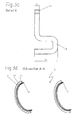
- the backing shell 9 is, as can also be seen from Figs. 3a, 3b, 3c and 3d, formed in the manner of a sheet metal disk. Teeth are provided along its outer circumference U A having a diameter d A . Three of these teeth are referenced in Fig. 3a with reference numbers Z1, Z2, Z3 by way of example.
- a profiling P In the area of the inner circumference U I of the backing shell 9 there is a profiling P, of which the design can be seen particularly in Figs. 3c and 3d.
- the profiling P exhibits, as shown in these figures, a circumscribing crease or crimp having a U-shaped cross section, which extends from the inner diameter d I to the diameter D I of the backing shell.
- the depth of the profiling P is designed in the embodiment according to Fig. 3c to be substantially larger than the sheet metal thickness y E of the backing shell 9, so that an effective operational thickness of the backing shell Y E results.
- Table 1 is based upon the presumption, that the identical inner and outer diameters of the individual disk 5.1, 5.2, 5.3, 6.1, 6.2, 6.3, 6.4 and disks 4, 8, 11 are employed as well as identical frictional forces are applied upon the multi-disk assembly L.
- Table 1 Comparison of characteristic sizes of a conventional backing plate 8 according to the state of the art (Fig. 5) to a backing plate 11 according to the invention (Fig.
- Fig.1b and 1c show multi-disk clutches 1 according to the invention consisting of similar components as shown in Fig. 1a but using friction plates having friction linings on one side only, so called single-side friction plates.
- the clutches 1 are comprised essentially of the elements of the multi-disk clutch 100 according to the state of the art.
- the multi-disk clutches 1 according to the invention are comprised, similarly to the above-described multi-disk clutch 100, of the four components - pressure plate 4, friction plates 16.1, 16.2, 16.3, 16.4, friction plates 15.1, 15.2, 15.3 as well as a backing plate 11, wherein the latter is designed in a particular fashion in accordance with the invention as shown in Fig. 4b and 4c.
- the arrangement of the multi-disk assembly L according to Fig. 1b shows the axial sequence of pressure plate 14, friction plate 16.1 with friction lining 16.1a, friction plate 15.1 with the friction lining 15.1a , friction plate 16.2 with friction lining 16.2a, friction plate 15.2 with the friction lining 15.2a , friction plate 16.3 with friction lining 16.3a, friction plate 15.3 with the friction linings 15.3a, and friction plate 16.4 with friction lining 16.4a.
- the inventive backing plate 11 comprised of backing shell 9 and core plate disk 10 with friction lining 10a (embodiment in the manner of a single-side-plate).
- the arrangement of the multi-disk assembly L according to Fig. 1c shows the axial sequence of pressure plate 14 with friction lining 14b, friction plate 16.1 with friction lining 16.1b, friction plate 15.1 with the friction lining 15.1b, friction plate 16.2 with friction lining 16.2b, friction plate 15.2 with the friction lining 15.2b , friction plate 16.3 with friction lining 16.3b, friction plate 15.3 with the friction linings 15.3b, and friction plate 16.4 with friction lining 16.4b.
- the inventive backing plate 11 comprised of backing shell 9 and core plate disk 10 without friction lining (embodiment in the manner of a steel plate).
Landscapes
- Engineering & Computer Science (AREA)
- General Engineering & Computer Science (AREA)
- Mechanical Engineering (AREA)
- Mechanical Operated Clutches (AREA)
Priority Applications (5)
| Application Number | Priority Date | Filing Date | Title |
|---|---|---|---|
| DE60222266T DE60222266T2 (de) | 2002-10-18 | 2002-10-18 | Abschlussscheibe für eine Lamellenanordnung |
| EP02023324A EP1411256B1 (fr) | 2002-10-18 | 2002-10-18 | Plateau d'appui dans un dispositif à disques |
| US10/685,619 US7063197B2 (en) | 2002-10-18 | 2003-10-14 | Backing plate for a disk assembly |
| JP2003354933A JP4504657B2 (ja) | 2002-10-18 | 2003-10-15 | ディスク組立体の受け板 |
| KR1020030072648A KR20040034527A (ko) | 2002-10-18 | 2003-10-17 | 디스크 조립체용 받침판 |
Applications Claiming Priority (1)
| Application Number | Priority Date | Filing Date | Title |
|---|---|---|---|
| EP02023324A EP1411256B1 (fr) | 2002-10-18 | 2002-10-18 | Plateau d'appui dans un dispositif à disques |
Publications (2)
| Publication Number | Publication Date |
|---|---|
| EP1411256A1 true EP1411256A1 (fr) | 2004-04-21 |
| EP1411256B1 EP1411256B1 (fr) | 2007-09-05 |
Family
ID=32039146
Family Applications (1)
| Application Number | Title | Priority Date | Filing Date |
|---|---|---|---|
| EP02023324A Expired - Lifetime EP1411256B1 (fr) | 2002-10-18 | 2002-10-18 | Plateau d'appui dans un dispositif à disques |
Country Status (5)
| Country | Link |
|---|---|
| US (1) | US7063197B2 (fr) |
| EP (1) | EP1411256B1 (fr) |
| JP (1) | JP4504657B2 (fr) |
| KR (1) | KR20040034527A (fr) |
| DE (1) | DE60222266T2 (fr) |
Cited By (3)
| Publication number | Priority date | Publication date | Assignee | Title |
|---|---|---|---|---|
| EP1577575A1 (fr) * | 2004-03-17 | 2005-09-21 | Borg Warner Inc. | Embrayage à disques |
| WO2006007074A2 (fr) | 2004-06-24 | 2006-01-19 | Raybestos Products Company | Conception de disques alternatifs destinee a des embrayages a disques multiples |
| CN108779809A (zh) * | 2016-03-16 | 2018-11-09 | 有能沛思株式会社 | 湿式多板离合器 |
Families Citing this family (23)
| Publication number | Priority date | Publication date | Assignee | Title |
|---|---|---|---|---|
| JP5025249B2 (ja) * | 2006-12-15 | 2012-09-12 | Nskワーナー株式会社 | 発進クラッチ |
| JP4344396B2 (ja) * | 2007-09-12 | 2009-10-14 | 株式会社エフ・シー・シー | 動力伝達装置 |
| US8858032B2 (en) * | 2008-10-24 | 2014-10-14 | Cree, Inc. | Lighting device, heat transfer structure and heat transfer element |
| US8397891B2 (en) | 2009-04-27 | 2013-03-19 | Schaeffler Technologies AG & Co. KG | Brazed support ring |
| DE102009058129A1 (de) | 2009-12-12 | 2011-06-16 | Borgwarner Inc., Auburn Hills | Endlamelle für ein Lamellenpaket, reibschlüssig arbeitende Einrichtung mit einer solchen Endlamelle und Verfahren zur Herstellung einer solchen Endlamelle |
| DE112011104521B4 (de) * | 2010-12-22 | 2021-01-14 | Schaeffler Technologies AG & Co. KG | Kolben mit bidirektionaler Klemmdichtung |
| US9447878B2 (en) * | 2013-05-24 | 2016-09-20 | Schaeffler Technologies AG & Co. KG | Piston seal assembly |
| US10125853B2 (en) * | 2015-02-17 | 2018-11-13 | Allison Transmission, Inc. | Torque converter lockup clutch structure |
| DE102015011206A1 (de) * | 2015-04-08 | 2016-10-13 | Borgwarner Inc. | Reibschlüssig arbeitende Einrichtung mit Endlamellenanordnung, Verfahren zur Herstellung einer Zwischenlamelle für eine solche Einrichtung |
| DE102015013474A1 (de) | 2015-10-17 | 2017-04-20 | Borgwarner Inc. | Reibschlüssig arbeitende Einrichtung und Verwendung einer Zwischenlamelle oder/und einer Betätigungslamelle in einer solchen reibschlüssig arbeitenden Einrichtung |
| USD861059S1 (en) | 2015-11-27 | 2019-09-24 | New Ideas Manufacturing, LLC | Camera lens filter with traction frame |
| US10393988B2 (en) | 2015-11-27 | 2019-08-27 | New Ideas Manufacturing, LLC | Camera lens filter with traction frame |
| KR101675881B1 (ko) | 2015-12-24 | 2016-11-14 | 주식회사 엠제이로드텍 | 철근콘크리트 구조물 열화부의 단면 보수 및 보강공법 |
| US10215237B2 (en) | 2016-07-29 | 2019-02-26 | GM Global Technology Operations LLC | Multiple-piece backing plate having parts made of different materials |
| US10132364B2 (en) | 2016-07-29 | 2018-11-20 | GM Global Technology Operations LLC | Backing plate providing axial stiffness |
| USD810174S1 (en) | 2016-09-15 | 2018-02-13 | Breakthrough Photography, LLC | Step-up ring |
| DE102017100120A1 (de) * | 2017-01-04 | 2018-07-05 | Hoerbiger Antriebstechnik Holding Gmbh | Lamellenpaket sowie Lamellenkupplung oder Lamellenbremse |
| USD888804S1 (en) | 2018-05-04 | 2020-06-30 | New Ideas Manufacturing LLC | Step-up ring |
| JP7293865B2 (ja) * | 2019-05-28 | 2023-06-20 | マツダ株式会社 | 摩擦締結装置 |
| JP7255357B2 (ja) | 2019-05-28 | 2023-04-11 | マツダ株式会社 | 摩擦締結装置 |
| JP7293866B2 (ja) | 2019-05-28 | 2023-06-20 | マツダ株式会社 | 摩擦締結装置 |
| DE102019116682A1 (de) * | 2019-06-19 | 2020-12-24 | Hoerbiger Antriebstechnik Holding Gmbh | Endlamelle einer Lamellenkupplung, Baugruppe sowie Verfahren zur Herstellung einer Baugruppe |
| US10895288B1 (en) * | 2019-08-12 | 2021-01-19 | BD Engine Brake Inc. | Clutch pack retaining system |
Citations (4)
| Publication number | Priority date | Publication date | Assignee | Title |
|---|---|---|---|---|
| GB902093A (en) * | 1957-12-10 | 1962-07-25 | Dunlop Rubber Co | Improvements in brakes, clutches and the like |
| US3941221A (en) * | 1974-10-31 | 1976-03-02 | United States Steel Corporation | Disc brake rotor assembly |
| US4020937A (en) * | 1975-12-10 | 1977-05-03 | Borg-Warner Corporation | Fabricated clutch pressure plate |
| FR2533005A1 (fr) * | 1982-09-13 | 1984-03-16 | Gen Motors Corp | Dispositif a friction a plusieurs plateaux |
Family Cites Families (7)
| Publication number | Priority date | Publication date | Assignee | Title |
|---|---|---|---|---|
| JPS5329864Y2 (fr) * | 1974-11-25 | 1978-07-26 | ||
| JPS59136033U (ja) * | 1983-03-01 | 1984-09-11 | アイシン精機株式会社 | クラツチカバ−装置 |
| US5234090A (en) * | 1992-09-21 | 1993-08-10 | General Motors Corporation | Clearance adjustment for a multi-plate fluid operated friction clutch |
| JP3111768B2 (ja) * | 1993-08-24 | 2000-11-27 | トヨタ自動車株式会社 | 自動変速機の摩擦係合装置 |
| JP3599123B2 (ja) * | 1994-06-22 | 2004-12-08 | 本田技研工業株式会社 | トランスミッション用油圧ブレーキ |
| JPH09287622A (ja) * | 1996-04-19 | 1997-11-04 | Fuji Heavy Ind Ltd | 多板摩擦係合装置 |
| JP3229853B2 (ja) * | 1998-03-10 | 2001-11-19 | アイシン・エィ・ダブリュ株式会社 | 自動変速機 |
-
2002
- 2002-10-18 EP EP02023324A patent/EP1411256B1/fr not_active Expired - Lifetime
- 2002-10-18 DE DE60222266T patent/DE60222266T2/de not_active Expired - Lifetime
-
2003
- 2003-10-14 US US10/685,619 patent/US7063197B2/en not_active Expired - Lifetime
- 2003-10-15 JP JP2003354933A patent/JP4504657B2/ja not_active Expired - Lifetime
- 2003-10-17 KR KR1020030072648A patent/KR20040034527A/ko not_active Ceased
Patent Citations (4)
| Publication number | Priority date | Publication date | Assignee | Title |
|---|---|---|---|---|
| GB902093A (en) * | 1957-12-10 | 1962-07-25 | Dunlop Rubber Co | Improvements in brakes, clutches and the like |
| US3941221A (en) * | 1974-10-31 | 1976-03-02 | United States Steel Corporation | Disc brake rotor assembly |
| US4020937A (en) * | 1975-12-10 | 1977-05-03 | Borg-Warner Corporation | Fabricated clutch pressure plate |
| FR2533005A1 (fr) * | 1982-09-13 | 1984-03-16 | Gen Motors Corp | Dispositif a friction a plusieurs plateaux |
Cited By (4)
| Publication number | Priority date | Publication date | Assignee | Title |
|---|---|---|---|---|
| EP1577575A1 (fr) * | 2004-03-17 | 2005-09-21 | Borg Warner Inc. | Embrayage à disques |
| WO2006007074A2 (fr) | 2004-06-24 | 2006-01-19 | Raybestos Products Company | Conception de disques alternatifs destinee a des embrayages a disques multiples |
| EP1769169A4 (fr) * | 2004-06-24 | 2009-05-06 | Raybestos Prod Co | Conception de disques alternatifs destinee a des embrayages a disques multiples |
| CN108779809A (zh) * | 2016-03-16 | 2018-11-09 | 有能沛思株式会社 | 湿式多板离合器 |
Also Published As
| Publication number | Publication date |
|---|---|
| JP2004138243A (ja) | 2004-05-13 |
| DE60222266T2 (de) | 2008-05-29 |
| EP1411256B1 (fr) | 2007-09-05 |
| US20050000776A1 (en) | 2005-01-06 |
| JP4504657B2 (ja) | 2010-07-14 |
| KR20040034527A (ko) | 2004-04-28 |
| US7063197B2 (en) | 2006-06-20 |
| DE60222266D1 (de) | 2007-10-18 |
Similar Documents
| Publication | Publication Date | Title |
|---|---|---|
| EP1411256B1 (fr) | Plateau d'appui dans un dispositif à disques | |
| US7073650B2 (en) | Friction plate groove pattern | |
| US9068605B2 (en) | Wear resistant clutch plate | |
| US7527135B2 (en) | Multiplate friction clutch | |
| US5454454A (en) | Polygonal friction disk and method | |
| JPH039119A (ja) | 多板クラッチ又はブレーキのクラッチプレート | |
| US7150347B2 (en) | Drum assembly for a coupling arrangement | |
| CN101014780A (zh) | 用于自动变速器的平面联接器总成 | |
| JPH0631226Y2 (ja) | クラッチディスク | |
| US5960923A (en) | Hydraulic clutch with wave spring | |
| US20100294063A1 (en) | Friction damped gears | |
| US20010002641A1 (en) | Friction engaging device | |
| US5660259A (en) | Groove structure of wet-type friction engaging element | |
| JPS5965620A (ja) | 多板摩擦装置 | |
| JP2001234946A (ja) | 摩擦係合装置用ウェーブディスク | |
| JPS6121425A (ja) | クラツチフエ−シング | |
| US20010045140A1 (en) | Transmission input shaft | |
| US20060042903A1 (en) | Clutch housing and method of manufacturing thereof | |
| JP3894321B2 (ja) | バルブプレート | |
| JP3696664B2 (ja) | 多板クラッチ構造 | |
| US6752252B2 (en) | Multiplate clutch | |
| US7481306B2 (en) | Wet-type multiplate clutch | |
| US10132364B2 (en) | Backing plate providing axial stiffness | |
| JP7165581B2 (ja) | 車両の変速機用摩擦型シフト要素のための摩擦要素 | |
| US20070261932A1 (en) | Friction clutch with multiple belleville springs |
Legal Events
| Date | Code | Title | Description |
|---|---|---|---|
| PUAI | Public reference made under article 153(3) epc to a published international application that has entered the european phase |
Free format text: ORIGINAL CODE: 0009012 |
|
| AK | Designated contracting states |
Kind code of ref document: A1 Designated state(s): AT BE BG CH CY CZ DE DK EE ES FI FR GB GR IE IT LI LU MC NL PT SE SK TR |
|
| AX | Request for extension of the european patent |
Extension state: AL LT LV MK RO SI |
|
| 17P | Request for examination filed |
Effective date: 20040408 |
|
| AKX | Designation fees paid |
Designated state(s): DE FR GB IT |
|
| RAP1 | Party data changed (applicant data changed or rights of an application transferred) |
Owner name: BORGWARNER INC. |
|
| GRAP | Despatch of communication of intention to grant a patent |
Free format text: ORIGINAL CODE: EPIDOSNIGR1 |
|
| GRAS | Grant fee paid |
Free format text: ORIGINAL CODE: EPIDOSNIGR3 |
|
| GRAA | (expected) grant |
Free format text: ORIGINAL CODE: 0009210 |
|
| AK | Designated contracting states |
Kind code of ref document: B1 Designated state(s): DE FR GB IT |
|
| REG | Reference to a national code |
Ref country code: GB Ref legal event code: FG4D |
|
| REF | Corresponds to: |
Ref document number: 60222266 Country of ref document: DE Date of ref document: 20071018 Kind code of ref document: P |
|
| ET | Fr: translation filed | ||
| PLBE | No opposition filed within time limit |
Free format text: ORIGINAL CODE: 0009261 |
|
| STAA | Information on the status of an ep patent application or granted ep patent |
Free format text: STATUS: NO OPPOSITION FILED WITHIN TIME LIMIT |
|
| 26N | No opposition filed |
Effective date: 20080606 |
|
| PGFP | Annual fee paid to national office [announced via postgrant information from national office to epo] |
Ref country code: GB Payment date: 20080915 Year of fee payment: 7 |
|
| PGFP | Annual fee paid to national office [announced via postgrant information from national office to epo] |
Ref country code: IT Payment date: 20081015 Year of fee payment: 7 |
|
| PG25 | Lapsed in a contracting state [announced via postgrant information from national office to epo] |
Ref country code: GB Free format text: LAPSE BECAUSE OF NON-PAYMENT OF DUE FEES Effective date: 20091018 |
|
| PG25 | Lapsed in a contracting state [announced via postgrant information from national office to epo] |
Ref country code: IT Free format text: LAPSE BECAUSE OF NON-PAYMENT OF DUE FEES Effective date: 20091018 |
|
| REG | Reference to a national code |
Ref country code: FR Ref legal event code: PLFP Year of fee payment: 15 |
|
| REG | Reference to a national code |
Ref country code: FR Ref legal event code: PLFP Year of fee payment: 16 |
|
| REG | Reference to a national code |
Ref country code: FR Ref legal event code: PLFP Year of fee payment: 17 |
|
| PGFP | Annual fee paid to national office [announced via postgrant information from national office to epo] |
Ref country code: FR Payment date: 20180920 Year of fee payment: 17 |
|
| PG25 | Lapsed in a contracting state [announced via postgrant information from national office to epo] |
Ref country code: FR Free format text: LAPSE BECAUSE OF NON-PAYMENT OF DUE FEES Effective date: 20191031 |
|
| PGFP | Annual fee paid to national office [announced via postgrant information from national office to epo] |
Ref country code: DE Payment date: 20210916 Year of fee payment: 20 |
|
| REG | Reference to a national code |
Ref country code: DE Ref legal event code: R071 Ref document number: 60222266 Country of ref document: DE |