EP1411265A2 - Support de couple, en particulier pour le support d'un moteur contre la carosserie d'un véhicule - Google Patents
Support de couple, en particulier pour le support d'un moteur contre la carosserie d'un véhicule Download PDFInfo
- Publication number
- EP1411265A2 EP1411265A2 EP03023194A EP03023194A EP1411265A2 EP 1411265 A2 EP1411265 A2 EP 1411265A2 EP 03023194 A EP03023194 A EP 03023194A EP 03023194 A EP03023194 A EP 03023194A EP 1411265 A2 EP1411265 A2 EP 1411265A2
- Authority
- EP
- European Patent Office
- Prior art keywords
- socket housing
- inner sleeve
- damping body
- support according
- torque support
- Prior art date
- Legal status (The legal status is an assumption and is not a legal conclusion. Google has not performed a legal analysis and makes no representation as to the accuracy of the status listed.)
- Withdrawn
Links
Images


Classifications
-
- F—MECHANICAL ENGINEERING; LIGHTING; HEATING; WEAPONS; BLASTING
- F16—ENGINEERING ELEMENTS AND UNITS; GENERAL MEASURES FOR PRODUCING AND MAINTAINING EFFECTIVE FUNCTIONING OF MACHINES OR INSTALLATIONS; THERMAL INSULATION IN GENERAL
- F16F—SPRINGS; SHOCK-ABSORBERS; MEANS FOR DAMPING VIBRATION
- F16F1/00—Springs
- F16F1/36—Springs made of rubber or other material having high internal friction, e.g. thermoplastic elastomers
- F16F1/38—Springs made of rubber or other material having high internal friction, e.g. thermoplastic elastomers with a sleeve of elastic material between a rigid outer sleeve and a rigid inner sleeve or pin, i.e. bushing-type
- F16F1/387—Springs made of rubber or other material having high internal friction, e.g. thermoplastic elastomers with a sleeve of elastic material between a rigid outer sleeve and a rigid inner sleeve or pin, i.e. bushing-type comprising means for modifying the rigidity in particular directions
-
- F—MECHANICAL ENGINEERING; LIGHTING; HEATING; WEAPONS; BLASTING
- F16—ENGINEERING ELEMENTS AND UNITS; GENERAL MEASURES FOR PRODUCING AND MAINTAINING EFFECTIVE FUNCTIONING OF MACHINES OR INSTALLATIONS; THERMAL INSULATION IN GENERAL
- F16F—SPRINGS; SHOCK-ABSORBERS; MEANS FOR DAMPING VIBRATION
- F16F1/00—Springs
- F16F1/36—Springs made of rubber or other material having high internal friction, e.g. thermoplastic elastomers
- F16F1/38—Springs made of rubber or other material having high internal friction, e.g. thermoplastic elastomers with a sleeve of elastic material between a rigid outer sleeve and a rigid inner sleeve or pin, i.e. bushing-type
- F16F1/3842—Method of assembly, production or treatment; Mounting thereof
- F16F1/3849—Mounting brackets therefor, e.g. stamped steel brackets; Restraining links
Definitions
- the invention relates to a torque arm, in particular for support of the engine on the body of a motor vehicle.
- the torque arm is with a first socket housing in which a first inner sleeve is arranged, a second socket housing in which a second Inner sleeve is arranged, one of the first socket housing and the second Socket housing connecting support arm and a rubber elastic Provide damping body.
- the damping body is in the first Socket housing and the second socket housing vulcanized. moreover the damping body supports the first inner sleeve and the second inner sleeve from.
- EP 0 849 491 A2 discloses a torque arm, which is a support arm has at its opposite ends with a Inner sleeve damping receiving socket housing is provided.
- the Support arm and the socket housing form a support cage that is integral with a damping body made of an elastomeric material connected is.
- the one that supports the inner sleeves in the socket housings Damping body is vulcanized directly into the socket housing, whereby the inner sleeves during the vulcanization of the damping body be cohesively connected to this.
- Torque support is also known from DE 196 31 893 A1.
- the invention has for its object a torque arm of the beginning mentioned type to further develop that simple achieve a relatively long service life and cost-effective production leaves.
- the damping body at least in the region of the first Socket housing has an inner opening into which the first inner sleeve is pressed in with a radial preload.
- the torque arm according to the invention is based on the knowledge that Press the inner sleeve non-positively into an inner opening of the socket housing. This results in a radial prestressing of the inner sleeve, which contributes to a relatively long lifespan.
- the inside opening and the inner sleeve are an interference fit that is reliable Ensures interference fit of the inner sleeve in the damping body.
- one integral connection of the inner sleeve and damping body, as in The state of the art is no longer necessary. Pressing the Inner sleeve in the damping body can be easily realized so that cost-effective production is guaranteed.
- the damping body advantageously consists of a rubber-elastic Material, preferably natural rubber or ethylene-propylene-diene rubber (EPDM).
- a rubber-elastic Material preferably natural rubber or ethylene-propylene-diene rubber (EPDM).
- first socket housing, the second socket housing and the support arm a support cage for the vulcanized Form damping body.
- the damping body can be used directly vulcanized into the socket housing, which is a reliable cohesive connection results.
- the support cage is designed as a one-piece casting, the Made of metal, preferably aluminum, or plastic to make it simple Way to enable complex shaping.
- the design of the torque arm according to the invention is the support cage preferably by forming, preferably deep drawing, from sheet metal or plastic plates manufactured. Such manufacture is comparatively inexpensive and ensures a lightweight construction.
- the damping body preferably forms a coating on the support cage out.
- the one that arises during the vulcanization of the damping body Plating provides a protective layer for the sake of high strength expediently made of metal support cage, which the Corrosion resistance of the torque arm increased.
- the second inner sleeve is integral with the damping body connected.
- the bond between the second inner sleeve and the Damping body can in a known manner in the vulcanization of Damping body are generated.
- the second inner sleeve with a large number of recesses to provide.
- the recesses contribute to the weight the, for example, approximately trapezoidal second inner sleeve to reduce.
- the central axis running through the first inner sleeve can be parallel or angular, preferably orthogonal, to a through the second inner sleeve Center axis.
- the orientation of the central axes depends regularly depend on the installation position of the torque arm.
- the damping body is preferably in the region of the second socket housing provided with recesses, preferably at least one the recesses partially bordered the second inner sleeve.
- the second socket housing and / or the support arm with one bulge bulging outwards are the second socket housing and / or the support arm with one bulge bulging outwards.
- the bead increases the rigidity of the Torque arm, especially when it is formed is manufactured.
- the second socket housing is a substantially circular cylindrical Has lateral surface, which in the region of the bead with at least an indentation is provided. Through the indentation, on the one hand increase the strength of the second socket housing. On the other hand the indentation for an additional form fit between the second Socket housing and the damping body with the result that the Damping body reliably connected to the second socket housing becomes.
- the damping ability can be through the indentation of the damping body.
- the support arm Especially when the torque arm is made by forming, it has also proven to be particularly advantageous to use the support arm to provide at least one reinforcing plate which is in a to the through the second inner sleeve running central axis vertical plane extends.
- the reinforcement plate increases the rigidity of the Torque support in the direction of its longitudinal axis, among other things.
- the reinforcing plate preferably goes into a radially projecting edge section of the second socket housing to ensure an even To ensure power flow.
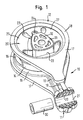
- the torque arm shown in Fig. 1 is used to support the motor on the body of a motor vehicle.
- the torque arm points to this Purpose of a first socket housing 11 and a second socket housing 12, which are connected by a support arm 13.
- the socket housing 11, the socket housing 12 and the support arm 13 form one Support cage 10 for an existing of a rubber-elastic material Damping body 20.
- the support cage 10 is made of a deformed and in places welded sheet.
- the damping body is 20 integrally connected to the support cage 10.
- the support cage 10 during the vulcanization of the damping body 20 of this enclosed.
- the damping body 20 is provided in the region of the socket housing 11 with an inner opening 21 into which a first inner sleeve 30 is pressed with a radial prestress.
- the inner sleeve 30 is thus non-positively connected to the damping body 20.
- a second inner sleeve 31 arranged in the socket housing 12 is integrally connected to the damping body 20.
- the approximately trapezoidal inner sleeve 31, which is provided with a plurality of recesses 32 to reduce its weight, is connected to the damping body 20 during the manufacture of the torque arm by the vulcanization of the latter.
- the damping body 20 also has recesses 22, 23, 24 in the region of the second socket housing 12, which have a targeted influence on the deformability of the damping body 20 and thus on the damping behavior of the torque arm.
- Fig. 3 also shows that a extending through the inner sleeve 30 Central axis y orthogonal to a central axis running through the inner sleeve 31 z is oriented.
- the support arm 13 is congruent with two arranged reinforcing plates 17 which are in a to extend the central axis z vertical plane.
- the reinforcement plates 17 serve the rigidity of those manufactured primarily by forming To increase the torque arm in the direction of the longitudinal axis x. Which differ from go the socket housing 11 flared reinforcing plates 17 into an edge section 18 surrounding the socket housing 12, which compared to a substantially circular cylindrical surface 15 of the Socket housing 12 protrudes in the radial direction.
- the support arm 13 In the area of the first Socket housing 11 facing end of the reinforcing plate 17 the support arm 13 provided with a recess 19, as in particular in the 1 and 5 can be seen.
- the one notch of the reinforcement plate 17 facing end face of the support arm 13 constituting recess 19 serves to remove voltage peaks in the area of the transition from the socket housing 11 to avoid the support arm 13.
- the socket housing 12 and the support arm 13 with one after provided bulge 14 on the outside, as can be seen in particular in FIG. 2 is.
- the bead 14 stiffens the support cage 10 and thus the torque arm.
- the lateral surface 15 of the socket housing 12 is in the region of the bead 14 provided with two opposite indentations 16.
- the dents 16 contribute to an additional positive fit between the Damping body 20 and the socket housing 12. Second, influence which are arranged in the region of the legs 27 of the damping body 20 Indentations 16 the damping capacity of the thighs 27 formed and supporting the inner sleeve 31 supporting spring.
- the support cage 10 is without the damping body 20 and without the inner sleeves 30, 31 shown. 11 leaves the edge section 18th and recognize the indentation 16 of the lateral surface 15 particularly well. Moreover it can be clearly seen from FIGS. 12 to 14 that the support cage 10 is made by forming.
- the one consisting of two adjoining Support arm 13, which is composed of sheet metal sections, is shaped such that a Passage 26 is formed, as can be seen in particular from FIG. 14.
- The, 3 the damping body 20 receiving Passage 26 ensures a continuous connection of the damping body 20 from the area of the socket housing 11 in the area of the socket housing 12 and thus contributes to a reliable attachment of the damping body 20 on the support cage 10.
- the torque arm described above is characterized by a simple and inexpensive manufacturing.
- the main reason for this is that the Support cage 10 with the damping body 20 during its vulcanization is cohesively connected.
- the one by reshaping an appropriately tailored one Sheet-metal support cage 10 also contributes to a Vehicle construction necessary lightweight construction.
- the torque arm has a relatively long service life. This is mainly due to the fact that the inner sleeve 30 with radial bias is applied. The radial preload will thereby achieved that the inner sleeve 30 into the inner opening 21 of the damping body 20 is pressed. In contrast to this, the inner sleeve 31 in the area of the socket housing 12 integrally with the damping body 20 connected.
- the inner sleeve 31st is partially surrounded by the recesses 22, 23 around the legs 27 and thus the inner sleeve 31 in the socket housing 12 supporting To form suspension spring.
- the non-positive connection of the inner sleeve 30 with the damping body 20 not least contributes to a recycling-friendly Design of the torque arm, since the inner sleeve 30 and Damping body 20 can be separated relatively easily.
Landscapes
- Engineering & Computer Science (AREA)
- General Engineering & Computer Science (AREA)
- Mechanical Engineering (AREA)
- Manufacturing & Machinery (AREA)
- Springs (AREA)
- Vibration Prevention Devices (AREA)
Applications Claiming Priority (2)
| Application Number | Priority Date | Filing Date | Title |
|---|---|---|---|
| DE2002147757 DE10247757B3 (de) | 2002-10-14 | 2002-10-14 | Drehmomentstütze, insbesondere zum Abstützen des Motors an der Karosserie eines Kraftfahrzeugs |
| DE10247757 | 2002-10-14 |
Publications (2)
| Publication Number | Publication Date |
|---|---|
| EP1411265A2 true EP1411265A2 (fr) | 2004-04-21 |
| EP1411265A3 EP1411265A3 (fr) | 2004-06-16 |
Family
ID=30775604
Family Applications (1)
| Application Number | Title | Priority Date | Filing Date |
|---|---|---|---|
| EP03023194A Withdrawn EP1411265A3 (fr) | 2002-10-14 | 2003-10-13 | Support de couple, en particulier pour le support d'un moteur contre la carosserie d'un véhicule |
Country Status (2)
| Country | Link |
|---|---|
| EP (1) | EP1411265A3 (fr) |
| DE (1) | DE10247757B3 (fr) |
Cited By (2)
| Publication number | Priority date | Publication date | Assignee | Title |
|---|---|---|---|---|
| JP2012197821A (ja) * | 2011-03-18 | 2012-10-18 | Toyo Tire & Rubber Co Ltd | 防振装置 |
| JP2015036579A (ja) * | 2013-08-14 | 2015-02-23 | 山下ゴム株式会社 | 樹脂トルクロッド |
Families Citing this family (5)
| Publication number | Priority date | Publication date | Assignee | Title |
|---|---|---|---|---|
| DE102008021916C5 (de) * | 2008-05-02 | 2019-04-18 | WEGU GmbH Schwingungsdämpfung | Seitenstabiles Pendellager |
| DE102012009458B4 (de) * | 2012-05-11 | 2014-09-11 | Anvis Deutschland Gmbh | Lager zum elastischen Koppeln zweier Bauteile |
| DE102013213442A1 (de) * | 2013-07-09 | 2015-01-15 | Zf Friedrichshafen Ag | Drehmomentstütze für ein Schienenfahrzeug |
| DE102015108836A1 (de) * | 2015-06-03 | 2016-12-08 | Weberit Werke Dräbing Gmbh | Torsionsdämpfer |
| DE102022102369A1 (de) | 2022-02-01 | 2023-08-03 | Süddeutsche Gelenkscheibenfabrik Gesellschaft mit beschränkter Haftung & Co. KG. | Elastisches Lager |
Citations (2)
| Publication number | Priority date | Publication date | Assignee | Title |
|---|---|---|---|---|
| DE19631893A1 (de) | 1996-08-07 | 1998-02-12 | Metzeler Gimetall Ag | Pendelstütze und Verfahren zu deren Herstellung |
| EP0849491A2 (fr) | 1996-11-29 | 1998-06-24 | BTR AVS Technical Centre GmbH | Support pendulaire |
Family Cites Families (1)
| Publication number | Priority date | Publication date | Assignee | Title |
|---|---|---|---|---|
| JPS4820357B1 (fr) * | 1968-05-27 | 1973-06-20 |
-
2002
- 2002-10-14 DE DE2002147757 patent/DE10247757B3/de not_active Expired - Fee Related
-
2003
- 2003-10-13 EP EP03023194A patent/EP1411265A3/fr not_active Withdrawn
Patent Citations (2)
| Publication number | Priority date | Publication date | Assignee | Title |
|---|---|---|---|---|
| DE19631893A1 (de) | 1996-08-07 | 1998-02-12 | Metzeler Gimetall Ag | Pendelstütze und Verfahren zu deren Herstellung |
| EP0849491A2 (fr) | 1996-11-29 | 1998-06-24 | BTR AVS Technical Centre GmbH | Support pendulaire |
Cited By (3)
| Publication number | Priority date | Publication date | Assignee | Title |
|---|---|---|---|---|
| JP2012197821A (ja) * | 2011-03-18 | 2012-10-18 | Toyo Tire & Rubber Co Ltd | 防振装置 |
| JP2015036579A (ja) * | 2013-08-14 | 2015-02-23 | 山下ゴム株式会社 | 樹脂トルクロッド |
| CN105378331A (zh) * | 2013-08-14 | 2016-03-02 | 山下橡胶株式会社 | 树脂扭力杆 |
Also Published As
| Publication number | Publication date |
|---|---|
| EP1411265A3 (fr) | 2004-06-16 |
| DE10247757B3 (de) | 2004-02-26 |
Similar Documents
| Publication | Publication Date | Title |
|---|---|---|
| DE69602789T2 (de) | Aufhängungssystem | |
| EP2478254B1 (fr) | Manchon élastique, en particulier manchon de bras oscillant combiné | |
| DE69110822T2 (de) | Stossdämpfendes Lager. | |
| DE2726676C2 (de) | Federelement zur elastischen Lagerung von Antriebs- oder sonstigen Aggregaten | |
| DE10106915C2 (de) | Federungsanordnung | |
| EP0623483B1 (fr) | Palier en matière plastique pour barres stabilisatrices dans véhicules automobiles | |
| DE102005043234B4 (de) | Verfahren zur Herstellung eines elastomeren Buchsenlagers | |
| DE102013218055A1 (de) | Lagervorrichtung einer Querblattfeder, die im Bereich einer Fahrzeugachse eines Fahrzeuges montierbar ist | |
| DE102009040163B4 (de) | Achsführungslager zur Ankopplung einer Hinterachse an einen Fahrzeugaufbau | |
| DE102011007390A1 (de) | Fahrwerkbauteil | |
| DE102009051159A1 (de) | Lageranordnung mit einer Lagerbuchse | |
| DE10247757B3 (de) | Drehmomentstütze, insbesondere zum Abstützen des Motors an der Karosserie eines Kraftfahrzeugs | |
| DE102005003945B4 (de) | Buchsenlager mit in Umfangsrichtung wechselnder radialer Steifigkeit | |
| DE19923698A1 (de) | Querlenker | |
| EP1505311A1 (fr) | Coussinet | |
| EP1878937A1 (fr) | Support de train d'atterrissage élastique | |
| DE60007802T2 (de) | Lagerbuchse | |
| DE102007037704A1 (de) | Lageranordnung mit einer Lagerbuchse und Verfahren zur Herstellung einer Lagerbuchse einer Lageranordnung | |
| EP1691104A1 (fr) | Support élastique | |
| DE102022203398B4 (de) | Befestigungsanordnung zur Befestigung eines Schwingungsdämpfers an einem Radträger eines Kraftfahrzeugs. | |
| DE10011845A1 (de) | Lenker in Schalenbauweise | |
| DE102005036931B4 (de) | Lenker für Radaufhängungen | |
| DE102021108720B4 (de) | Selbsthemmendes Buchsenlager | |
| DE19735753A1 (de) | Drehstabanordnung | |
| EP3781418B1 (fr) | Support de roue pour un véhicule à moteur |
Legal Events
| Date | Code | Title | Description |
|---|---|---|---|
| PUAI | Public reference made under article 153(3) epc to a published international application that has entered the european phase |
Free format text: ORIGINAL CODE: 0009012 |
|
| AK | Designated contracting states |
Kind code of ref document: A2 Designated state(s): AT BE BG CH CY CZ DE DK EE ES FI FR GB GR HU IE IT LI LU MC NL PT RO SE SI SK TR |
|
| AX | Request for extension of the european patent |
Extension state: AL LT LV MK |
|
| PUAL | Search report despatched |
Free format text: ORIGINAL CODE: 0009013 |
|
| AK | Designated contracting states |
Kind code of ref document: A3 Designated state(s): AT BE BG CH CY CZ DE DK EE ES FI FR GB GR HU IE IT LI LU MC NL PT RO SE SI SK TR |
|
| AX | Request for extension of the european patent |
Extension state: AL LT LV MK |
|
| AKX | Designation fees paid | ||
| REG | Reference to a national code |
Ref country code: DE Ref legal event code: 8566 |
|
| STAA | Information on the status of an ep patent application or granted ep patent |
Free format text: STATUS: THE APPLICATION IS DEEMED TO BE WITHDRAWN |
|
| 18D | Application deemed to be withdrawn |
Effective date: 20041217 |