EP1411271B1 - Kettenspanner - Google Patents
Kettenspanner Download PDFInfo
- Publication number
- EP1411271B1 EP1411271B1 EP03256509A EP03256509A EP1411271B1 EP 1411271 B1 EP1411271 B1 EP 1411271B1 EP 03256509 A EP03256509 A EP 03256509A EP 03256509 A EP03256509 A EP 03256509A EP 1411271 B1 EP1411271 B1 EP 1411271B1
- Authority
- EP
- European Patent Office
- Prior art keywords
- register ring
- plunger
- ring
- housing
- register
- Prior art date
- Legal status (The legal status is an assumption and is not a legal conclusion. Google has not performed a legal analysis and makes no representation as to the accuracy of the status listed.)
- Expired - Lifetime
Links
- 239000000463 material Substances 0.000 claims description 23
- 238000005452 bending Methods 0.000 claims description 17
- 229910000831 Steel Inorganic materials 0.000 claims description 9
- 239000010959 steel Substances 0.000 claims description 9
- 238000012360 testing method Methods 0.000 description 6
- 230000001105 regulatory effect Effects 0.000 description 5
- 238000013461 design Methods 0.000 description 4
- 229910001220 stainless steel Inorganic materials 0.000 description 4
- 238000000034 method Methods 0.000 description 3
- 238000012545 processing Methods 0.000 description 3
- 229910000975 Carbon steel Inorganic materials 0.000 description 2
- 230000002159 abnormal effect Effects 0.000 description 2
- 230000003139 buffering effect Effects 0.000 description 2
- 239000010962 carbon steel Substances 0.000 description 2
- DYRBFMPPJATHRF-UHFFFAOYSA-N chromium silicon Chemical compound [Si].[Cr] DYRBFMPPJATHRF-UHFFFAOYSA-N 0.000 description 2
- 238000010276 construction Methods 0.000 description 2
- 238000005242 forging Methods 0.000 description 2
- 238000012423 maintenance Methods 0.000 description 2
- 238000005259 measurement Methods 0.000 description 2
- 230000003746 surface roughness Effects 0.000 description 2
- 229910000838 Al alloy Inorganic materials 0.000 description 1
- 229910000851 Alloy steel Inorganic materials 0.000 description 1
- OKTJSMMVPCPJKN-UHFFFAOYSA-N Carbon Chemical compound [C] OKTJSMMVPCPJKN-UHFFFAOYSA-N 0.000 description 1
- 229910001018 Cast iron Inorganic materials 0.000 description 1
- 229910000617 Mangalloy Inorganic materials 0.000 description 1
- 229910000639 Spring steel Inorganic materials 0.000 description 1
- 230000002411 adverse Effects 0.000 description 1
- 230000005540 biological transmission Effects 0.000 description 1
- 229910052799 carbon Inorganic materials 0.000 description 1
- 238000005255 carburizing Methods 0.000 description 1
- VNTLIPZTSJSULJ-UHFFFAOYSA-N chromium molybdenum Chemical compound [Cr].[Mo] VNTLIPZTSJSULJ-UHFFFAOYSA-N 0.000 description 1
- 238000010622 cold drawing Methods 0.000 description 1
- 230000007797 corrosion Effects 0.000 description 1
- 238000005260 corrosion Methods 0.000 description 1
- 238000010586 diagram Methods 0.000 description 1
- 238000011156 evaluation Methods 0.000 description 1
- 239000012530 fluid Substances 0.000 description 1
- 238000000227 grinding Methods 0.000 description 1
- 229910001234 light alloy Inorganic materials 0.000 description 1
- 230000001050 lubricating effect Effects 0.000 description 1
- 238000005461 lubrication Methods 0.000 description 1
- 238000004519 manufacturing process Methods 0.000 description 1
- 238000003672 processing method Methods 0.000 description 1
- 230000002035 prolonged effect Effects 0.000 description 1
- 238000010791 quenching Methods 0.000 description 1
- 230000000171 quenching effect Effects 0.000 description 1
- 230000000452 restraining effect Effects 0.000 description 1
- 238000005096 rolling process Methods 0.000 description 1
- 230000035939 shock Effects 0.000 description 1
- 238000005482 strain hardening Methods 0.000 description 1
- 238000007669 thermal treatment Methods 0.000 description 1
Images




Classifications
-
- F—MECHANICAL ENGINEERING; LIGHTING; HEATING; WEAPONS; BLASTING
- F16—ENGINEERING ELEMENTS AND UNITS; GENERAL MEASURES FOR PRODUCING AND MAINTAINING EFFECTIVE FUNCTIONING OF MACHINES OR INSTALLATIONS; THERMAL INSULATION IN GENERAL
- F16H—GEARING
- F16H7/00—Gearings for conveying rotary motion by endless flexible members
- F16H7/08—Means for varying tension of belts, ropes or chains
- F16H7/0829—Means for varying tension of belts, ropes or chains with vibration damping means
- F16H7/0836—Means for varying tension of belts, ropes or chains with vibration damping means of the fluid and restriction type, e.g. dashpot
-
- F—MECHANICAL ENGINEERING; LIGHTING; HEATING; WEAPONS; BLASTING
- F16—ENGINEERING ELEMENTS AND UNITS; GENERAL MEASURES FOR PRODUCING AND MAINTAINING EFFECTIVE FUNCTIONING OF MACHINES OR INSTALLATIONS; THERMAL INSULATION IN GENERAL
- F16H—GEARING
- F16H7/00—Gearings for conveying rotary motion by endless flexible members
- F16H7/08—Means for varying tension of belts, ropes or chains
- F16H2007/0802—Actuators for final output members
- F16H2007/0806—Compression coil springs
-
- F—MECHANICAL ENGINEERING; LIGHTING; HEATING; WEAPONS; BLASTING
- F16—ENGINEERING ELEMENTS AND UNITS; GENERAL MEASURES FOR PRODUCING AND MAINTAINING EFFECTIVE FUNCTIONING OF MACHINES OR INSTALLATIONS; THERMAL INSULATION IN GENERAL
- F16H—GEARING
- F16H7/00—Gearings for conveying rotary motion by endless flexible members
- F16H7/08—Means for varying tension of belts, ropes or chains
- F16H2007/0802—Actuators for final output members
- F16H2007/0812—Fluid pressure
-
- F—MECHANICAL ENGINEERING; LIGHTING; HEATING; WEAPONS; BLASTING
- F16—ENGINEERING ELEMENTS AND UNITS; GENERAL MEASURES FOR PRODUCING AND MAINTAINING EFFECTIVE FUNCTIONING OF MACHINES OR INSTALLATIONS; THERMAL INSULATION IN GENERAL
- F16H—GEARING
- F16H7/00—Gearings for conveying rotary motion by endless flexible members
- F16H7/08—Means for varying tension of belts, ropes or chains
- F16H7/0848—Means for varying tension of belts, ropes or chains with means for impeding reverse motion
- F16H2007/0853—Ratchets
-
- F—MECHANICAL ENGINEERING; LIGHTING; HEATING; WEAPONS; BLASTING
- F16—ENGINEERING ELEMENTS AND UNITS; GENERAL MEASURES FOR PRODUCING AND MAINTAINING EFFECTIVE FUNCTIONING OF MACHINES OR INSTALLATIONS; THERMAL INSULATION IN GENERAL
- F16H—GEARING
- F16H7/00—Gearings for conveying rotary motion by endless flexible members
- F16H7/08—Means for varying tension of belts, ropes or chains
- F16H7/0848—Means for varying tension of belts, ropes or chains with means for impeding reverse motion
- F16H2007/0853—Ratchets
- F16H2007/0855—Ratchets comprising a clip member engaging with the rack teeth
-
- F—MECHANICAL ENGINEERING; LIGHTING; HEATING; WEAPONS; BLASTING
- F16—ENGINEERING ELEMENTS AND UNITS; GENERAL MEASURES FOR PRODUCING AND MAINTAINING EFFECTIVE FUNCTIONING OF MACHINES OR INSTALLATIONS; THERMAL INSULATION IN GENERAL
- F16H—GEARING
- F16H7/00—Gearings for conveying rotary motion by endless flexible members
- F16H7/08—Means for varying tension of belts, ropes or chains
- F16H7/0848—Means for varying tension of belts, ropes or chains with means for impeding reverse motion
- F16H2007/0859—Check valves
-
- F—MECHANICAL ENGINEERING; LIGHTING; HEATING; WEAPONS; BLASTING
- F16—ENGINEERING ELEMENTS AND UNITS; GENERAL MEASURES FOR PRODUCING AND MAINTAINING EFFECTIVE FUNCTIONING OF MACHINES OR INSTALLATIONS; THERMAL INSULATION IN GENERAL
- F16H—GEARING
- F16H7/00—Gearings for conveying rotary motion by endless flexible members
- F16H7/08—Means for varying tension of belts, ropes or chains
- F16H2007/0876—Control or adjustment of actuators
- F16H2007/0878—Disabling during transport
Definitions
- the present invention relates to a chain tensioner for keeping the tension of a chain constant, which is placed on a loose side of the chain, in a chain transmission system for transmitting the rotation of a crank shaft to a cam shaft, for example, in a vehicle engine.
- a chain tensioner having the following structure is conventionally known.
- a spring and a plunger are housed within a housing so that outward projection ability is imparted to the plunger by an elastic force of the spring.
- the plunger which is elastically pressed by the spring, pushes the chain so as to bring the chain into a tensed state.
- the pushing force imparted to the plunger by the chain is buffered by an oil pressure in an oil hydraulic damper chamber formed in the rear of the plunger to keep a tensile force of the chain constant.
- specific structures for example, those described in, for example, Japanese Patent Laid-Open Publication Nos. 2001-146946 and 2001-355691 , which constitutes the closest prior art, are known.
- a register ring is provided as a member for regulating the backward movement of the plunger (return regulation).
- the register ring is engaged with a first stopper formed on the inner circumferential surface of the housing while being fitted into any of a plurality of engagement grooves formed on the outer circumferential surface of the plunger.
- the register ring plays an important role in regulation of the backward movement of the plunger so as to prevent the chain from being excessively loosened and the like.
- the register ring is an important component in view of realization of the functions of the chain tensioner. Therefore, the design conditions of the register ring such as a shape and a material should be deliberately determined in consideration of the functions of the chain tensioner.
- the present invention has an object of optimizing the design conditions of a register ring in compliance with the required functions so as to improve the durability, the operational stability, and the like of a chain tensioner.
- a chain tensioner is disclosed with include: a cylindrical housing with a closed end; a plunger slidably fitted into the housing on its inner circumference; a return spring for imparting outward projection ability to the plunger; a plurality of engagement grooves formed on an outer circumference of the plunger; a first stopper formed on the inner circumference of the housing; and a register ring capable of elastically increasing and reducing its diameter, being engaged with the engagement grooves, any of the engagement grooves being engaged with the first stopper through the register ring to regulate backward movement of the plunger, wherein the register ring is formed of a steel material having a tensile strength of 1000 to 3500 N/mm 2 , an overlapping allowance of the register ring with respect to the engagement grooves of the plunger is set within the range of 30 to 50% of a wire diameter of the register ring.
- the maximum bending stress of the register ring having an increased diameter, when it is positioned between the engagement grooves, is set within the range of 500 to 1700 N/mm 2 .
- the register ring is formed of a steel wire having a tensile strength of 1000 to 3500 N/mm 2 as described above, the durability of the register ring can be enhanced.
- the plunger can be made to follow the movement of a chain so as to smoothly project even during engine operation.
- the register ring is formed of an oil-tempered wire, the heat resistance of the register ring can be ensured.
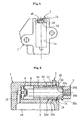
- a chain tensioner As shown in Figs. 1 (a), 1(b) and 2 , a chain tensioner according to the present invention is assembled with the following components serving as main components.
- the chain tensioner includes: a housing 1; a plunger 3, a return spring 5 and a check valve 6 accommodated in the housing 1 on its inner circumference; and a register ring 7 fitted to the plunger 3 on its outer circumference.
- a direction in which the plunger 3 projects with respect to the housing 1 is denoted as a forward direction (the right side in Figs. 1(a), 2 , 3 and 6 to 8 ), whereas the opposite direction is denoted as a backward direction (the left side in Figs. 1(a), 2 , 3 and 6 to 8 ).
- the housing 1 has a cylindrical shape with a closed end, including a circular hole shaped cylinder portion 11 for housing the plunger 3 therein. Attachment portions 12 for attachment to an engine block are formed on both sides of the housing 1 sandwiching the cylinder portion 11 (see Fig. 1(a) ). On a bottom 13 of the housing 1, an oil feeding path 15 for guiding a working oil serving as a working fluid from a tank 14 to the cylinder portion 11 is formed.
- the housing 1 can be formed by, for example, turning a cast made of cast iron (FC250 (according to JIS) or the like) or a light alloy (aluminum alloy or the like) or the like.
- a notch 16 is formed in an axial direction at a position in a circumferential direction.
- operational portions 72 of the register ring 7 described below project toward the outer circumferential side of the housing 1.
- An annular guide groove 18 passing through the approximately middle portion of the notch 16 in the axial direction is formed in the vicinity of the open end of the inner circumferential surface 1a of the housing
- a width of the guide groove 18 in the axial direction is larger than a wire diameter of a ring portion 71 of the register ring 7. Therefore, the ring portion 71 of the register ring 7 is movable in the guide groove 18 in forward and backward directions.
- the plunger 3 is formed in a cylindrical shape with a closed end so as to have a cylindrical hollow portion 31 on its rear side.
- a return spring 5 in a compressed state is placed inside the inner circumference of the hollow portion 31.
- One end of the return spring 5 is supported by the bottom of the inner circumferential surface of the plunger 3, whereas the other end of the return spring 5 is supported by an upper end face of the check valve 6 provided on the bottom of the housing 1.
- the oil hydraulic damper chamber 9 is filled with the working oil fed through the oil feeding path 15.
- annular engagement grooves 33a to 33d are formed at equal intervals in the axial direction.
- the four engagement grooves 33a to 33d are provided.
- these engagement grooves are denoted as the first engagement groove 33a to the fourth engagement groove 33d from the front side.
- wall surfaces 331 and 332 on both sides in the axial direction, between which the deepest portion is placed are both formed in a tapered manner.
- the wall surface 331 (lock surface) on the front side has a larger tilt angle than that of the wall face 332 (tapered surface) on the rear side.
- the lock surface 331 and the tapered surface 332 are smoothly continued through a curved surface.
- the tapered surface 332 of each of the engagement grooves 33a to 33d serves as a sliding surface on which the register ring 7 slides.
- a taper angle ⁇ of the tapered surface 332(angle with respect to the center of the axis of the plunger 3: see Fig. 3 ) is too large, a sliding resistance is increased by sliding movement of the register ring 7 to inhibit the smooth forward and backward movement (in particular, the forward movement) of the plunger 3.
- the taper angle ⁇ is too small, the lengths of the engagement grooves 33a to 33d in the axial direction become long. As a result, a return stroke of the plunger 3 at engine stop becomes large to cause abnormal sounds at engine restart.
- the taper angle of the tapered surface 332 is set within the range of 8° to 20° , preferably, within the range of 10° to 15° .
- the engagement grooves 33a to 33d are finished to have a surface roughness R max (JISB0601) of 6.3 ⁇ m or less, more preferably, 3.2 ⁇ m or less.
- a cylindrical surface 34 is formed so as to be adjacent to each tapered surface 332.
- annular safety groove 35 is formed among the engagement grooves 33a to 33d, in the rear of the fourth engagement groove 33d positioned in the last row.
- a wall surface of the safety groove 35 on the rear side serves as a safety wall 351 engageable with the register ring 7.
- the register ring 7 being engaged with the safety wall 351 is subsequently engaged with the second stopper 22 on the inner circumferential surface 1a of the housing 1, thereby restraining the plunger 3 from being pushed out from the cylinder portion 11 (disassembly regulation).
- An annular set wall 36 is formed in front of the first engagement groove 33a positioned in the first row among the engagement grooves 33a to 33d.
- the set wall 36 can be formed, for example, as shown in Fig. 3 , with a front surface of an annular projecting portion 37 in a radial direction, the annular projecting portion 37 being formed in front of the first engagement groove 33a.
- the register ring 7 being engaged with the set wall 36 is engaged with the second stopper 22 of the inner circumferential surface 1a of the housing 1, thereby maintaining the chain tensioner in its initial set state (state shown in Fig. 2 ).
- the plunger 3 can be formed by forging a steel material such as carbon steel for machine construction, chromium steel, chromium-molybdenum steel and manganese steel for machine construction (preferably, containing carbon at 0.25% or less in view of the processability, the hardenability, the cost and the like).
- a steel material such as carbon steel for machine construction, chromium steel, chromium-molybdenum steel and manganese steel for machine construction (preferably, containing carbon at 0.25% or less in view of the processability, the hardenability, the cost and the like).
- each of the engagement grooves 33a to 33d on the outer circumferential surface of the plunger 3 is formed by plastic processing (for example, component rolling) or mechanical processing to have the above-described surface roughness (it is apparent that the other grooves such as the safety groove 35 can be processed by a similar processing method).
- the outer circumferential surface of the hollow portion 31 of the plunger 3 and the cylindrical surface 34 are finished by centerless grinding.
- a fitting surface onto the inner circumferential surface 1a of the housing 1, which affects the amount of leak of the working oil or a sliding resistance of the plunger 3, is finished with predetermined precision.
- an air vent hole 38 is formed in a bottom 32 of the plunger 3 in the illustrated example.
- the air vent hole 38 in the illustrated example is formed in a spiral manner by forming a female screw hole in the bottom 32 in the axial direction and pushing an axial member 39 into the screw hole.
- the air vent hole can alternatively be formed on the housing 1 side, depending on the angle at which the chain tensioner is attached.
- the check valve 6 is provided adjacent to the bottom 13 of the housing 1.
- the check valve 6 is constituted by, for example, a valve seat 61, a valve body 63 (for example, a steel ball) for opening and closing a valve hole 62 formed through the valve seat 61, and a retainer 64 for limiting the amount of opening/closing of the valve body 63.
- the check valve 6 opens the valve hole 62 so that the working oil flows from the oil feeding path 15 into the oil hydraulic damper chamber 9.
- the check valve 6 closes the valve hole 62 so that the working oil in the oil hydraulic damper chamber 9 is prevented from reversely flowing into the oil feeding path 15.
- the register ring 7 includes, as shown in Figs. 4(a) to 4(c) , an annular ring portion 71, and the operational portions 72 for increasing the diameter of the ring portion 71.
- the register ring 7 is formed by, for example, crossing both ends of a rolled wire material.
- the operational portions 72 which are situated on the outer diameter side of the crossing portion, are brought close to each other in the circumferential direction, thereby elastically increasing the diameter of the ring portion 71. In this case, both ends of the operational portions 72 are bent in the axial direction to form tab portions. These tab portions facilitate the operation of increasing the diameter of the ring portion 71.
- a step portion 73 in the axial direction is provided for the ring portion 71 in the vicinity of the crossing portion of the wire material.
- the above-described register ring 7 corresponds to a so-called formed wire spring, that is, a wire material bent in an appropriate shape to perform a spring action.
- This type of spring has similar shape and functions as those of the hose clip according to the Japanese Automobile Standards JASO F204.
- a material of the register ring 7 is appropriately selected for use from the group consisting of spring steel, a piano wire, a hard steel wire, an oil-tempered wire, a stainless steel wire and the like.
- a material is selected in consideration of a limit of elasticity, an elastic modulus, a fatigue strength, a hardenability, a heat resistance, a corrosion resistance, a thermal expansion and the like.
- an oil-tempered wire in particular, a silicon-chromium steel oil-tempered wire for valve spring, SWOSC-V, according to JIS G3566 (in this embodiment, one with a circular cross section and a wire diameter of 0.8 mm) is used so as to be compatible with an increase in temperature of the operating environment (at 120 °C or higher).
- the oil-tempered wire is cold-worked to form the register ring 7 in this embodiment.
- the oil-tempered wire is formed in the following manner. After a wire material such as carbon steel or low-alloy steel is cold-worked and is drawn into a wire so as to obtain good dimensional accuracy and surface conditions, the material in a wire form is quenched and tempered in a successive manner so as to be provided with appropriate mechanical properties.
- a spring formed by using this wire has approximately similar structure and characteristics to those of a hot formed spring. This spring has a higher ratio of the limit of elasticity and the yield strength to the tensile strength as compared with steel wires formed by cold working and drawing, and is therefore advantageous in that a high heat resistance can be expected.
- a wire diameter P of the register ring 7 is desirably within the range of 0.8 to 1.2 mm.
- the register ring 7 is formed so that, in its natural state (in a state where the diameter of the register ring 7 is not increased), an inner diameter of the ring portion 71 is smaller than an inner diameter of the open end of the inner circumferential surface 1a of the housing 1 (in the illustrated example, the inner diameter of the second stopper 22) and an outer diameter of the ring portion 71 is larger than the inner diameter of the open end. Since the notch 16 is formed for the housing 1, the register ring 7 can be easily attached to the housing 1 by inclining the register ring 7 even if the register ring 7 has a larger outer diameter than the inner diameter of the housing 1 on its inner circumference as described above (see Fig. 5 ).
- the register ring 7 is attached and the return spring 5 is inserted. Then, the plunger 3 is inserted into the cylinder portion 11 while the operational portions 72 projecting outside the housing 1 are being picked (either manually or by a tool) to increase the diameter of the ring portion 71. The plunger 3 is pushed into the cylinder portion 11 against the elastic force of the return spring 5. When the set wall 36 reaches the position in the rear of the ring portion 71 of the register ring 7, the operational portions 72 are released to elastically reduce the diameter of the ring portion 71 of the register ring 7. At the same time, the pushing force applied on the plunger 3 is cancelled so that the set wall 36 is engaged with the ring portion 71 of the register ring 7.
- the ring portion 71 is engaged with the second stopper 22 on the inner circumference of the housing 1 so as to realize the initial set state shown in Fig. 2 .
- the set wall 36, the register ring 7, and the second stopper 22 are mutually engaged so that it is ensured that the plunger 3 is restrained from being pushed out by the elastic force of the return spring 5. Therefore, the safety in transport and the like is improved.
- the operational portions 72 of the register ring 7 are pushed together to increase the diameter of the ring portion 71 of the register ring 7, thereby canceling the engaged state between the set wall 36 and the register ring 7.
- the plunger 3 moves forward owing to the elastic force of the return spring 5 to push the chain through a chain guide (not shown). In this manner, the chain is brought into a tensed state.
- the ring portion 71 of the register ring 7 is fitted into any of the engagement grooves 33a to 33d (in Fig. 6 , the second engagement groove 33b) or is positioned on the cylindrical surface 34 positioned in the rear of each of the engagement grooves 33a to 33d.
- a backward pushing force acts on the plunger 3.
- the plunger 3 and the register ring 7 move backward to reach the position where the resultant force and the pushing force become equal to each other.
- the plunger 3 moves forward by the pushing force corresponding to the resulting force of the return spring 5 and the pressure of the fed oil.
- the register ring 7 moves forward cooperatively with the plunger 3.
- the register ring 7 increases its diameter while sliding on the tapered surface 332.
- the ring portion 71 of the register ring 7 passes over the cylindrical surface 34 so as to be fitted into the engagement groove (in Fig. 6 , the third engagement groove 33c) in the rear of the cylindrical surface 34. From then on, a similar operation to that in the case where the ring portion 7 is fitted into the second engagement groove 33b is performed.
- the plunger 3 When the engine is stopped, the plunger 3 is sometimes significantly pushed into the cylindrical portion 11, depending on the relation with a position where a cam is stopped. For example, when the engine is stopped while a change lever is shifted to operate a forward gear on the uphill or the change lever is shifted to operate a back gear on the downhill, the chain is sometimes tensed. In this case, the plunger 3 is significantly pushed into the cylindrical portion 11. Even in this case, since the outer diameter of the ring portion 71 of the register ring 7 is larger than the inner diameter of the first stopper 21 as shown in Fig.
- the register ring 7 (the ring portion 71) engaged with the lock surface 331 of the engagement groove (for example, the second engagement groove 33b) is subsequently engaged with the first stopper 21.
- further backward movement of the plunger 3 is regulated (return movement regulation).
- the chain is loosened only by the amount corresponding to the amount of backward movement of the plunger 3. Therefore, even if the engine is restarted, the chain is not significantly loosened. Accordingly, the problems such as the chain coming off a sprocket, the chain skipping or the generation of abnormal sounds can be avoided.
- the register ring 7 follows the forward/backward movement of the plunger 3 to move forward/backward.
- the operational portions 72 of the backwardly moving register ring 7 collide against a wall surface 16a on the bottom of the notch 16 (see Fig. 3 )
- the register ring 7 might be deformed by this shock. Therefore, a measure to prevent the operational portions 72 of the backwardly moving register ring 7 from contacting the wall surface 16a is desired.
- Such a measure can be realized by, for example, setting a length D of the notch 16 in the axial direction to be larger than a distance X (a distance from the open end of the housing 1 to the rear end of the register ring 7 in the notch 16 at the time when the lock surface 331 of the engagement groove is engaged with the first stopper 21 through the register ring 7) (D > X), as shown in Fig. 3 .
- the initial set state, the return movement regulation and the disassembly regulation can be realized only by using the register ring 7. Accordingly, as compared with the case where these functions are realized with a plurality of ring members or clips, the number of components and the fabrication cost can be significantly reduced. Furthermore, the structure of the grooves on the plunger 3 is simplified. In addition, each of the grooves is formed on the outer circumferential surface of the plunger 3 which is easy to process. Therefore, the processing cost can be further held down. Moreover, since the plunger 3 can be removed from the housing 1 with a simple operation, maintenance can be easily realized.
- the register ring 7 is used under a high-temperature environment for a long period of time. Moreover, it should be ensured that its diameter is reduced and increased as required. Therefore, the design of the register ring 7 is required to be deliberately examined so that its operability is stably ensured even under such a harsh environment for a long period of time and the requirements of cost are satisfied as well.
- the inventors of the present invention have continued conducting the examination, focusing attention on an overlapping allowance of the register ring 7 with respect to the engagement grooves 33a to 33d, a bending stress generated at the time when the register ring 7 has an increased diameter, and a tensile strength of the material of the register ring 7. As a result, the inventors of the present invention have found the following preferable ranges thereof.
- the backward movement regulation of the plunger (the above-mentioned characteristic I) can be realized in the following manner.
- An overlapping allowance of the register ring 7 with respect to the engagement grooves 33a to 33d of the plunger 3 is set at 30% or more of a wire diameter of the register ring 7.
- a bending stress applied to the register ring 7 when the register ring 7 has the maximum diameter is set at 500 N/mm 2 or more.
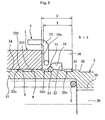
- overlapping allowance herein indicates the maximum width H of a cross-sectional region of the register ring 7, which is delimited by the profile of the outer circumferential surface of the plunger on the forward side of the engagement grooves 33a to 33d, as shown in Fig. 11 .
- the outer circumferential surface of the annular projecting portion 37 corresponds to the "outer circumferential surface of the plunger on the forward side.”
- the cylindrical surface 34 corresponds thereto.
- a ratio H/P of the maximum width H to the wire diameter P of the register ring 7 (more specifically, the ring portion 71) is set at 30 to 50%.
- the maximum width H is identical with a depth of the engagement groove in the case where the register ring 7 is fitted into any of the engagement grooves 33a to 33d to reach its deepest portion.
- the overlapping allowance is smaller than 30% of the wire diameter D, the register ring 7 is likely to pass over a forward side of the outer circumferential surface of each of the engagement grooves 33a to 33d when a backward force is applied to the plunger 3. As a result, there is a possibility that the backward movement may be insufficiently regulated.
- the overlapping allowance exceeds 50% of the wire diameter D, it becomes difficult to cancel the initial set state, resulting in complicated engine assembly. Accordingly, the ratio H/P is required to be set at 50% or less of the wire diameter D.
- the register ring 7 increases its diameter while traveling between the engagement grooves, and has the maximum diameter when passing over the outer circumferential surface of the plunger 3 (in this embodiment, the cylindrical surface 34). If the maximum bending stress generated in the register ring 7 when the register ring 7 has the maximum diameter is smaller than 500 N/mm 2 , the backward movement regulating force generated in the register ring 7 becomes insufficient in consideration of dimensional tolerances of the register ring 7, the engagement grooves 33a to 33d and the like. As a result, reliable backward movement regulation is impeded.
- the projection ability of the plunger 3 (the above-mentioned characteristic II) can be realized by setting the maximum bending stress generated in the register ring 7 when the register ring 7 has the maximum diameter at 1700 N/mm 2 or less. With a bending stress exceeding 1700 N/mm 2 or less, a sliding resistance generated when the plunger 3 outwardly projects is remarkably increased to degrade the followability of the plunger to variation in chain tension.
- the maximum bending stress of the register ring 7 is set within the range of 500 to 1700 N/mm 2 .
- a material of the register ring 7 has a tensile strength of 1000 N/mm 2 or higher.
- the tensile strength is smaller than 1000 N/mm 2 , a sufficient fatigue resistance of the register ring 7 cannot be obtained to lower its durability.
- the strength of the register ring 7 becomes unstable when the plunger 3 is significantly pushed into the cylinder portion 11 due to a delay in oil feeding at engine start to apply an impact load on the register ring 7.
- the upper limit of the tensile strength of the material of the register ring 7 is preferably set at 3400 N/mm 2 or less, desirably, 2400 N/mm 2 or less in view of the cost, the availability and the like.
- silicon-chromium steel oil-tempered wire for valve spring (SWOSC-V) satisfies all the above-described conditions, i.e., the bending stress (500 to 1700 N/mm 2 ) and the tensile strength (1000 N/mm 2 or higher).
- a material of the register ring 7 is required to be selected from the group of materials having the maximum bending stress (the bending stress at the time when the register ring 7 has the maximum diameter) of 70% or less of the tensile strength of the material.
- the oil-tempered wire for valve spring SWOSC-V
- the register ring 7 having an inner diameter ⁇ of 13 is formed of a wire material having a wire diameter ⁇ of 1.
- the register ring 7 is idealized as a C-shaped curved beam shown in Fig. 9 .
- a force P is applied onto both ends of the beam in a direction perpendicular to a line connecting the end and the center thereof, an internal energy U accumulated in the beam is expressed by the following formula.
- U ⁇ 0 s ⁇ M 2 2 ⁇ EI z ⁇ ds
- a deflection ⁇ is calculated by the following formula.
- the maximum bending stress is generated at a point on the diameter opposite to the ends of the wire material.
- ⁇ max 64 ⁇ Pr / ⁇ ⁇ d 3
- This obtained value corresponds to 70% of the tensile strength, i.e., about 2100 (N/mm 2 ), of the oil-tempered wire for valve spring (SWOSC-V) having a wire diameter ⁇ of 1.00 (mm). Consequently, it is confirmed that the maximum bending stress of an actual register ring corresponds to 70% or less of its tensile strength.
- a significant difference equal to or larger than a measurement error is not observed between before and after the repeated load test.
- a difference falls within the range of 0.2% of the initial inner diameter. Based on this result, it is confirmed that a permanent strain caused by the repeated use does not remain in the register ring 7 and therefore the register ring 7 has sufficient strength.
- the operation of the register ring 7 for increasing its diameter is performed on assembly or when the register ring 7 is opened at the initial set, and is therefore performed only several times in a normal use.
- the chain tensioner itself is tested under the following conditions; load amplitude: 100 N to/from 1000 N; frequency shift: 120 Hz; lubrication state: oil application; temperature for evaluation: room temperature; and the number of application of the load amplitude: 1 x 10 7 .
- load amplitude 100 N to/from 1000 N
- frequency shift 120 Hz
- lubrication state oil application
- temperature for evaluation room temperature
- the number of application of the load amplitude 1 x 10 7 .
- the amount of wear is 10 ⁇ m or less on either the lock surface 331 or the first stopper 21. Therefore, no particular problem is generated in terms of the durability.
- the chain tensioner is attached to an actual engine, and a similar test is conducted with no oil supply (where the number of engine revolutions: 2000 r/min; and endurance time: 200 hours). Even in this case, the amount of wear is similarly 10 ⁇ m or less, and no particular problem is generated.
- the register ring is formed of a steel material having a tensile strength of 1000 to 3500 N/mm 2 , a fatigue life of the register ring can be prolonged to provide a chain tensioner having high durability.
- the overlapping allowance of the register ring with respect to the engagement grooves of the register ring is set at 30 to 50% of a wire diameter of the register ring.
- the maximum bending stress of the register ring having an increased diameter between the engagement grooves is set at 500 to 1700 N/mm 2 . Therefore, the backward movement regulation of the plunger at engine stop can be ensured. Moreover, the followability of the plunger to variation in chain tension can be enhanced. Accordingly, the chain tensioner having good operational stability can be provided.
Landscapes
- Engineering & Computer Science (AREA)
- General Engineering & Computer Science (AREA)
- Mechanical Engineering (AREA)
- Devices For Conveying Motion By Means Of Endless Flexible Members (AREA)
Claims (2)
- Kettenspanner umfassend:ein zylindrisches Gehäuse (1) mit einem geschlossenen Ende;einen Kolben (3), der verschiebbar im Gehäuse (1) an einem inneren Umfang (1a) des Gehäuses (1) eingepasst ist;eine Rückstellfeder (5), um dem Kolben eine nach außen gerichtete Vorsprungsfähigkeit zu verleihen;eine Vielzahl von Eingriffsnuten (33a-33d), die an einem äußeren Umfang des Kolbens (3) gebildet ist;einen ersten Anschlag (21), der an dem inneren Umfang (1a) des Gehäuses (1) gebildet ist; undeinen Einstellring (7), der elastisch seinen Durchmesser vergrößern und verkleinern kann, und der mit den Eingriffsnuten (33a-33d) in Eingriff ist,wobei jeder der Eingriffsnuten (33a-33d) mit dem ersten Anschlag (21) durch den Einstellring (7) in Eingriff kommt, um die nach hinten gerichtete Bewegung des Kolbens (3) einzustellen, wobeider Einstellring (7) aus einem Stahlmaterial gebildet ist, der eine Zugfestigkeit von 1000 bis 3500 N/mm2 aufweist, eine Überlappungstoleranz des Einstellringes (7) bezüglich der Eingriffsnuten (33a-33d) des Kolbens (3) im Bereich von 30 bis 50 % eines Drahtdurchmessers des Einstellringes (7) eingestellt ist, dadurch gekennzeichnet dass eine maximale Biegebelastung des Einstellringes (7), die erzeugt wird, wenn der Einstellring (7) einen vergrößerten Durchmesser hat, wenn er zwischen den Eingriffsnuten (33a-33d) positioniert ist, in einem Bereich von 500 bis 1700 N/mm2 eingestellt ist, und die maximale Biegebelastung 70% der Zugfestigkeit des Materials oder weniger ist.
- Kettenspanner nach Anspruch 1, wobei der Einstellring (7) aus einem ölgehärteten Draht gebildet ist.
Applications Claiming Priority (2)
| Application Number | Priority Date | Filing Date | Title |
|---|---|---|---|
| JP2002303031A JP2004138152A (ja) | 2002-10-17 | 2002-10-17 | チェーンテンショナ |
| JP2002303031 | 2002-10-17 |
Publications (3)
| Publication Number | Publication Date |
|---|---|
| EP1411271A2 EP1411271A2 (de) | 2004-04-21 |
| EP1411271A3 EP1411271A3 (de) | 2006-12-06 |
| EP1411271B1 true EP1411271B1 (de) | 2010-12-15 |
Family
ID=32040836
Family Applications (1)
| Application Number | Title | Priority Date | Filing Date |
|---|---|---|---|
| EP03256509A Expired - Lifetime EP1411271B1 (de) | 2002-10-17 | 2003-10-15 | Kettenspanner |
Country Status (4)
| Country | Link |
|---|---|
| US (1) | US6935978B2 (de) |
| EP (1) | EP1411271B1 (de) |
| JP (1) | JP2004138152A (de) |
| DE (1) | DE60335334D1 (de) |
Families Citing this family (41)
| Publication number | Priority date | Publication date | Assignee | Title |
|---|---|---|---|---|
| JP3929679B2 (ja) * | 2000-06-26 | 2007-06-13 | Ntn株式会社 | チェーンテンショナ |
| DE10197231B4 (de) * | 2001-12-10 | 2015-02-19 | Ntn Corp. | Kettenspannvorrichtung |
| US7571632B2 (en) | 2002-12-10 | 2009-08-11 | Ntn Corporation | Chain Tensioner |
| JP4282424B2 (ja) * | 2003-08-29 | 2009-06-24 | Ntn株式会社 | チェーンテンショナ |
| EP1653121B1 (de) * | 2004-10-28 | 2008-10-29 | Ntn Corporation | Kettenspannvorrichtung |
| JP3916635B2 (ja) | 2005-01-25 | 2007-05-16 | 株式会社椿本チエイン | 油圧式チェーンテンショナ |
| DE102006026702B4 (de) * | 2005-06-13 | 2017-10-19 | Borgwarner Morse Tec Japan K.K. | Spanner |
| JP4951160B2 (ja) * | 2006-06-29 | 2012-06-13 | ボルグワーナー・モールステック・ジャパン株式会社 | テンショナ |
| WO2008038359A1 (en) * | 2006-09-28 | 2008-04-03 | Daido Kogyo Co., Ltd. | Chain tensioner |
| WO2009015174A1 (en) * | 2007-07-23 | 2009-01-29 | Borgwarner Inc. | Modular hydraulic tensioner with ratchet |
| JP5244265B2 (ja) * | 2008-07-22 | 2013-07-24 | ボーグワーナー インコーポレーテッド | クリップタイプテンショナ |
| JP2010091055A (ja) * | 2008-10-09 | 2010-04-22 | Ntn Corp | チェーンテンショナ |
| JP5102175B2 (ja) * | 2008-10-22 | 2012-12-19 | Ntn株式会社 | チェーンテンショナの製造方法 |
| US8393987B2 (en) | 2008-10-22 | 2013-03-12 | Ntn Corporation | Chain tensioner |
| JP4480789B1 (ja) * | 2009-07-21 | 2010-06-16 | 株式会社椿本チエイン | チェーンテンショナ |
| JP2011231881A (ja) * | 2010-04-28 | 2011-11-17 | Tsubakimoto Chain Co | ボール式テンショナ |
| JP4938102B2 (ja) * | 2010-05-21 | 2012-05-23 | 株式会社椿本チエイン | チェーンテンショナ |
| EP2395259B1 (de) * | 2010-06-11 | 2012-11-07 | iwis motorsysteme GmbH & Co. KG | Spannvorrichtung mit Rastspange |
| JP5705033B2 (ja) * | 2011-06-02 | 2015-04-22 | 株式会社椿本チエイン | リング式テンショナ |
| JP5926002B2 (ja) * | 2011-06-08 | 2016-05-25 | Ntn株式会社 | チェーンテンショナ |
| DE102012001074B4 (de) * | 2012-01-20 | 2021-09-23 | Iwis Motorsysteme Gmbh & Co. Kg | Spannvorrichtung mit einem einen Rampenbereich aufweisenden Entriegelungselement |
| DE112014002052T5 (de) * | 2013-05-24 | 2016-03-24 | Borgwarner Inc. | Reihenanordnung aus hydraulischem Kettenspanner und Ratsche |
| JP6190322B2 (ja) * | 2014-06-06 | 2017-08-30 | 株式会社椿本チエイン | チェーンテンショナ |
| US10400870B2 (en) | 2014-10-29 | 2019-09-03 | Borgwarner Inc. | Valvular paths |
| DE112015004282T5 (de) * | 2014-10-29 | 2017-06-22 | Borgwarner Inc. | Wirbelkanal |
| JP6263150B2 (ja) * | 2015-05-29 | 2018-01-17 | 株式会社椿本チエイン | テンショナ |
| JP6386978B2 (ja) * | 2015-07-31 | 2018-09-05 | 株式会社椿本チエイン | テンショナ |
| DE102015215420A1 (de) * | 2015-08-13 | 2017-02-16 | Schaeffler Technologies AG & Co. KG | Linearspanner |
| DE102016207782A1 (de) * | 2016-05-04 | 2017-11-09 | Schaeffler Technologies AG & Co. KG | Hydraulische Spannvorrichtung für einen Kettentrieb |
| DE102016207793A1 (de) * | 2016-05-04 | 2017-11-09 | Schaeffler Technologies AG & Co. KG | Hydraulische Spannvorrichtung für einen Kettentrieb |
| DE102016221797B4 (de) * | 2016-11-08 | 2020-03-26 | Schaeffler Technologies AG & Co. KG | Spannvorrichtung |
| US10738861B2 (en) * | 2016-12-20 | 2020-08-11 | Borgwarner Inc. | Control of hydraulic tensioner tuning using hole size in piston nose |
| JP2020504271A (ja) * | 2017-01-11 | 2020-02-06 | ボーグワーナー インコーポレーテッド | 油圧テンショナ用戻り防止システム |
| JP6518282B2 (ja) * | 2017-03-28 | 2019-05-22 | 株式会社Subaru | オイル供給装置 |
| JP6882679B2 (ja) * | 2017-07-07 | 2021-06-02 | 株式会社椿本チエイン | テンショナ |
| US10384631B2 (en) * | 2017-07-10 | 2019-08-20 | Caterpillar Inc. | Guard assembly for truck body |
| DE112018005643T5 (de) * | 2018-01-10 | 2020-07-09 | Borgwarner Inc. | Rückhaltung von kettenspannerkolben |
| JP7100467B2 (ja) * | 2018-03-05 | 2022-07-13 | Ntn株式会社 | チェーンテンショナ |
| US10871207B2 (en) * | 2018-08-02 | 2020-12-22 | Borgwarner, Inc. | Hydraulic tensioner expandable clip lock |
| WO2021044028A1 (de) * | 2019-09-05 | 2021-03-11 | Iwis Motorsysteme Gmbh & Co. Kg | Spannvorrichtung mit einem einzelnen sicherungsring |
| US11828206B1 (en) * | 2022-11-14 | 2023-11-28 | Borgwarner Inc. | Hydraulic tensioner with external pin and ratchet mechanism |
Family Cites Families (7)
| Publication number | Priority date | Publication date | Assignee | Title |
|---|---|---|---|---|
| JP2613601B2 (ja) * | 1987-09-25 | 1997-05-28 | 日産自動車株式会社 | 高強度スプリング |
| US5931754A (en) * | 1995-06-10 | 1999-08-03 | Ina Walzlager Schaeffler Ohg | Tensioner for a power transmitting member of an internal combustion engine |
| US5700214A (en) * | 1996-03-20 | 1997-12-23 | Borg-Warner Automotive, Inc. | Hydraulic tensioner with locking mechanism |
| US5967920A (en) * | 1997-10-09 | 1999-10-19 | Borg-Warner Automotive, Inc. | Hydraulic tensioner with a bore cup |
| JP3670911B2 (ja) * | 1999-11-19 | 2005-07-13 | Ntn株式会社 | チェーンテンショナ |
| JP3987270B2 (ja) * | 2000-06-14 | 2007-10-03 | Ntn株式会社 | チェーンテンショナ |
| JP2001355961A (ja) | 2000-06-15 | 2001-12-26 | Sanyo Electric Co Ltd | 冷蔵庫 |
-
2002
- 2002-10-17 JP JP2002303031A patent/JP2004138152A/ja active Pending
-
2003
- 2003-10-15 EP EP03256509A patent/EP1411271B1/de not_active Expired - Lifetime
- 2003-10-15 DE DE60335334T patent/DE60335334D1/de not_active Expired - Lifetime
- 2003-10-16 US US10/685,703 patent/US6935978B2/en not_active Expired - Lifetime
Also Published As
| Publication number | Publication date |
|---|---|
| JP2004138152A (ja) | 2004-05-13 |
| EP1411271A2 (de) | 2004-04-21 |
| US6935978B2 (en) | 2005-08-30 |
| DE60335334D1 (de) | 2011-01-27 |
| EP1411271A3 (de) | 2006-12-06 |
| US20040138018A1 (en) | 2004-07-15 |
Similar Documents
| Publication | Publication Date | Title |
|---|---|---|
| US6935978B2 (en) | Chain tensioner | |
| JP3929679B2 (ja) | チェーンテンショナ | |
| US8221274B2 (en) | Chain tensioner | |
| EP0908646B1 (de) | Hydraulischer Kettenspanner mit einer tiefgezogenen, topfförmigen Zylinderbüchse | |
| US7775921B2 (en) | Chain tensioner | |
| US8146340B2 (en) | Link chain | |
| EP0952375A2 (de) | Hydraulische Spannvorrichtung mit einem Überdruckventil. | |
| EP2008001A1 (de) | Ratschenmechanimus für einen kettenantrieb | |
| ITMI942215A1 (it) | Miglioramenti nei tenditori per cinghie di trasmissione | |
| EP2801736A1 (de) | Hydraulischer selbstspanner | |
| US8007384B2 (en) | Hydraulic tensioner | |
| EP1915549B1 (de) | Langer mechanischer spanner mit nachgiebiger blattfeder | |
| US20060270500A1 (en) | Chain tensioner | |
| KR20190121684A (ko) | 텐셔너 | |
| US20130331212A1 (en) | Tensioner | |
| JP2019206981A (ja) | テンショナ | |
| US7223190B2 (en) | Hydraulic chain tensioner | |
| US11339855B2 (en) | Tensioner | |
| JP3987270B2 (ja) | チェーンテンショナ | |
| JP3929678B2 (ja) | チェーンテンショナ | |
| JP4708382B2 (ja) | チェーンテンショナ | |
| EP1887246B1 (de) | Spiralfeder | |
| JP3929680B2 (ja) | チェーンテンショナ | |
| US20060163786A1 (en) | Spring damper | |
| JP7300549B1 (ja) | オートテンショナ |
Legal Events
| Date | Code | Title | Description |
|---|---|---|---|
| PUAI | Public reference made under article 153(3) epc to a published international application that has entered the european phase |
Free format text: ORIGINAL CODE: 0009012 |
|
| AK | Designated contracting states |
Kind code of ref document: A2 Designated state(s): AT BE BG CH CY CZ DE DK EE ES FI FR GB GR HU IE IT LI LU MC NL PT RO SE SI SK TR |
|
| AX | Request for extension of the european patent |
Extension state: AL LT LV MK |
|
| PUAL | Search report despatched |
Free format text: ORIGINAL CODE: 0009013 |
|
| AK | Designated contracting states |
Kind code of ref document: A3 Designated state(s): AT BE BG CH CY CZ DE DK EE ES FI FR GB GR HU IE IT LI LU MC NL PT RO SE SI SK TR |
|
| AX | Request for extension of the european patent |
Extension state: AL LT LV MK |
|
| 17P | Request for examination filed |
Effective date: 20070326 |
|
| AKX | Designation fees paid |
Designated state(s): DE |
|
| 17Q | First examination report despatched |
Effective date: 20070718 |
|
| GRAP | Despatch of communication of intention to grant a patent |
Free format text: ORIGINAL CODE: EPIDOSNIGR1 |
|
| GRAS | Grant fee paid |
Free format text: ORIGINAL CODE: EPIDOSNIGR3 |
|
| GRAA | (expected) grant |
Free format text: ORIGINAL CODE: 0009210 |
|
| RIN1 | Information on inventor provided before grant (corrected) |
Inventor name: SATO, SEIJIC/O NTN CORPORATION Inventor name: HAYAKAWA, HISASHIC/O NTN CORPORATION |
|
| AK | Designated contracting states |
Kind code of ref document: B1 Designated state(s): DE |
|
| REF | Corresponds to: |
Ref document number: 60335334 Country of ref document: DE Date of ref document: 20110127 Kind code of ref document: P |
|
| PLBE | No opposition filed within time limit |
Free format text: ORIGINAL CODE: 0009261 |
|
| STAA | Information on the status of an ep patent application or granted ep patent |
Free format text: STATUS: NO OPPOSITION FILED WITHIN TIME LIMIT |
|
| 26N | No opposition filed |
Effective date: 20110916 |
|
| REG | Reference to a national code |
Ref country code: DE Ref legal event code: R097 Ref document number: 60335334 Country of ref document: DE Effective date: 20110916 |
|
| PGFP | Annual fee paid to national office [announced via postgrant information from national office to epo] |
Ref country code: DE Payment date: 20220831 Year of fee payment: 20 |
|
| REG | Reference to a national code |
Ref country code: DE Ref legal event code: R071 Ref document number: 60335334 Country of ref document: DE |