EP1411282A1 - Drehende Dichtung für einen Kugelhahn - Google Patents
Drehende Dichtung für einen Kugelhahn Download PDFInfo
- Publication number
- EP1411282A1 EP1411282A1 EP20030023269 EP03023269A EP1411282A1 EP 1411282 A1 EP1411282 A1 EP 1411282A1 EP 20030023269 EP20030023269 EP 20030023269 EP 03023269 A EP03023269 A EP 03023269A EP 1411282 A1 EP1411282 A1 EP 1411282A1
- Authority
- EP
- European Patent Office
- Prior art keywords
- rotatable
- valve
- passage
- ball
- seal
- Prior art date
- Legal status (The legal status is an assumption and is not a legal conclusion. Google has not performed a legal analysis and makes no representation as to the accuracy of the status listed.)
- Granted
Links
- 239000012530 fluid Substances 0.000 claims abstract description 65
- 210000001124 body fluid Anatomy 0.000 claims description 12
- 239000010839 body fluid Substances 0.000 claims description 12
- 238000004891 communication Methods 0.000 claims description 9
- 238000000034 method Methods 0.000 claims description 8
- 230000008878 coupling Effects 0.000 description 5
- 238000010168 coupling process Methods 0.000 description 5
- 238000005859 coupling reaction Methods 0.000 description 5
- 230000000712 assembly Effects 0.000 description 2
- 238000000429 assembly Methods 0.000 description 2
- 230000000295 complement effect Effects 0.000 description 2
- 230000006835 compression Effects 0.000 description 2
- 238000007906 compression Methods 0.000 description 2
- 239000000463 material Substances 0.000 description 2
- 238000007789 sealing Methods 0.000 description 2
- 230000006978 adaptation Effects 0.000 description 1
- 230000033228 biological regulation Effects 0.000 description 1
- 230000000903 blocking effect Effects 0.000 description 1
- 230000007423 decrease Effects 0.000 description 1
- 230000003116 impacting effect Effects 0.000 description 1
- 230000013011 mating Effects 0.000 description 1
- 230000002265 prevention Effects 0.000 description 1
- 230000001737 promoting effect Effects 0.000 description 1
- 238000003466 welding Methods 0.000 description 1
Images


Classifications
-
- F—MECHANICAL ENGINEERING; LIGHTING; HEATING; WEAPONS; BLASTING
- F16—ENGINEERING ELEMENTS AND UNITS; GENERAL MEASURES FOR PRODUCING AND MAINTAINING EFFECTIVE FUNCTIONING OF MACHINES OR INSTALLATIONS; THERMAL INSULATION IN GENERAL
- F16K—VALVES; TAPS; COCKS; ACTUATING-FLOATS; DEVICES FOR VENTING OR AERATING
- F16K5/00—Plug valves; Taps or cocks comprising only cut-off apparatus having at least one of the sealing faces shaped as a more or less complete surface of a solid of revolution, the opening and closing movement being predominantly rotary
- F16K5/06—Plug valves; Taps or cocks comprising only cut-off apparatus having at least one of the sealing faces shaped as a more or less complete surface of a solid of revolution, the opening and closing movement being predominantly rotary with plugs having spherical surfaces; Packings therefor
- F16K5/0626—Easy mounting or dismounting means
- F16K5/0642—Easy mounting or dismounting means the spherical plug being insertable from one and only one side of the housing
Definitions
- the present invention relates to fluid handling products, and, in particular, to ball valves utilized to regulate the flow of fluid materials.
- Valves are well-known components of various fluid handling systems, including systems used in agricultural, pharmaceutical, and other such industries, and other related fluid handling applications.
- Ball valves have proven to be particularly useful in these fluid handling systems, specifically for regulation of the flow of the fluid materials through the system and to the ultimate end use.
- Such ball valve assemblies are easily inserted into the fluid handling systems; however, the assembly of such ball valve assemblies is rather problematic.
- valve housing generally includes two or more pieces that fasten together mechanically by bolts or by screw threads connecting the housing components together, or by welding, riveting or other such means of mechanical connection. Creating the mechanical connection requires significant force which may stress both the valves and the assembly equipment, negatively impacting their performance.
- a ball valve assembly having two end bodies selectively detachable from each other with each end body defining a fluid conveying bore is provided with a rotatable ball valve element cut off at an angle which facilitates assembly.
- the rotatable ball valve element is disposed within the end bodies and defines a central passage having an axis, with the rotatable ball valve element having an open position in which the central passage is aligned with the fluid conveying bores and a closed position in which the passage is not aligned with the fluid conveying bores.
- the ball valve assembly also includes a pair of seals, with a seal disposed in each end body and in selective abutting engagement with the rotatable ball valve element. The structure of the rotatable ball valve element is controlled such that the ball valve assembly is assembled with the ball in an open position, thereby substantially eliminating the significant force normally required for assembly of the ball valve assembly.
- the present invention provides a valve assembly for controlling a flow of fluid including a first end body including a fluid conveying bore, a second end body selectively detachable from the first end body and including at least one fluid conveying bore therethrough, a rotatable ball valve element having a radius, and at least a pair of seal members with a seal member disposed in the first end body and a second seal member disposed in the second end body.
- the rotatable ball valve element has a first position wherein the first end body fluid conveying bore and the second end body fluid conveying bore are not in fluid communication, and a second position wherein the first end body fluid conveying bore and the second end body fluid conveying bore are in fluid communication.
- the seals are structured and arranged to substantially prevent fluid flow when the rotatable ball valve element is in the first position, with each seal defining a seal contact area wherein the radius of the rotatable ball valve element contacts the seal when the rotatable ball valve element is in its first position.
- the rotatable ball valve element defines a passage having an axis, an axial distance being defined between a line perpendicular to the axis and the seal contact area and a radial distance being defined between the axis and the seal contact area, the radial distance being perpendicular to the axial distance, and wherein a ratio of the radial distance to the axial distance has a numerical value of less than 1.
- the present invention further provides a rotatable element for a ball valve assembly having at least one body portion for the rotatable element and associated seals.
- the rotatable element includes a body having a generally spherical outer surface and a radius at which the body contacts the seals to define a seal contact area, the body defines a passage having a central axis, and the rotatable element defines a centerline co-planar and perpendicular to the passage central axis.
- An axial distance is defined between the centerline and the seal contact area, and a radial distance is defined between the passage central axis and the seal contact area; wherein a ratio of the radial distance to the axial distance has a numerical value of less than 1.
- the present invention further provides a method of assembling a ball valve for use in fluid handling applications, the method includes providing a valve body having a first portion and a second portion, each portion having a port therethrough with the ports being axially aligned with the valve body when assembled, providing a rotatable element having a passage therethrough, rotating the rotatable element into a position wherein the passage aligns with the ports of the valve body, inserting the rotatable element between the first portion and the second portion of the valve body, securing the first portion and the second portion of the valve body together with a securement mechanism requiring limited force to be applied to the securement mechanism and the portions, compressing the rotatable element therebetween, and rotating the rotatable element into a position wherein the passage is not aligned with the ports.
- Figure 1 is a perspective view of an embodiment of a bolted ball valve assembly which is used in accordance with the present invention
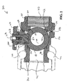
- Figure 2 is a cross-sectional front view taken along line 2-2 of the bolted ball valve assembly of Figure 1, wherein portions of a mating fluid handling system component are shown in dashed lines;
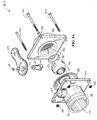
- Figure 3A is an exploded view of the bolted ball valve assembly of Figure 1, as viewed from a left front perspective;
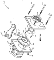
- Figure 3B is an exploded view of the bolted ball valve assembly of Figure 1, as viewed from a right rear perspective;
- Figure 4 is an enlarged sectional view of the ball of the bolted ball valve assembly, the ball having being rotated into a position in which the central passage is aligned with the bores of the valve body;
- Figure 5 is an enlarged sectional view of the ball of the bolted ball valve assembly, the ball having being rotated into a position in which the central passage is not aligned with the bores of the valve body.
- Bolted ball valve assembly 20 is shown in Figure 1 as including a pair of end bodies 22 and 24 joined by a plurality of bolts 26 through end body 22 and received by nuts 28 in complementary end body 24.
- End body 24 further includes projection 30 thereon having bore 32 through projection 30 with female threads 34 in bore 32 for receipt of a complementary male threaded element, such as, for example, a coupling or hose fitting.
- End portion 22 further includes connector section 36 extending from end portion 22 and having large groove 38 formed in connector section 36 for receipt of a connector from an external fluid handling device, such as a hose, or tank fitting, or other coupling.
- Such a connector or coupling device is shown in phantom in Figure 2, specifically coupling arms 74, which are shown in phantom in their connected position to valve 20; coupling arms 74 are used to connect valve 20 to another fluid handling device: Pivotably disposed at the top of valve 20 is user actuated handle 40 for imparting rotary force to a rotatable valve element, or ball, as described below.
- Figure 2 shows the interior of valve 20, with bore 32 of end body 24 being in fluid communication with fluid conveying bore 42.
- End body 24 defines fluid conveying bore 42, and on opposite side end body 22 defines fluid conveying bore 44.
- Seal 58 is disposed between end bodies 22 and 24 and serves to retain fluid inside valve cavity 48 and prevent fluid from escaping between end bodies 22 and 24.
- Ball 46 is disposed such that a majority of the ball is housed within cavity 48 of end body 22 and a smaller portion extending into fluid conveying bore 42 of end body 24.
- Ball 46 has a substantially spherical outer surface 50 with an upwardly facing portion defining recess 52.
- a pair of seal elements 54 and 56 are disposed within fluid conveying bores 42 and 44 and form an abutting engagement with ball 46 to prevent fluid flow around ball 46 when ball 46 is in the closed position.
- Ball 46 further defines passage 60 (along axis 61, Figure 4) which is capable of alignment with fluid conveying bores 42 and 44 to allow fluid to pass through valve 20.
- ball 46 To facilitate passage of fluid through valve 20, ball 46 must be rotated from the position shown in Figure 2 to an open position-( Figures 3A and 3B), this being accomplished by user movement of handle 40 which is connected to rotation device 62 via head portion 64 that is received within recess 52 of ball 46.
- Rotation device 62 is disposed within bore 66 of end body 22 and is connected to handle 40 via bolt 68. As with the connection between end bodies 22 and 24, a pair of seals 70 and 72 are disposed within end body 22 around rotation device 62 to prevent fluid leakage through bore 66 and around device 62.
- valve 20 is shown in an exploded view with better views of the individual parts of valve assembly 20. Further shown in Figures 3A and 3B is bolt hole 76 in rotation device 62 for receipt of bolt 68 and opening 78 in handle 40 to receive rotation device 62. Both end bodies 22 and 24 have abutting surfaces with end body 22 having surface 82 and end body 24 having abutting face surface 80 which abut at vertical interface 84 ( Figure 1). It is at this interface 84 that a potential leak of fluid could occur and therefore, seal 58 is included in valve assembly 20.
- Ball 46 is shown in an open position in Figures 3A and 3B, or in a position wherein fluid is capable of flowing through valve 20 via fluid conveying bores 42 and 44 and through passage 60 of ball 46 since passage 60 is aligned with fluid conveying bores 42 and 44.
- Figures 4 and 5 show ball 46 in both an "open” position in which central passage 60 is aligned with fluid conveying bores 42 and 44 of end bodies 22 and 24 and a “closed” position in which central passage 60 is not aligned with the fluid conveying bores of end bodies 22 and 24, with the position of ball 46 relative to seals 54 and 56 also being shown.
- Ball 46 is generally spherical shaped but is truncated at inlet port 96 and outlet port 98 of passage 60, which alternatively may be rotated 180°. Due to the truncation, ball 46 is generally appears to be taller than wide when viewed in the open position.
- Such truncation decreases the distance from inlet port 96 to outlet port 98 and provides a space between ball 46 and end bodies 22 and 24 such that seals 54 and 56 are maintained in the proper position but are not subject to the same compressive forces when ball 46 is in the open position as when ball 46 is in the closed position.
- the amount of truncation of ball 46, while providing the space, is limited by the requirement that enough of ball 46 remains such that there is sufficient distance between inlet port 96 and outlet port 98 to ensure that there is enough area for seals 54 and 56 to contact ball 46 radially in all directions when ball 46 is rotated to the closed position.
- Ball 46 defines center point 86 at the intersection of line 88 and line 90, with line 88 extending from the uppermost portion of seal 54 to the lowermost portion of seal 56 while line 90 extends from the uppermost portion of seal 56 to the lowermost portion of seal 54.
- Upper and lower are defined as “upper” being proximate the upper portion of valve 20 or where handle 40 is attached and “lower” being defined as the opposite.
- Both lines 88 and 90 are twice the radius of ball 46, with center point 86 being the point from which the radius would be measured. Center point 86 is useful as a reference point for defining distances and angles, as described below.
- seal contact areas 92 and 94 disposed on seals 54 and 56, respectively. These contact areas 92 and 94 are best seen in Figure 5 wherein they are the points at which ball 46 comes into compressive contact with each seal 54 and 56 when ball 46 is rotated to the closed position, or where the radius of ball 46 (as shown in lines 88 and 90) meets seals 54 and 56. Since seal contact areas 92 and 94 are contacted in the closed position, they appear to be "inside" seals 54 and 56 due to the compression exerted on seals 54 and 56 when ball 46 is rotated to the closed position.
- angle ⁇ must be controlled to permit such assembly.
- angle ⁇ is defined between a line extending from center point 86 coplanarly with axis 61 and line 90.
- Another way of defining angle ⁇ is that the tangent of angle ⁇ is equal to the numerical value of distance C divided by the numerical value of distance A.
- distance A is the axial distance from a line through center point 86 and perpendicular to axis 61 to a seal contact area of either seal 54 or 56.
- distance A is shown as extending to seal contact area 92 of seal 54, it may be rotated 180° such that it extends to seal contact area 94.
- Distance C is defined as the radial distance from a line coplanar with axis 61 and through center point 86 to a seal contact area, either seal contact area 92 or seal contact area 94.
- distance B is measured from a line through center point 86 and perpendicular to axis 61 to either inlet 96 or outlet 98.
- the tangent of angle ⁇ is equal to the numerical value of distance C divided by the numerical value of distance A.
- the tangent of ⁇ must be equal to less than 1, or angle ⁇ must be less than 45°, therefore, distance C is less than distance A. Since angle ⁇ is less than 45°, it can be said that lines 88 and 90 are not perpendicular to each other since twice angle ⁇ is less than 90°.
- valve assembly 20 is capable of being mechanically assembled with ball 46 being in the open position and thereby requiring less force for the assembly process, and yet ensuring that fluid is unable to flow around ball 46 when it is rotated into the closed position.
- seals 54 and 56 are shown as not contacting ball 46 when in the open position of Figure 4, seals 54 and 56 may contact ball 46 in the open position, even though ball 46 is not exerting the same compressive forces, as in the closed position, and not contacting seal contact areas 92 and 94.
- Contact between ball 46 and seals 54 and 56, when ball 46 is in the open position is determined by distance B, or the distance to the inlet or outlet ports. If distance B is only very slightly less than distance A, then ball 46 will contact seals 54 and 56 in the open position, but will not be exerting compressive forces on the seals. However, as the difference between distance A and distance B increases, then a point is reached at which ball 46 will not contact seals 54 and 56 when ball 46 is in the open position.
- seals 54 and 56 are compressed when ball 46 is in its closed position, seal contact areas 92 and 94 are not moved as a result of the compression, and, thus, distances A and C remain unchanged. Specifically, compressive contact between ball 46 and seals 54 and 56 may cause additional areas of seals 54 and 56 to contact ball 46, but the axial and radial distances from center point 86 to seal contact areas 92 and 94 would not change since ball 46 does not change shape or geometry. Likewise the radius of ball 46, or half of each line 88 and 90, would not change. However, seals 54 and 56 are sufficiently flexible to conform to ball 46 when in the closed position to ensure a fluid tight seal around ball 46 thereby substantially preventing fluid flow around ball 46.
- Valve assembly 20 is assembled by placing seal 56 in the proper position and ball 46 against it within the cavity in second body portion 22 and in an open position, then placing seal 54 against ball 46 and against end body 24. Since the majority of ball 46 is held by end body 22, the rotation device 62 is inserted into bore 66 and handle 40 attached thereto. Bolts 26 and nuts 28 are then placed in the appropriate positions and connected, thereby causing seals 54 and 56 to contact ball 46, as well as be compressed against respective end bodies 22 and 24. Thus, valve assembly 20 is assembled with the ball in the open position; however, ball 46 may then be rotated to the closed position, if desired, for possible assembly of valve 22 other fluid handling components.
- seals 54 and 56 contact ball 46 in the open position, the pressure on seals 54 and 56 is less when ball 46 is in the open position than in the closed position since fluid flow is desired when the ball is in the open position, thus less pressure, and fluid flow is very undesirable in the closed position, thus greater pressure is required to close possible fluid flow points around ball 46.
- ball 46 is shown as a truncated generally spherical element, other geometric structures may be utilized.
- an elliptical element could be used, with the truncation occurring along the major axis of the elliptical element.
- Other structures, such as, for example ovoid shapes, could also be utilized, provided that the diameter of the truncated element is sufficient to accommodate the necessary port size through the element and that enough of the element remains after truncation such that the inlet port and the outlet port are spaced apart to provide sufficient area for the seals to be compressed by the ball in all radial directions when the ball is rotated to the closed position.
Landscapes
- Engineering & Computer Science (AREA)
- General Engineering & Computer Science (AREA)
- Mechanical Engineering (AREA)
- Taps Or Cocks (AREA)
Applications Claiming Priority (2)
| Application Number | Priority Date | Filing Date | Title |
|---|---|---|---|
| US272192 | 2002-10-15 | ||
| US10/272,192 US6971633B2 (en) | 2002-10-15 | 2002-10-15 | Rotatable seal for ball valve |
Publications (2)
| Publication Number | Publication Date |
|---|---|
| EP1411282A1 true EP1411282A1 (de) | 2004-04-21 |
| EP1411282B1 EP1411282B1 (de) | 2009-03-04 |
Family
ID=32042930
Family Applications (1)
| Application Number | Title | Priority Date | Filing Date |
|---|---|---|---|
| EP03023269A Expired - Lifetime EP1411282B1 (de) | 2002-10-15 | 2003-10-14 | Kugelhahn mit einer drehenden Dichtung |
Country Status (5)
| Country | Link |
|---|---|
| US (1) | US6971633B2 (de) |
| EP (1) | EP1411282B1 (de) |
| AT (1) | ATE424525T1 (de) |
| CA (1) | CA2434333C (de) |
| DE (1) | DE60326415D1 (de) |
Families Citing this family (11)
| Publication number | Priority date | Publication date | Assignee | Title |
|---|---|---|---|---|
| US7745365B2 (en) * | 2007-03-09 | 2010-06-29 | Stone & Webster Process Technology, Inc. | Bathtub-type spent catalyst distributor for effective counter-current regeneration in fluid catalytic cracking units |
| FI120891B (fi) * | 2007-06-01 | 2010-04-15 | Metso Automation Oy | Venttiiliakselin yksinkertainen aksiaalilukitus |
| ATE534018T1 (de) * | 2008-01-31 | 2011-12-15 | Prad Res & Dev Nv | Durchflussmessgerät eingesetzt in einem kugelventil |
| US8312889B2 (en) * | 2009-06-30 | 2012-11-20 | Snyder Industries, Inc. | Combination flow control valve and reverse flow check valve |
| WO2011123865A1 (en) | 2010-04-02 | 2011-10-06 | Sta-Rite Industries, Llc | Air aspiration device |
| US8985145B2 (en) | 2013-03-11 | 2015-03-24 | Snyder Industries, Inc. | Combination flow control valve and reverse flow check valve |
| US9470320B1 (en) | 2013-06-03 | 2016-10-18 | Kelso Technologies Inc. | Ball valve assembly |
| US10179304B2 (en) | 2017-05-26 | 2019-01-15 | Craig V. Winborn | Tank fitting apparatus and method |
| US11713238B2 (en) * | 2020-09-23 | 2023-08-01 | Elkhart Plastics, Inc. | Intermediate bulk container, valve and connector system |
| CN115614512B (zh) * | 2022-11-23 | 2025-11-18 | 郑州康润流体设备有限公司 | 一种多功能过滤阀 |
| US12480584B1 (en) * | 2024-12-02 | 2025-11-25 | Gabriel Max Miller | Clean-in-place shutter valve |
Citations (8)
| Publication number | Priority date | Publication date | Assignee | Title |
|---|---|---|---|---|
| US1330429A (en) * | 1919-01-11 | 1920-02-10 | Robert E Campbell | Valve |
| US3533597A (en) * | 1967-11-29 | 1970-10-13 | Ite Imperial Corp | Floating seal ball valve |
| US4193580A (en) * | 1976-04-06 | 1980-03-18 | Worchester Controls Ag | Plug valve |
| EP0217993A1 (de) * | 1984-09-26 | 1987-04-15 | St Mihiel S.A. | Hahn mit einem drehbaren Küken, sein Zusammenbau und ein Ventil mit einem solchen Hahn |
| AU592473B2 (en) * | 1986-10-14 | 1990-01-11 | Gearhart United Pty Ltd | Kelly cock |
| US5445187A (en) * | 1993-06-22 | 1995-08-29 | Spirax-Sarco Limited | Condensate traps |
| DE19520900A1 (de) * | 1995-06-01 | 1996-12-12 | Rautenkranz Int Hermann | Absperrarmatur für Rohrleitungen |
| US5911405A (en) * | 1997-05-09 | 1999-06-15 | The United States Of America As Represented By The Secretary Of The Navy | Multi-ported diverter valve assembly |
Family Cites Families (14)
| Publication number | Priority date | Publication date | Assignee | Title |
|---|---|---|---|---|
| US3095898A (en) | 1960-12-02 | 1963-07-02 | Jamesbury Corp | Removable ball and seat valve unit |
| US3784155A (en) | 1973-04-13 | 1974-01-08 | Acf Ind Inc | Ball and seat arrangement for ball valve |
| US3827671A (en) | 1973-06-11 | 1974-08-06 | Auto Valve Inc | Low pressure ball valve with annular seal |
| US4411407A (en) | 1981-04-13 | 1983-10-25 | Asahi Yukizai Kogyo Co., Ltd. | Ball valve assembly |
| US4683906A (en) * | 1985-11-29 | 1987-08-04 | Itt Corporation | Trunnion type ball valve |
| US4637421A (en) | 1986-05-15 | 1987-01-20 | Stunkard Gerald A | In-line repairable top entry ball valve |
| WO1991009243A1 (fr) | 1989-12-19 | 1991-06-27 | Asahi Yukizai Kogyo Co., Ltd. | Robinet a tournant spherique |
| NO170239C (no) * | 1990-03-19 | 1992-09-23 | Ingolf Klyde | Kuleventil |
| US5152502A (en) | 1992-01-17 | 1992-10-06 | Itt Corporation | Ball valve subassembly, and means for unitizing such into an integrated assembly |
| US5313976A (en) | 1993-07-26 | 1994-05-24 | Keystone International Holdings, Corp. | Top entry ball valve and method of assembly |
| NO310529B1 (no) * | 1999-02-11 | 2001-07-16 | Ingolf Klyde | Anordning ved kuleventil |
| US6267353B1 (en) | 1999-04-19 | 2001-07-31 | Pbm, Inc. | Self draining valve |
| US20010045231A1 (en) | 1999-06-14 | 2001-11-29 | Gilles Monod | Ball valve with replaceable cartridge insert |
| US6173940B1 (en) | 1999-06-30 | 2001-01-16 | Premier Farnell Corp. | Valve ball configuration |
-
2002
- 2002-10-15 US US10/272,192 patent/US6971633B2/en not_active Expired - Lifetime
-
2003
- 2003-07-03 CA CA002434333A patent/CA2434333C/en not_active Expired - Lifetime
- 2003-10-14 DE DE60326415T patent/DE60326415D1/de not_active Expired - Fee Related
- 2003-10-14 AT AT03023269T patent/ATE424525T1/de not_active IP Right Cessation
- 2003-10-14 EP EP03023269A patent/EP1411282B1/de not_active Expired - Lifetime
Patent Citations (8)
| Publication number | Priority date | Publication date | Assignee | Title |
|---|---|---|---|---|
| US1330429A (en) * | 1919-01-11 | 1920-02-10 | Robert E Campbell | Valve |
| US3533597A (en) * | 1967-11-29 | 1970-10-13 | Ite Imperial Corp | Floating seal ball valve |
| US4193580A (en) * | 1976-04-06 | 1980-03-18 | Worchester Controls Ag | Plug valve |
| EP0217993A1 (de) * | 1984-09-26 | 1987-04-15 | St Mihiel S.A. | Hahn mit einem drehbaren Küken, sein Zusammenbau und ein Ventil mit einem solchen Hahn |
| AU592473B2 (en) * | 1986-10-14 | 1990-01-11 | Gearhart United Pty Ltd | Kelly cock |
| US5445187A (en) * | 1993-06-22 | 1995-08-29 | Spirax-Sarco Limited | Condensate traps |
| DE19520900A1 (de) * | 1995-06-01 | 1996-12-12 | Rautenkranz Int Hermann | Absperrarmatur für Rohrleitungen |
| US5911405A (en) * | 1997-05-09 | 1999-06-15 | The United States Of America As Represented By The Secretary Of The Navy | Multi-ported diverter valve assembly |
Also Published As
| Publication number | Publication date |
|---|---|
| CA2434333C (en) | 2008-10-14 |
| US6971633B2 (en) | 2005-12-06 |
| US20040069968A1 (en) | 2004-04-15 |
| ATE424525T1 (de) | 2009-03-15 |
| EP1411282B1 (de) | 2009-03-04 |
| DE60326415D1 (de) | 2009-04-16 |
| CA2434333A1 (en) | 2004-04-15 |
Similar Documents
| Publication | Publication Date | Title |
|---|---|---|
| US5735307A (en) | Valve interchangeable between angle and straight | |
| CA1292463C (en) | Compact multi-service ball valve | |
| US3921656A (en) | Self-closing breakaway valve assemblies | |
| US6158781A (en) | Pipeline swivel coupling | |
| CA1249563A (en) | Ball valve | |
| CA2434333C (en) | Rotatable seal for ball valve | |
| JPH0425594Y2 (de) | ||
| US4901763A (en) | Fluid valve apparatus | |
| EP0774090B1 (de) | Ventilanordnung mit verbessertem ventilsitz | |
| US6874759B2 (en) | Plug valve | |
| US5265845A (en) | Cam-actuated split ball valve | |
| US5232199A (en) | Sliding gate line blind | |
| US4026514A (en) | Pressure enhanced butterfly valve | |
| AU2022269682A1 (en) | Quick lock release coupling | |
| US6062605A (en) | Weldless joint | |
| US4566672A (en) | Pressure balanced ball valve | |
| US10145478B2 (en) | Top entry soft seats floating ball valve | |
| US6186476B1 (en) | Shut-off valve for pipes | |
| JP7403182B2 (ja) | 流路切換弁 | |
| US20230108546A1 (en) | Gate Valve | |
| US3501127A (en) | Ball valve | |
| US6460899B1 (en) | Disconnect coupling | |
| US4488741A (en) | Compression coupling for service valve | |
| US20190178427A1 (en) | Orbital coupling arrangement | |
| JPS5926131Y2 (ja) | セラミツクボ−ルバルブ |
Legal Events
| Date | Code | Title | Description |
|---|---|---|---|
| PUAI | Public reference made under article 153(3) epc to a published international application that has entered the european phase |
Free format text: ORIGINAL CODE: 0009012 |
|
| AK | Designated contracting states |
Kind code of ref document: A1 Designated state(s): AT BE BG CH CY CZ DE DK EE ES FI FR GB GR HU IE IT LI LU MC NL PT RO SE SI SK TR |
|
| AX | Request for extension of the european patent |
Extension state: AL LT LV MK |
|
| 17P | Request for examination filed |
Effective date: 20040623 |
|
| AKX | Designation fees paid |
Designated state(s): AT BE BG CH CY CZ DE DK EE ES FI FR GB GR HU IE IT LI LU MC NL PT RO SE SI SK TR |
|
| 17Q | First examination report despatched |
Effective date: 20050620 |
|
| 17Q | First examination report despatched |
Effective date: 20050708 |
|
| GRAP | Despatch of communication of intention to grant a patent |
Free format text: ORIGINAL CODE: EPIDOSNIGR1 |
|
| RTI1 | Title (correction) |
Free format text: BALL VALVE WITH A ROTABLE SEAL |
|
| GRAS | Grant fee paid |
Free format text: ORIGINAL CODE: EPIDOSNIGR3 |
|
| GRAA | (expected) grant |
Free format text: ORIGINAL CODE: 0009210 |
|
| AK | Designated contracting states |
Kind code of ref document: B1 Designated state(s): AT BE BG CH CY CZ DE DK EE ES FI FR GB GR HU IE IT LI LU MC NL PT RO SE SI SK TR |
|
| REG | Reference to a national code |
Ref country code: GB Ref legal event code: FG4D |
|
| REG | Reference to a national code |
Ref country code: CH Ref legal event code: EP |
|
| REG | Reference to a national code |
Ref country code: IE Ref legal event code: FG4D |
|
| REF | Corresponds to: |
Ref document number: 60326415 Country of ref document: DE Date of ref document: 20090416 Kind code of ref document: P |
|
| PG25 | Lapsed in a contracting state [announced via postgrant information from national office to epo] |
Ref country code: FI Free format text: LAPSE BECAUSE OF FAILURE TO SUBMIT A TRANSLATION OF THE DESCRIPTION OR TO PAY THE FEE WITHIN THE PRESCRIBED TIME-LIMIT Effective date: 20090304 Ref country code: NL Free format text: LAPSE BECAUSE OF FAILURE TO SUBMIT A TRANSLATION OF THE DESCRIPTION OR TO PAY THE FEE WITHIN THE PRESCRIBED TIME-LIMIT Effective date: 20090304 Ref country code: SI Free format text: LAPSE BECAUSE OF FAILURE TO SUBMIT A TRANSLATION OF THE DESCRIPTION OR TO PAY THE FEE WITHIN THE PRESCRIBED TIME-LIMIT Effective date: 20090304 |
|
| NLV1 | Nl: lapsed or annulled due to failure to fulfill the requirements of art. 29p and 29m of the patents act | ||
| PG25 | Lapsed in a contracting state [announced via postgrant information from national office to epo] |
Ref country code: AT Free format text: LAPSE BECAUSE OF FAILURE TO SUBMIT A TRANSLATION OF THE DESCRIPTION OR TO PAY THE FEE WITHIN THE PRESCRIBED TIME-LIMIT Effective date: 20090304 Ref country code: SE Free format text: LAPSE BECAUSE OF FAILURE TO SUBMIT A TRANSLATION OF THE DESCRIPTION OR TO PAY THE FEE WITHIN THE PRESCRIBED TIME-LIMIT Effective date: 20090604 |
|
| PG25 | Lapsed in a contracting state [announced via postgrant information from national office to epo] |
Ref country code: BE Free format text: LAPSE BECAUSE OF FAILURE TO SUBMIT A TRANSLATION OF THE DESCRIPTION OR TO PAY THE FEE WITHIN THE PRESCRIBED TIME-LIMIT Effective date: 20090304 |
|
| PG25 | Lapsed in a contracting state [announced via postgrant information from national office to epo] |
Ref country code: PT Free format text: LAPSE BECAUSE OF FAILURE TO SUBMIT A TRANSLATION OF THE DESCRIPTION OR TO PAY THE FEE WITHIN THE PRESCRIBED TIME-LIMIT Effective date: 20090819 Ref country code: ES Free format text: LAPSE BECAUSE OF FAILURE TO SUBMIT A TRANSLATION OF THE DESCRIPTION OR TO PAY THE FEE WITHIN THE PRESCRIBED TIME-LIMIT Effective date: 20090615 Ref country code: CZ Free format text: LAPSE BECAUSE OF FAILURE TO SUBMIT A TRANSLATION OF THE DESCRIPTION OR TO PAY THE FEE WITHIN THE PRESCRIBED TIME-LIMIT Effective date: 20090304 Ref country code: EE Free format text: LAPSE BECAUSE OF FAILURE TO SUBMIT A TRANSLATION OF THE DESCRIPTION OR TO PAY THE FEE WITHIN THE PRESCRIBED TIME-LIMIT Effective date: 20090304 |
|
| PG25 | Lapsed in a contracting state [announced via postgrant information from national office to epo] |
Ref country code: SK Free format text: LAPSE BECAUSE OF FAILURE TO SUBMIT A TRANSLATION OF THE DESCRIPTION OR TO PAY THE FEE WITHIN THE PRESCRIBED TIME-LIMIT Effective date: 20090304 Ref country code: RO Free format text: LAPSE BECAUSE OF FAILURE TO SUBMIT A TRANSLATION OF THE DESCRIPTION OR TO PAY THE FEE WITHIN THE PRESCRIBED TIME-LIMIT Effective date: 20090304 |
|
| PLBE | No opposition filed within time limit |
Free format text: ORIGINAL CODE: 0009261 |
|
| STAA | Information on the status of an ep patent application or granted ep patent |
Free format text: STATUS: NO OPPOSITION FILED WITHIN TIME LIMIT |
|
| PG25 | Lapsed in a contracting state [announced via postgrant information from national office to epo] |
Ref country code: DK Free format text: LAPSE BECAUSE OF FAILURE TO SUBMIT A TRANSLATION OF THE DESCRIPTION OR TO PAY THE FEE WITHIN THE PRESCRIBED TIME-LIMIT Effective date: 20090304 Ref country code: BG Free format text: LAPSE BECAUSE OF FAILURE TO SUBMIT A TRANSLATION OF THE DESCRIPTION OR TO PAY THE FEE WITHIN THE PRESCRIBED TIME-LIMIT Effective date: 20090604 |
|
| 26N | No opposition filed |
Effective date: 20091207 |
|
| PG25 | Lapsed in a contracting state [announced via postgrant information from national office to epo] |
Ref country code: MC Free format text: LAPSE BECAUSE OF NON-PAYMENT OF DUE FEES Effective date: 20091031 |
|
| REG | Reference to a national code |
Ref country code: CH Ref legal event code: PL |
|
| REG | Reference to a national code |
Ref country code: FR Ref legal event code: ST Effective date: 20100630 |
|
| PG25 | Lapsed in a contracting state [announced via postgrant information from national office to epo] |
Ref country code: DE Free format text: LAPSE BECAUSE OF NON-PAYMENT OF DUE FEES Effective date: 20100501 Ref country code: FR Free format text: LAPSE BECAUSE OF NON-PAYMENT OF DUE FEES Effective date: 20091102 |
|
| PG25 | Lapsed in a contracting state [announced via postgrant information from national office to epo] |
Ref country code: IE Free format text: LAPSE BECAUSE OF NON-PAYMENT OF DUE FEES Effective date: 20091014 Ref country code: GR Free format text: LAPSE BECAUSE OF FAILURE TO SUBMIT A TRANSLATION OF THE DESCRIPTION OR TO PAY THE FEE WITHIN THE PRESCRIBED TIME-LIMIT Effective date: 20090605 Ref country code: CH Free format text: LAPSE BECAUSE OF NON-PAYMENT OF DUE FEES Effective date: 20091031 Ref country code: LI Free format text: LAPSE BECAUSE OF NON-PAYMENT OF DUE FEES Effective date: 20091031 |
|
| PG25 | Lapsed in a contracting state [announced via postgrant information from national office to epo] |
Ref country code: GB Free format text: LAPSE BECAUSE OF NON-PAYMENT OF DUE FEES Effective date: 20091014 |
|
| PG25 | Lapsed in a contracting state [announced via postgrant information from national office to epo] |
Ref country code: IT Free format text: LAPSE BECAUSE OF FAILURE TO SUBMIT A TRANSLATION OF THE DESCRIPTION OR TO PAY THE FEE WITHIN THE PRESCRIBED TIME-LIMIT Effective date: 20090304 |
|
| PG25 | Lapsed in a contracting state [announced via postgrant information from national office to epo] |
Ref country code: LU Free format text: LAPSE BECAUSE OF NON-PAYMENT OF DUE FEES Effective date: 20091014 |
|
| PG25 | Lapsed in a contracting state [announced via postgrant information from national office to epo] |
Ref country code: HU Free format text: LAPSE BECAUSE OF FAILURE TO SUBMIT A TRANSLATION OF THE DESCRIPTION OR TO PAY THE FEE WITHIN THE PRESCRIBED TIME-LIMIT Effective date: 20090905 |
|
| PG25 | Lapsed in a contracting state [announced via postgrant information from national office to epo] |
Ref country code: TR Free format text: LAPSE BECAUSE OF FAILURE TO SUBMIT A TRANSLATION OF THE DESCRIPTION OR TO PAY THE FEE WITHIN THE PRESCRIBED TIME-LIMIT Effective date: 20090304 |
|
| PG25 | Lapsed in a contracting state [announced via postgrant information from national office to epo] |
Ref country code: CY Free format text: LAPSE BECAUSE OF FAILURE TO SUBMIT A TRANSLATION OF THE DESCRIPTION OR TO PAY THE FEE WITHIN THE PRESCRIBED TIME-LIMIT Effective date: 20090304 |