EP1411283B1 - Joint d'étanchéité pour une cartouche filletée - Google Patents
Joint d'étanchéité pour une cartouche filletée Download PDFInfo
- Publication number
- EP1411283B1 EP1411283B1 EP03023068A EP03023068A EP1411283B1 EP 1411283 B1 EP1411283 B1 EP 1411283B1 EP 03023068 A EP03023068 A EP 03023068A EP 03023068 A EP03023068 A EP 03023068A EP 1411283 B1 EP1411283 B1 EP 1411283B1
- Authority
- EP
- European Patent Office
- Prior art keywords
- hole
- screw threaded
- housing
- seal fitting
- diameter
- Prior art date
- Legal status (The legal status is an assumption and is not a legal conclusion. Google has not performed a legal analysis and makes no representation as to the accuracy of the status listed.)
- Expired - Lifetime
Links
- 238000007789 sealing Methods 0.000 title claims description 32
- 230000007423 decrease Effects 0.000 claims description 2
- 238000011144 upstream manufacturing Methods 0.000 claims 1
- 238000009434 installation Methods 0.000 description 18
- 230000009969 flowable effect Effects 0.000 description 6
- 238000004519 manufacturing process Methods 0.000 description 6
- 238000012856 packing Methods 0.000 description 3
- 230000000295 complement effect Effects 0.000 description 2
- 238000003780 insertion Methods 0.000 description 2
- 230000037431 insertion Effects 0.000 description 2
- 239000000463 material Substances 0.000 description 2
- 230000003068 static effect Effects 0.000 description 2
- 230000007704 transition Effects 0.000 description 2
- 230000002411 adverse Effects 0.000 description 1
- 238000010276 construction Methods 0.000 description 1
- 238000005553 drilling Methods 0.000 description 1
- 230000000694 effects Effects 0.000 description 1
- 230000003628 erosive effect Effects 0.000 description 1
- 239000012530 fluid Substances 0.000 description 1
- 239000007788 liquid Substances 0.000 description 1
- 230000002829 reductive effect Effects 0.000 description 1
- 230000002441 reversible effect Effects 0.000 description 1
Images


Classifications
-
- F—MECHANICAL ENGINEERING; LIGHTING; HEATING; WEAPONS; BLASTING
- F16—ENGINEERING ELEMENTS AND UNITS; GENERAL MEASURES FOR PRODUCING AND MAINTAINING EFFECTIVE FUNCTIONING OF MACHINES OR INSTALLATIONS; THERMAL INSULATION IN GENERAL
- F16K—VALVES; TAPS; COCKS; ACTUATING-FLOATS; DEVICES FOR VENTING OR AERATING
- F16K27/00—Construction of housing; Use of materials therefor
- F16K27/02—Construction of housing; Use of materials therefor of lift valves
- F16K27/0209—Check valves or pivoted valves
-
- F—MECHANICAL ENGINEERING; LIGHTING; HEATING; WEAPONS; BLASTING
- F16—ENGINEERING ELEMENTS AND UNITS; GENERAL MEASURES FOR PRODUCING AND MAINTAINING EFFECTIVE FUNCTIONING OF MACHINES OR INSTALLATIONS; THERMAL INSULATION IN GENERAL
- F16K—VALVES; TAPS; COCKS; ACTUATING-FLOATS; DEVICES FOR VENTING OR AERATING
- F16K15/00—Check valves
- F16K15/02—Check valves with guided rigid valve members
- F16K15/06—Check valves with guided rigid valve members with guided stems
- F16K15/063—Check valves with guided rigid valve members with guided stems the valve being loaded by a spring
Definitions
- the invention is based on a high-pressure seal for threaded inserts, such as check valves for flowable media, pressure switches, nozzles, stopper u. a. according to the preamble of the main claim.
- check valve DE OS 101 38 504
- Such small check valves are installed in walls that separate spaces of the flowable medium, in which walls the connecting holes connecting holes are present with thread into which these check valves are screwed.
- These check valves may be in their function, ie depending on the applied surface and closing force, be designed as a pressure control valve or but also as an externally controlled valve, in which the movable valve member can be actuated by any means against the closing force in the opening direction.
- the installation position of the valve housing is determined by a stop which results in the above known valve by a gradation of the bore, which serves as a stop for the end face of the valve member between the larger diameter threaded bore and the subsequent smooth bore forming shoulder.
- This stop is at the same time sealing surface, which is why the opposite end faces of shoulder of the bore and annular surface of the valve member are conical and the two cones have a different pitch to achieve a better seal by the wedging thus given.
- a problem of such metallic seals is that, especially with static pressure load flowable media, the seals between two hard, virtually only linearly touching surfaces are not sufficient.
- the flowable medium loads the static seal between the mounting wall and the valve housing in a separable manner, wherein, if necessary, temperature fluctuations can have an adverse effect on such a seal.
- a precise installation position is scarcely possible with conical surfaces of different pitch.
- valve that is used for erosive fluids in the high pressure area and in the housing in the region of the passage of the liquid threaded insert is screwed.
- the outlet of the threaded insert is sealed with a metallic sealing plug and a bushing with a flexible sealing ring additionally covers the outer area of the threaded insert.
- US Pat. No. 2,830,620 discloses such a high pressure seal according to the preamble of claim 1 .
- sealing problems occur not only with valves, but exist wherever, in a wall that separates rooms of different pressures, devices or parts, such.
- the high-pressure seal according to the invention with the characterizing features of the main claim has the advantage that without necessary extension of the threaded inserts, in the special case of the valve housing a Check valve, ie, while maintaining the minimized length of the valve housing, and without additional cost, on the one hand, a high tightness is achieved and on the other hand, a final installation position is given by the caused by the change in diameter stop.
- the tightness is achieved by the flat sealing fit between a shell portion of the threaded insert and this opposite in the screwed state inner surface of the bore of the mounting wall, which reduces by tightening the threaded insert, the gap between this and the mounting wall to zero.
- the peculiarity of this type of seal is that it lies in the screwing in front of the thread. This also has manufacturing advantages, because the sealing and abutment surfaces are easier to work, since they lie directly behind the opening of the mounting wall.
- the tightness of the high-pressure seal is increased by providing a groove for receiving an O-ring in the area of the flat sealing fit of the housing of the threaded insert. Due to the fact that when tightening the threaded insert, the gap between this and the mounting wall reduced to zero, the O-ring can also be applied to adjacent high pressure, z. B. at pressures greater than 100 bar, not be pressed into the sealing gap. With the additional use of an O-ring, no high accuracy requirements are placed on the flat sealing fit, since the seal is ensured in this variant by the O-ring. The sealing fit only has to be gap-free after tightening the thread insert.
- the change in diameter of the thread and bore in the region of the sealing fit is step-shaped, ie, the change in diameter forms a step.
- This step-shaped stop has the advantage that an extremely precise final installation position is achieved without a tightness must be present at this point.
- the stop step is bounded on the one hand by the groove of the O-ring and on the other hand by the transition of this Nutbegrenzung to the threaded portion of the threaded insert.
- This may be a conical overflow or a stop that runs transversely to the direction of flow - the decisive factor is that it is a relatively short section so as not to unnecessarily prolong the overall length of the threaded insert and the mounting wall.
- the diameter of the bore in the region of the sealing fit in the screwing decreases continuously and in the same way the opposite wall portion of the threaded insert.
- the constriction acts like a stop. This eliminates the need for a separate step-like stop between thread and seal, so that the installation length of the threaded insert can be shortened again.
- the diameter change of the bore in the region of Sealing fit an inner cone to which the provided in this area with the complementary outer cone surface of the threaded insert smoothly applies when screwing.
- Such conical inner and outer surfaces can be produced in a simple manner.
- the change in diameter of the bore in the region of the sealing fit is formed as an inner surface of a spherical section to which the surface of the threaded insert provided in this area with a complementary spherical cap fits smoothly when screwing.
- the common radius of both surfaces has its center at the intersection of the axis of the bore with the threaded end facing away from the threaded insert.
- the conical or the spherical segment-shaped fitting outer surface of the threaded insert can have a groove for receiving a round-necked ring, thereby still increasing the tightness of the high-pressure seal.
- the portion of the flat sealing fit of the bore has a larger diameter than the thread diameter of the threaded insert and the receiving bore.
- the advantage lies in the fact that the sealing fit in front of the thread, so close to the opening of the mounting wall, which greatly simplifies the production. Even with relatively small threaded inserts, such. B. very small sizes of check valves, the production of the sealing fit and, in the case of using a O-ring, the production of this receiving groove is well manageable. The installation of such small threaded inserts is facilitated by this embodiment of the invention.
- the bore is slightly conical (15 degrees) formed subsequent to the fitting portion and on the opposite side with respect to the groove in order to facilitate the insertion of the O-ring in the fitting section when installing the threaded insert.
- the portion of the flat sealing fit of the bore and the opposite groove for the O-ring on a smaller diameter than the diameter of the thread may be necessary for certain mounting positions, if z. B. a check valve is installed in the flow direction and is accessible only from this side. In this case, stop and sealing surface are behind the thread.
- the step-forming step surface between the threaded portion and fitting portion of the bore of the mounting wall is slightly rounded to achieve easier installation of the O-ring.
- this step surface forms a press fit as a stop, the O-ring can not be pushed through in this area, even at relatively high pressures.
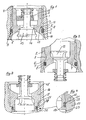
- a check valve according to the invention is described in longitudinal section with a valve housing 1, which is screwed via an external thread 2 in an internal thread 3 a bore 4 of a mounting wall 5, wherein the valve housing 1 has a portion 6, which identifies a larger diameter than the diameter of the external thread 2 and in which a circumferential groove 7 is arranged, which receives an O-ring 8.
- This O-ring 8 abuts with its outside on a fitting bore portion 9 of the bore 4, with which it cooperates for sealing.
- the bore 4 has a cone 10 from the installation side of the valve housing 1 to thereby facilitate the installation of the valve body 1 in the mounting wall 5 a relief during insertion of the O-ring 8 in the fitting bore section 9.
- a stop surface 11 is provided on the Determining the mounting position of the valve housing 1 in the bore 4 an annular surface 12 of the valve housing 1 abuts, which is formed between the external thread 2 and the outer periphery of the section 6. Stop surface 11 and annular surface 12 thus serve as a stop of the valve housing 1, when it is installed in the mounting wall 5. After installation of the valve housing 1 is thus at this point a press connection. The forces arising during assembly are taken up in particular by the annular portion of the valve housing 1, which is formed on the one hand by the radial groove wall of the groove 7 and on the other hand by the annular surface 12. Even at high pressures is prevented due to this press connection that the O-ring 8 is pushed through to the thread here.
- the actual check valve is arranged in the valve housing 1 in the form of the movable valve member 13, a common with the valve housing 1 valve seat 14 and a closing spring 15th
- Fig. 2 shown variant of this check valve, only the movable valve member 13 is arranged in the reverse opening direction with respect to the valve housing 1. All other components, in particular the structure of the valve housing 1 with its external thread 2 and the mounting wall 5 with the internal thread 3, and groove 7 and O-ring 8 in accordance with their construction in the Fig. 1 illustrated check valve. Only by the position of the O-ring 8 in the groove 7 can be seen that the high pressure comes from the other side. However, the preconditions given for the installation of the check valve are the same.
- a non-inventive example is shown, in which the installation of the valve housing 16 takes place in the mounting wall 17 from the side of the thread 18 forth. This may make it necessary to insert the round cord seal 19 and its groove 20 first, before then the thread 18 engages.
- the press fit 21, which serves as a stop, between the groove 20 and the thread 18 is arranged.
- the press fit 21 and the round cord seal 19 are located behind the thread 18.
- the sealing fit is located in a region of the valve housing that is very critical in terms of the material thickness. The reduction of the material thickness is due to the constructive necessity of serving as a stop press fit 21, which reduces the inner diameter of the fitting bore 23 and, accordingly, the diameter of the valve housing 16 in the region of its groove 20.
- the transition 22, in particular on the side of the mounting wall 17, be formed rounded to thereby easily introduce the round cord seal 19 into the fitting bore 23 of the mounting wall 17 can.
- the high pressure seal of the check valve by a press connection in the form of a separate formed as a step stop surface 11, on which an annular surface 12 of the valve housing 1, 16 after screwing the same in the mounting wall 5, 17 is realized, is used in the in Fig. 5 shown third variant, a conical inner surface 24 of a mounting wall 25 as a stop for the same slope having conical Outer surface 26 of a valve housing 27.
- a groove 28 for receiving a round cord seal 29 is incorporated into the conical outer surface 26.
- valve housing 27 between the groove 28 and its thread 30 has a recess 31, which is not provided here with a stop surface, but creates the necessary space for screwing the valve housing 27 into the mounting wall 25 so that the interference fit actually occurs between the conical surfaces 24 and 26 before the valve housing 27 reaches the thread of the mounting wall 25 with the edge formed by its conical outer surface 26.
- a high-pressure seal for a check valve with a valve housing 32 which has a spherical portion outer surface 33 in the region of the press fit abuts when screwing the valve housing 32 into the mounting wall 34 at its the same radius R as the spherical portion outer surface 33 having concavely curved inner surface 35.
- a groove 36 for receiving a round cord seal 37 is incorporated here as well.
- Fig. 7 shows a variant of the installation of two check valves in a threaded bore of a housing 38 having a radial opening 39 in which a piston 40 is guided.
- the directions of movement of the piston 40 are indicated by a double arrow, the direction of flow of the medium through the two arrows in the axis of the threaded bore.
- Such a combination can be used for example in hydraulic piston pumps.
- the reference numbers were based on examples two ( 3 and 4 ) and three ( Fig. 5 ), since these two variants are used here.
- the two valve housing 16, 27 are screwed from the same side into the housing 38, wherein the first to be screwed valve housing 16 according to the second example in Fig.
- valve housing 27 is corresponding to that in the third embodiment in Fig. 5 shown variant executed.
- the conical inner surface 42 in the housing 38 to which the conical outer surface 26 applies when screwing the valve housing 27.
- Both sealing fits are provided as in Examples two and three with a round cord seal.
Landscapes
- Engineering & Computer Science (AREA)
- General Engineering & Computer Science (AREA)
- Mechanical Engineering (AREA)
- Gasket Seals (AREA)
- Containers And Packaging Bodies Having A Special Means To Remove Contents (AREA)
- Valve Housings (AREA)
- Check Valves (AREA)
- Installation Of Indoor Wiring (AREA)
Claims (6)
- Fermeture étanche à haute pression, comprenant une paroi et de filetage,- pouvant être vissé dans un perçage de la paroi de montage comportant un filetage interne, jusqu'à ce qu'il- s'applique sur une butée déterminant la position de montage axiale de l'insert fileté, située entre l'insert fileté et la paroi de montage,- la butée étant formée par une diminution du diamètre du perçage de la paroi de montage,- un ajustement d'étanchéité (9) surfacique étant prévu dans le sens de vissage, axialement derrière le filetage (2, 30) de l'insert fileté, radialement entre un tronçon (6) du boîtier (1, 27, 32) de l'insert fileté d'une part, et un tronçon de paroi du perçage (4) de la paroi de montage (5, 25, 34) d'autre part, l'ajustement d'étanchéité (9) présentant un diamètre supérieur à celui du filetage de l'insert fileté (1) et à celui du perçage (4) recevant celui-ci,- et le diamètre du boîtier (1, 27, 32) de l'insert fileté ainsi que le diamètre du perçage (4) de la paroi de montage (5, 25, 34) diminuant dans la région de l'ajustement d'étanchéité surfacique (9) dans le sens de vissage,caractérisée en ce que
une rainure (7, 28, 36) destinée à recevoir un joint torique (8, 29, 37) est prévue dans la région de l'ajustement d'étanchéité surfacique (9) du boîtier (1, 27, 32) de l'insert fileté. - Fermeture étanche à haute pression selon la revendication 1,
caractérisé en ce que
la diminution du diamètre du boîtier (1) et du perçage (4) dans la région de l'ajustement d'étanchéité (9) est réalisée par paliers et forme donc un palier de butée (12). - Fermeture étanche à haute pression selon la revendication 1,
caractérisé en ce que
la diminution de diamètre du boîtier (27, 32) et du perçage (4) dans la région de l'ajustement d'étanchéité (9) est continue. - Fermeture étanche à haute pression selon la revendication 1,
caractérisée en ce que
la diminution de diamètre du boîtier (27, 32) et du perçage (4) dans la région de l'ajustement d'étanchéité (9) est conique. - Fermeture étanche à haute pression selon la revendication 3,
caractérisée en ce que
la diminution de diamètre du boîtier (32) et du perçage (4) de la paroi de montage (34) dans la région de l'ajustement d'étanchéité (9) est courbée et en ce que le rayon de courbure (R) présente un point central situé au niveau du point d'intersection entre l'axe du perçage (4) et la face frontale de l'insert fileté (32) qui est détournée du filetage (30). - Fermeture étanche à haute pression selon la revendication 1,
caractérisée en ce que
le perçage (10) est conçu de façon sensiblement conique (15°) en amont de l'ajustement d'étanchéité (9) et sur le côté détourné du filetage (2) par rapport à la rainure (7).
Applications Claiming Priority (2)
| Application Number | Priority Date | Filing Date | Title |
|---|---|---|---|
| DE10247839A DE10247839A1 (de) | 2002-10-14 | 2002-10-14 | Rückschlagventil für strömbare Medien |
| DE10247839 | 2002-10-14 |
Publications (3)
| Publication Number | Publication Date |
|---|---|
| EP1411283A2 EP1411283A2 (fr) | 2004-04-21 |
| EP1411283A3 EP1411283A3 (fr) | 2004-05-19 |
| EP1411283B1 true EP1411283B1 (fr) | 2008-11-19 |
Family
ID=32038650
Family Applications (1)
| Application Number | Title | Priority Date | Filing Date |
|---|---|---|---|
| EP03023068A Expired - Lifetime EP1411283B1 (fr) | 2002-10-14 | 2003-10-14 | Joint d'étanchéité pour une cartouche filletée |
Country Status (3)
| Country | Link |
|---|---|
| EP (1) | EP1411283B1 (fr) |
| AT (1) | ATE414864T1 (fr) |
| DE (2) | DE10247839A1 (fr) |
Families Citing this family (5)
| Publication number | Priority date | Publication date | Assignee | Title |
|---|---|---|---|---|
| DE502004007338D1 (de) | 2003-05-22 | 2008-07-17 | Bosch Gmbh Robert | Rückschlagventil, insbesondere für eine Hochdruckpumpe einer Kraftstoffeinspritzeinrichtung für eine Brennkraftmaschine |
| DE102007017122A1 (de) * | 2007-04-11 | 2008-12-18 | Continental Automotive Gmbh | Ventil und Pumpe mit einem solchen Ventil |
| CN104141811A (zh) * | 2014-06-18 | 2014-11-12 | 浙江诚一阀门有限公司 | 高压活塞式流量调节止回多功能阀 |
| DE102016114976A1 (de) * | 2016-03-21 | 2017-09-21 | Hilite Germany Gmbh | Rückschlagventil für ein Pleuel für eine Brennkraftmaschine mit variabler Verdichtung sowie Pleuel mit einem Rückschlagventil |
| DE102020116992A1 (de) | 2020-06-29 | 2021-12-30 | Schaeffler Technologies AG & Co. KG | Ventilvorrichtung mit einem in einer Ventilaufnahme sitzenden Ventil |
Citations (1)
| Publication number | Priority date | Publication date | Assignee | Title |
|---|---|---|---|---|
| WO1998008615A1 (fr) * | 1996-08-27 | 1998-03-05 | Abb Flexible Automation Inc. | Amelioration apportee a un collecteur et a une soupape de changeur de peintures de couleur |
Family Cites Families (8)
| Publication number | Priority date | Publication date | Assignee | Title |
|---|---|---|---|---|
| DE7038465U (de) * | 1971-02-18 | G Rost & Soehne | Eckventil mit Schmutzfanger | |
| US2830620A (en) * | 1955-05-09 | 1958-04-15 | Texas Tool & Machine Co | Valve |
| DE2449443C3 (de) * | 1974-10-17 | 1982-02-18 | Heilmeier & Weinlein Fabrik für Oel-Hydraulik GmbH & Co KG, 8000 München | Umkehrbar in eine Bohrung eines Modulblocks einsetzbares Rückschlagventil |
| US4537384A (en) * | 1984-07-17 | 1985-08-27 | Brunswick Corporation | In-line check valve having combined downstream poppet support and flow control elements |
| DE3426670A1 (de) * | 1984-07-19 | 1986-01-30 | Heilmeier & Weinlein Fabrik für Oel-Hydraulik GmbH & Co KG, 8000 München | Plaettchen-rueckschlag-ventil |
| DE4403821C2 (de) * | 1994-02-08 | 2001-05-31 | Grohe Armaturen Friedrich | Rückflußverhinderer |
| JP2001248740A (ja) * | 2000-03-07 | 2001-09-14 | Pacific Ind Co Ltd | チャージバルブ用のバルブコア |
| DE10138504B9 (de) * | 2000-06-13 | 2012-12-13 | Günter Stein | Vorfederrückschlagventil |
-
2002
- 2002-10-14 DE DE10247839A patent/DE10247839A1/de not_active Withdrawn
-
2003
- 2003-10-14 DE DE50310801T patent/DE50310801D1/de not_active Expired - Lifetime
- 2003-10-14 EP EP03023068A patent/EP1411283B1/fr not_active Expired - Lifetime
- 2003-10-14 AT AT03023068T patent/ATE414864T1/de active
Patent Citations (1)
| Publication number | Priority date | Publication date | Assignee | Title |
|---|---|---|---|---|
| WO1998008615A1 (fr) * | 1996-08-27 | 1998-03-05 | Abb Flexible Automation Inc. | Amelioration apportee a un collecteur et a une soupape de changeur de peintures de couleur |
Also Published As
| Publication number | Publication date |
|---|---|
| DE50310801D1 (de) | 2009-01-02 |
| DE10247839A1 (de) | 2004-04-22 |
| ATE414864T1 (de) | 2008-12-15 |
| EP1411283A3 (fr) | 2004-05-19 |
| EP1411283A2 (fr) | 2004-04-21 |
Similar Documents
| Publication | Publication Date | Title |
|---|---|---|
| DE102017007236B4 (de) | Drosselventil mit proportionalem Überlauf | |
| DE69719204T2 (de) | Regenventil mit lagerlos geführter spindel | |
| DE3342405C2 (de) | Absperrventil | |
| EP2011928B1 (fr) | Ensemble anti-retour | |
| DE202011051425U1 (de) | Druckminderer-Anordnung | |
| WO2002016813A1 (fr) | Soupape hydraulique | |
| DE602004006564T2 (de) | Druckregelventil | |
| EP1604136B1 (fr) | Piece rapportee a inserer dans une conduite de gaz ou de liquide | |
| EP2420712B1 (fr) | Appareil de réglage pour la commande d'un flux de fluide | |
| EP1411283A2 (fr) | Joint d'étanchéité pour une cartouche filletée | |
| EP2459912B1 (fr) | Contrôleur d'écoulement de gaz | |
| DE20320754U1 (de) | Hochdruckabdichtung für Gewindeeinsätze | |
| DE19944364A1 (de) | Einbauventil für einen Gliederheizkörper | |
| DE2449443B2 (de) | Umkehrbar in eine Bohrung eines Modulblocks einsetzbares Rückschlagventil | |
| DE102004025465A1 (de) | Durchflussmengenregler | |
| DE10132001C2 (de) | Thermostatischer Regler zur Regelung der Durchflussmenge eines Fluids | |
| DE2837977A1 (de) | Schwenkverschraubung | |
| DE10140054A1 (de) | Absperrarmatur mit einem drehbeweglichen Drossel-und Verschlußkörper | |
| DE19722562B4 (de) | Rückschlagventil | |
| DE2347578A1 (de) | Egelventil fuer einen grossen temperaturbereich | |
| EP0746713B1 (fr) | Soupape inserable | |
| EP1058797B1 (fr) | Robinet-vanne | |
| DE202022103417U1 (de) | Druckmindereranordnung mit Anschlussteil zum Anschließen an eine Rohrleitung | |
| EP3514418A1 (fr) | Cartouche de soupape pour un bloc de soupape | |
| DE2152588A1 (de) | Ventilanordnung |
Legal Events
| Date | Code | Title | Description |
|---|---|---|---|
| PUAI | Public reference made under article 153(3) epc to a published international application that has entered the european phase |
Free format text: ORIGINAL CODE: 0009012 |
|
| PUAL | Search report despatched |
Free format text: ORIGINAL CODE: 0009013 |
|
| AK | Designated contracting states |
Kind code of ref document: A2 Designated state(s): AT BE BG CH CY CZ DE DK EE ES FI FR GB GR HU IE IT LI LU MC NL PT RO SE SI SK TR |
|
| AX | Request for extension of the european patent |
Extension state: AL LT LV MK |
|
| AK | Designated contracting states |
Kind code of ref document: A3 Designated state(s): AT BE BG CH CY CZ DE DK EE ES FI FR GB GR HU IE IT LI LU MC NL PT RO SE SI SK TR |
|
| AX | Request for extension of the european patent |
Extension state: AL LT LV MK |
|
| 17P | Request for examination filed |
Effective date: 20041016 |
|
| AKX | Designation fees paid |
Designated state(s): AT CH DE IT LI |
|
| 17Q | First examination report despatched |
Effective date: 20050426 |
|
| 17Q | First examination report despatched |
Effective date: 20050426 |
|
| GRAP | Despatch of communication of intention to grant a patent |
Free format text: ORIGINAL CODE: EPIDOSNIGR1 |
|
| GRAS | Grant fee paid |
Free format text: ORIGINAL CODE: EPIDOSNIGR3 |
|
| GRAA | (expected) grant |
Free format text: ORIGINAL CODE: 0009210 |
|
| AK | Designated contracting states |
Kind code of ref document: B1 Designated state(s): AT CH DE IT LI |
|
| REG | Reference to a national code |
Ref country code: CH Ref legal event code: EP |
|
| REF | Corresponds to: |
Ref document number: 50310801 Country of ref document: DE Date of ref document: 20090102 Kind code of ref document: P |
|
| REG | Reference to a national code |
Ref country code: CH Ref legal event code: NV Representative=s name: PATENTANWAELTE SCHAAD, BALASS, MENZL & PARTNER AG |
|
| PLBE | No opposition filed within time limit |
Free format text: ORIGINAL CODE: 0009261 |
|
| STAA | Information on the status of an ep patent application or granted ep patent |
Free format text: STATUS: NO OPPOSITION FILED WITHIN TIME LIMIT |
|
| 26N | No opposition filed |
Effective date: 20090820 |
|
| PGFP | Annual fee paid to national office [announced via postgrant information from national office to epo] |
Ref country code: AT Payment date: 20101020 Year of fee payment: 8 |
|
| PGFP | Annual fee paid to national office [announced via postgrant information from national office to epo] |
Ref country code: CH Payment date: 20101025 Year of fee payment: 8 |
|
| PGFP | Annual fee paid to national office [announced via postgrant information from national office to epo] |
Ref country code: IT Payment date: 20101027 Year of fee payment: 8 |
|
| REG | Reference to a national code |
Ref country code: CH Ref legal event code: PL |
|
| PG25 | Lapsed in a contracting state [announced via postgrant information from national office to epo] |
Ref country code: LI Free format text: LAPSE BECAUSE OF NON-PAYMENT OF DUE FEES Effective date: 20111031 Ref country code: CH Free format text: LAPSE BECAUSE OF NON-PAYMENT OF DUE FEES Effective date: 20111031 |
|
| PG25 | Lapsed in a contracting state [announced via postgrant information from national office to epo] |
Ref country code: IT Free format text: LAPSE BECAUSE OF NON-PAYMENT OF DUE FEES Effective date: 20111014 |
|
| REG | Reference to a national code |
Ref country code: AT Ref legal event code: MM01 Ref document number: 414864 Country of ref document: AT Kind code of ref document: T Effective date: 20111014 |
|
| PG25 | Lapsed in a contracting state [announced via postgrant information from national office to epo] |
Ref country code: AT Free format text: LAPSE BECAUSE OF NON-PAYMENT OF DUE FEES Effective date: 20111014 |
|
| REG | Reference to a national code |
Ref country code: DE Ref legal event code: R082 Ref document number: 50310801 Country of ref document: DE Representative=s name: PATENTANWAELTE SCHUSTER, MUELLER & PARTNER MBB, DE |
|
| PGFP | Annual fee paid to national office [announced via postgrant information from national office to epo] |
Ref country code: DE Payment date: 20221004 Year of fee payment: 20 |
|
| P01 | Opt-out of the competence of the unified patent court (upc) registered |
Effective date: 20230523 |
|
| REG | Reference to a national code |
Ref country code: DE Ref legal event code: R071 Ref document number: 50310801 Country of ref document: DE |