EP1411304A1 - Abluftdiffusor und entlüftungsverfahren - Google Patents
Abluftdiffusor und entlüftungsverfahren Download PDFInfo
- Publication number
- EP1411304A1 EP1411304A1 EP20030103793 EP03103793A EP1411304A1 EP 1411304 A1 EP1411304 A1 EP 1411304A1 EP 20030103793 EP20030103793 EP 20030103793 EP 03103793 A EP03103793 A EP 03103793A EP 1411304 A1 EP1411304 A1 EP 1411304A1
- Authority
- EP
- European Patent Office
- Prior art keywords
- exhaust
- diffuser
- air
- blowing
- duct
- Prior art date
- Legal status (The legal status is an assumption and is not a legal conclusion. Google has not performed a legal analysis and makes no representation as to the accuracy of the status listed.)
- Granted
Links
Images


Classifications
-
- F—MECHANICAL ENGINEERING; LIGHTING; HEATING; WEAPONS; BLASTING
- F24—HEATING; RANGES; VENTILATING
- F24F—AIR-CONDITIONING; AIR-HUMIDIFICATION; VENTILATION; USE OF AIR CURRENTS FOR SCREENING
- F24F13/00—Details common to, or for air-conditioning, air-humidification, ventilation or use of air currents for screening
- F24F13/24—Means for preventing or suppressing noise
-
- F—MECHANICAL ENGINEERING; LIGHTING; HEATING; WEAPONS; BLASTING
- F24—HEATING; RANGES; VENTILATING
- F24F—AIR-CONDITIONING; AIR-HUMIDIFICATION; VENTILATION; USE OF AIR CURRENTS FOR SCREENING
- F24F7/00—Ventilation
- F24F7/02—Roof ventilation
-
- F—MECHANICAL ENGINEERING; LIGHTING; HEATING; WEAPONS; BLASTING
- F24—HEATING; RANGES; VENTILATING
- F24F—AIR-CONDITIONING; AIR-HUMIDIFICATION; VENTILATION; USE OF AIR CURRENTS FOR SCREENING
- F24F13/00—Details common to, or for air-conditioning, air-humidification, ventilation or use of air currents for screening
- F24F13/24—Means for preventing or suppressing noise
- F24F2013/242—Sound-absorbing material
Definitions
- the present invention relates to a diffuser for blowing off exhaust air, in which are arranged an underside intake connection for connecting the diffuser for blowing off exhaust-air to the exhaust-air duct and a topside exhaust outlet for blowing off the flow from the diffuser for blowing off exhaust-air and to which is fitted a flow duct, surrounding the casing structure, between the intake connection and the exhaust outlet.
- the invention also relates to a method for blowing off exhaust air.
- Various symmetrical diffuser elements represent the prior art in blowing off air from the ventilation systems of buildings.
- Their known round or square casing structures include an underside intake connection, from which the element is connected to a ventilation exhaust-air duct, or similar.
- a topside exhaust outlet At the opposite end of the casing structure to the intake connection there is a topside exhaust outlet, from which the exhaust air brought through the duct is blown off, for example, directly into the outer air.
- Examples relating to the prior art include the solutions disclosed in the JP publication 1290908 and DE patent 100 31 083 C1.
- the operation of the diffuser is based roughly on two expansion chambers (A, B), between which the flow is throttled by a baffle element.
- the route of the flow through the diffuser forms a zig-zag pattern.
- the pressure drop will become quite considerable, thus weakening its operational capacity in practical implementations.
- the invention in the DE publication related to effective water removal from a diffuser.
- symmetrical structures and also asymmetrical, highly simplified constructions are disclosed.
- the asymmetricality is achieved by forming a bend that diverts vertically the flow in the duct.
- the use of only a pipe bend of this kind will not achieve any kind of effective diffuser, which will instead also show the drawbacks described below that relate to exhaust-air diffusers in general.
- One first such drawback is the tendency of exhaust-air diffusers to ice in sub-zero air.
- the humidity of the condensing indoor air which is warmer that the outdoor temperature, causes problems in the operation of the diffuser, in the form of wetting and also icing, due precisely to known diffuser structures having water-collection and removal members that may operate poorly, or which may be even entirely lacking.
- a second significant drawback is the aforementioned lack of noise attenuation by the diffuser structures.
- the amplification of low frequencies is passed a general problem in diffusers.
- the effective attenuation of low frequencies would require an unreasonably large size of separate silencer element, which would correspondingly increase the manufacturing and material costs of the silencer, besides also being aesthetically detrimental on roofs.
- the present invention is intended to create a diffuser for blowing off exhaust air and a method in blowing off exhaust air that are, in all respects, better and more effect than previously.
- the characteristic features of the diffuser for blowing off exhaust air according to the invention are stated in the accompanying Claim 1 while the characteristic features of the method are stated in Claim 10.
- the diffuser for blowing off exhaust air according to the invention is surprisingly formed as an asymmetrical structure, with an integrated diffuser function for blowing off exhaust air, and an integrated attenuation function for noise arising in the exhaust air ducts and in diffuser.
- the attenuation is achieved with the aid of a smooth diversion of the airflow, arranged in the flow duct of the diffuser, and of an attenuation material arranged in connection with the flow duct.
- the direction of the airflow being blown off is, according to the method of the invention, diverted horizontally, when viewing the diffuser from the side, thus simultaneously achieving, among other things, effective attenuation properties and improved moisture resistance and removal.
- the diversion is created by means of the surprising asymmetrical flow duct construction of the internal components of the diffuser, in which the exhaust outlet has a different vertical alignment to that of the intake connection.
- the diffuser 10 for blowing off waste or exhaust air is suitable for use in several different applications in the ventilation systems of buildings.
- the diffuser 10 can be easily connected to exhaust ducts 22 of different models and shapes.
- the diffuser 10 is examined, by way of example, with reference to the accompanying Figures 1 - 4, in connection with blowing off exhaust air.
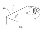
- Figure 1 shows the diffuser 10, according to the invention, at its point of use.
- An exhaust air (arrows) blow-off duct 22 has been installed in the building 20 and taken through the roof 21.
- the exhaust air can be blown off mechanically, impelled by a fan.
- the diffuser 10 according to the invention can be used in so-called low-pressure-drop blowing off.
- the blow-off volumes can be, for example, 1 - 10 m 3 /s, and even 15 m 3 /s.
- the diffuser 10, with, according to the invention, a diffuser function and sound attenuation function integrated in the same casing structure 11, is connected to the upper end of the duct 22.
- the integrated diffuser 10 As is known, very little space is allocated in the interior of the building 20 for the ventilation ducts runs and the operational elements located in connection with them, such as, for example, sound attenuator.
- the use of the integrated diffuser 10 according to the invention not only achieves significant space savings in buildings, but also improves the serviceability of the ventilation. In applications above roof structures 21 requiring attenuation, the diffuser 10 is also considerably lower than known solutions requiring attenuation.
- FIG. 2 - 4 shows one example of a diffuser 10.
- the diffuser 10 is divided in principle into two spaces 14, 15, adjacent to each other horizontally, forming an asymmetrical structure.
- the figures show a space 15 in the right-hand side half of the diffuser's casing structure 11, to which the airflow shown with the broken arrow is led from the exhaust duct 22, through the intake connection 12 beneath the casing structure 11.
- the space 15 can also be termed the attenuation chamber and in shape it corresponds at least to the lower part of the casing structure 11 as an upright segmented semi-cylinder 26.1 (U-section), which, in Figure 2, opens to the left.
- a space 14 On the left of the attenuation chamber 15 is a space 14, the upper part of which has an exhaust outlet 13, from which the flow, shown by a broken arrow, is led out of the diffuser 10, for example, to the outdoor air.
- This space can also be termed the exhaust-air passage 14, which in shape corresponds to a slightly flattened rectangular prism.
- the height of the passage 14 can correspond substantially to the height of the casing structure 11.
- the intake connection 12 and the exhaust outlet 13 have at least partly different vertical alignments.
- the spaces 14 and 15 together form a flow duct surrounding the casing structure 11.
- the flow duct 14, 15 can preferably be a single-passage structure.
- a support plate 31 ( Figure 2), which reinforces the structure of the diffuser 10.
- the support plate 31 cannot, however, be regarded as having any functional effect on the operation of the diffuser 10, because it can also be omitted, if the diffuser 10 is made from thicker material.
- the direction of the airflow led from the attenuation chamber 15 of the diffuser 10 to the exhaust-air passage 14 is diverted smoothly in the asymmetrically arranged flow duct 14, 15 of the diffuser 10.
- the diversion takes place horizontally, when examined from the side of the diffuser 10.
- the diversion, and the attenuation of noise achieved with its aid are achieved by means of one or more baffles in the attenuation chamber 15, arranged in connection with the attenuation material 28.1, 28.2, one example of which is the baffle plate 17 shown.
- the air baffle 17 that creates the smooth, asymmetrical flow is positioned in the casing structure 11 in such a way that its lower edge, i.e. the one on the right-hand side in Figure 4 is relative to the exhaust-air passage 14 in the opposite edge of the casing structure 11, close to the intake connection 12. From there, the air baffle 17 slopes upwards towards the exhaust-air passage 14 and guides the flow, which is led from the intake connection 12 to the diffuser 10, towards the exhaust outlet 13. When the air baffle 17 reaches the exhaust-air passage 14, it is vertically at a level slightly above the middle of the casing structure 11. At this point, there is a bend in the air baffle 17, from which it continues upwards as a vertical wall structure 25, to nearly the top of the diffuser 10. Over this vertical part, the air baffle 17 forms a wall 25 of the upper part of the exhaust-air passage 14, with the entire length of the opposite wall being formed by the casing structure 11.
- the support plate 31 can be between the wall 25 and the casing structure 11.
- baffle 17 Due to the slightly flattened shape of the casing structure 11, small flanges 24 are bent into the edges of the air-baffle 17 that rise from the attenuation chamber 15 towards the exhaust-air passage 14.
- the baffle 17 is attached securely to the casing structure 11 by the flanges 24 and also supports an insulation layer 28.1 that extends in the upper space 30 to the level of the cover 18.
- the exhaust-air passage 14 and the attenuation chamber 15 forming the flow duct are thus connected to each other, from the intake connection 12 of the lower part of the casing structure 11, to slightly above the vertical level of the middle of the casing structure 11.
- the base 23 of the casing structure 11, to which the intake connection 12 is also fitted, is in the lower part of the exhaust-air passage 14.
- the intake connection 12 has a small collar 16.2 on the inside of the casing structure 11, which is used to prevent water that collects on the base from entering the duct 22 through the intake connection 12.
- the lower circumference 19 of the casing structure 11 is formed of pressed support sheet-metal, with reinforcing grooves in it.
- the casing structure 11 can be assembled, for example from two segments, one half of which is shown in Figure 4.
- the semi-cylindrical space 26 for the sound-insulating layer 28.2 is arranged in the attenuation chamber 15, partly surrounding coaxially an imaginary continuation of the intake connection 12. On its internal circumference, the space 26 is bounded, by a U-section plate 26.1, which opens to the exhaust-air passage 14, and which preferably has perforations 29.2, at least in the area corresponding to the attenuation space 15.
- the perforations 29.1 which also cover the entire air baffle 17, cover 20 - 40 %, preferably 25 - 35 % of the surface area of the plate 17, 26.1.
- the outer wall 26.2 of the insulation space 26 is a blank U-section that also opens towards the exhaust-air passage 14 and is also of sheet-metal material, like the inner wall 26.1. Further, a narrow passage 27, which can be used for water-removal purposes, remains between the outer wall 26.2 that limits the insulation space 26 and the outer jacket of the casing structure 11 of the diffuser 10.
- the base 23 of the casing structure 11 can also slope slightly, in which case its lowest point will have an outlet (not shown) for water that may have collected inside it.
- the cover 18 In the upper part of the attenuation chamber 15, there is a cover 18 on top of the insulation spaces 26, 30, which slopes away from the exhaust-air passage 14.
- the cover 18 has a visor 18.1 that protrudes for a distance over the exhaust-air passage 14.
- the cover 18 On the side opposite to the visor 18.1, the cover 18 extends at least to the water-removal passage 27, to which water raining or melting on the cover 18 can flow.
- the essential feature of the cover 18, is that it covers the insulation 28.1, 28.2, which is thus not only in the semi-cylindrical insulation space 26, but also in the space 30 above the baffle 17, at least as far as the cover 18. Pilot-stage tests of the diffuser 10 have shown the insulation 28.1 arranged in the space 30 to be more important than, for example, the insulation 28.2 arranged in the space 26.
- the insulation material 28.1, 28.2 placed in the insulation space 26 and in the space 30 remaining between the baffle plate 17 and the cover 18 can be of a grade suitable for sound insulation.
- One such material is Dacron wadding.
- the insulation 28.1, 28.2 also functions as thermal insulation, which helps to improve the operation of the diffuser 10 in cold conditions.
- Yet another advantageous property of the attenuation material 28.1, 28.2 is that it does not absorb moisture.
- the attenuation material itself can form the baffle surface that diverts the airflow.
- the attenuation material itself can form the baffle surface that diverts the airflow.
- the sheet-metal components 11, 17, 19, 23, 26.1, 26.2 of the diffuser 10 can be, for example, FeZn sheet, which can be painted in several different colours. Further, combinations of different colours are possible in the casing structure 11, as the lower circumference 19 can be painted a different colour to the upper part, as can the halves of the cross-section of the casing structure 11. Otherwise, the diffuser 10 is a harmonious entity as architectural.
- the integrated attenuation function of the diffuser 10 according to the invention reduces the costs associated with the ventilation of buildings and meets environmental statutory noise-attenuation requirements. Now the diffuser 10 can also be cleaned more easily than before.
Landscapes
- Engineering & Computer Science (AREA)
- Chemical & Material Sciences (AREA)
- Combustion & Propulsion (AREA)
- Mechanical Engineering (AREA)
- General Engineering & Computer Science (AREA)
- Duct Arrangements (AREA)
- Golf Clubs (AREA)
- Telephone Function (AREA)
- External Artificial Organs (AREA)
- Percussion Or Vibration Massage (AREA)
- Exhaust Silencers (AREA)
- Pipe Accessories (AREA)
Applications Claiming Priority (2)
| Application Number | Priority Date | Filing Date | Title |
|---|---|---|---|
| FI20025047A FI20025047A7 (fi) | 2002-10-18 | 2002-10-18 | Ulospuhallushajoittaja ja menetelmä ilman ulospuhalluksessa |
| FI20025047 | 2002-10-18 |
Publications (2)
| Publication Number | Publication Date |
|---|---|
| EP1411304A1 true EP1411304A1 (de) | 2004-04-21 |
| EP1411304B1 EP1411304B1 (de) | 2007-02-28 |
Family
ID=8565216
Family Applications (1)
| Application Number | Title | Priority Date | Filing Date |
|---|---|---|---|
| EP03103793A Expired - Lifetime EP1411304B1 (de) | 2002-10-18 | 2003-10-14 | Abluftdiffusor und entlüftungsverfahren |
Country Status (4)
| Country | Link |
|---|---|
| EP (1) | EP1411304B1 (de) |
| AT (1) | ATE355494T1 (de) |
| DE (1) | DE60312098D1 (de) |
| FI (1) | FI20025047A7 (de) |
Cited By (1)
| Publication number | Priority date | Publication date | Assignee | Title |
|---|---|---|---|---|
| BE1017133A3 (nl) * | 2005-05-11 | 2008-03-04 | Renson Paul | Ventilatie-inrichting. |
Citations (5)
| Publication number | Priority date | Publication date | Assignee | Title |
|---|---|---|---|---|
| US3125286A (en) * | 1964-03-17 | sanders | ||
| JPH01290908A (ja) * | 1988-05-16 | 1989-11-22 | Tsutomu Tajima | 消音装置 |
| DE4410437A1 (de) * | 1993-09-10 | 1995-03-16 | Karl Heinz Vahlbrauk | Fertigschornstein |
| JP2000111111A (ja) * | 1998-10-05 | 2000-04-18 | Mitsubishi Electric Corp | フード |
| US20020125068A1 (en) * | 2001-03-06 | 2002-09-12 | Twin City Fan Companies , Ltd. | Weatherproof sound attenuating device |
-
2002
- 2002-10-18 FI FI20025047A patent/FI20025047A7/fi not_active Application Discontinuation
-
2003
- 2003-10-14 EP EP03103793A patent/EP1411304B1/de not_active Expired - Lifetime
- 2003-10-14 AT AT03103793T patent/ATE355494T1/de not_active IP Right Cessation
- 2003-10-14 DE DE60312098T patent/DE60312098D1/de not_active Expired - Lifetime
Patent Citations (5)
| Publication number | Priority date | Publication date | Assignee | Title |
|---|---|---|---|---|
| US3125286A (en) * | 1964-03-17 | sanders | ||
| JPH01290908A (ja) * | 1988-05-16 | 1989-11-22 | Tsutomu Tajima | 消音装置 |
| DE4410437A1 (de) * | 1993-09-10 | 1995-03-16 | Karl Heinz Vahlbrauk | Fertigschornstein |
| JP2000111111A (ja) * | 1998-10-05 | 2000-04-18 | Mitsubishi Electric Corp | フード |
| US20020125068A1 (en) * | 2001-03-06 | 2002-09-12 | Twin City Fan Companies , Ltd. | Weatherproof sound attenuating device |
Non-Patent Citations (2)
| Title |
|---|
| PATENT ABSTRACTS OF JAPAN vol. 014, no. 071 (M - 0933) 9 February 1990 (1990-02-09) * |
| PATENT ABSTRACTS OF JAPAN vol. 2000, no. 07 29 September 2000 (2000-09-29) * |
Cited By (1)
| Publication number | Priority date | Publication date | Assignee | Title |
|---|---|---|---|---|
| BE1017133A3 (nl) * | 2005-05-11 | 2008-03-04 | Renson Paul | Ventilatie-inrichting. |
Also Published As
| Publication number | Publication date |
|---|---|
| FI20025047A7 (fi) | 2004-04-19 |
| ATE355494T1 (de) | 2006-03-15 |
| EP1411304B1 (de) | 2007-02-28 |
| DE60312098D1 (de) | 2007-04-12 |
| FI20025047A0 (fi) | 2002-10-18 |
Similar Documents
| Publication | Publication Date | Title |
|---|---|---|
| CA2363895C (en) | Air inlet and outlet silencer structures for turbine | |
| EP1326054B1 (de) | Dekorative platte für klimaanlage, ablasseinheit für luftauslass und klimaanlage | |
| CN101676638B (zh) | 吸顶式空调机 | |
| EP1890087A1 (de) | Klimaanlage mit Luftleitelement zur Geräuschreduzierung | |
| US8210308B2 (en) | Sound attentuator | |
| CA2155789C (en) | Acoustic attenuating curb | |
| US7392821B2 (en) | Drain water discharge structure for air conditioner | |
| EP1411304B1 (de) | Abluftdiffusor und entlüftungsverfahren | |
| KR100699398B1 (ko) | 천장 현수형 공기 조화 장치 | |
| CN211926103U (zh) | 一种冷凝水引流装置及空调器 | |
| KR100937309B1 (ko) | 증발기 유닛용 응축물 배수 팬 | |
| JP7770959B2 (ja) | 屋外フード | |
| JP3214599B2 (ja) | 空気調和機 | |
| KR100816525B1 (ko) | 배기용 후드 | |
| JP3067444B2 (ja) | 天井埋込型空気調和機 | |
| JP2000065376A (ja) | 天井カセット形空気調和機 | |
| JP5446220B2 (ja) | 送風装置 | |
| CN114909718A (zh) | 除湿结构、新风管组件和新风空调 | |
| JP4659101B2 (ja) | 換気機能付き空気調和機 | |
| JP4298470B2 (ja) | 換気機能付き空気調和機 | |
| KR102815336B1 (ko) | 드레인 커버를 포함하는 공조 장치 | |
| KR20050064963A (ko) | 덕트형 공기조화기의 배관 지지구조 | |
| CN2424408Y (zh) | 顶置式空调装置 | |
| US20250102183A1 (en) | Air handling unit comprising drain cover | |
| KR100188399B1 (ko) | 공기조화기의 열교환기 |
Legal Events
| Date | Code | Title | Description |
|---|---|---|---|
| PUAI | Public reference made under article 153(3) epc to a published international application that has entered the european phase |
Free format text: ORIGINAL CODE: 0009012 |
|
| AK | Designated contracting states |
Kind code of ref document: A1 Designated state(s): AT BE BG CH CY CZ DE DK EE ES FI FR GB GR HU IE IT LI LU MC NL PT RO SE SI SK TR |
|
| AX | Request for extension of the european patent |
Extension state: AL LT LV MK |
|
| 17P | Request for examination filed |
Effective date: 20041011 |
|
| AKX | Designation fees paid |
Designated state(s): AT BE BG CH CY CZ DE DK EE ES FI FR GB GR HU IE IT LI LU MC NL PT RO SE SI SK TR |
|
| AXX | Extension fees paid |
Extension state: LV Payment date: 20041011 Extension state: LT Payment date: 20041011 |
|
| GRAP | Despatch of communication of intention to grant a patent |
Free format text: ORIGINAL CODE: EPIDOSNIGR1 |
|
| GRAS | Grant fee paid |
Free format text: ORIGINAL CODE: EPIDOSNIGR3 |
|
| GRAA | (expected) grant |
Free format text: ORIGINAL CODE: 0009210 |
|
| AK | Designated contracting states |
Kind code of ref document: B1 Designated state(s): AT BE BG CH CY CZ DE DK EE ES FI FR GB GR HU IE IT LI LU MC NL PT RO SE SI SK TR |
|
| AX | Request for extension of the european patent |
Extension state: LT LV |
|
| PG25 | Lapsed in a contracting state [announced via postgrant information from national office to epo] |
Ref country code: LI Free format text: LAPSE BECAUSE OF FAILURE TO SUBMIT A TRANSLATION OF THE DESCRIPTION OR TO PAY THE FEE WITHIN THE PRESCRIBED TIME-LIMIT Effective date: 20070228 Ref country code: SI Free format text: LAPSE BECAUSE OF FAILURE TO SUBMIT A TRANSLATION OF THE DESCRIPTION OR TO PAY THE FEE WITHIN THE PRESCRIBED TIME-LIMIT Effective date: 20070228 Ref country code: CH Free format text: LAPSE BECAUSE OF FAILURE TO SUBMIT A TRANSLATION OF THE DESCRIPTION OR TO PAY THE FEE WITHIN THE PRESCRIBED TIME-LIMIT Effective date: 20070228 Ref country code: NL Free format text: LAPSE BECAUSE OF FAILURE TO SUBMIT A TRANSLATION OF THE DESCRIPTION OR TO PAY THE FEE WITHIN THE PRESCRIBED TIME-LIMIT Effective date: 20070228 Ref country code: BE Free format text: LAPSE BECAUSE OF FAILURE TO SUBMIT A TRANSLATION OF THE DESCRIPTION OR TO PAY THE FEE WITHIN THE PRESCRIBED TIME-LIMIT Effective date: 20070228 Ref country code: DK Free format text: LAPSE BECAUSE OF FAILURE TO SUBMIT A TRANSLATION OF THE DESCRIPTION OR TO PAY THE FEE WITHIN THE PRESCRIBED TIME-LIMIT Effective date: 20070228 Ref country code: AT Free format text: LAPSE BECAUSE OF FAILURE TO SUBMIT A TRANSLATION OF THE DESCRIPTION OR TO PAY THE FEE WITHIN THE PRESCRIBED TIME-LIMIT Effective date: 20070228 |
|
| REG | Reference to a national code |
Ref country code: GB Ref legal event code: FG4D |
|
| REG | Reference to a national code |
Ref country code: CH Ref legal event code: EP |
|
| REF | Corresponds to: |
Ref document number: 60312098 Country of ref document: DE Date of ref document: 20070412 Kind code of ref document: P |
|
| REG | Reference to a national code |
Ref country code: IE Ref legal event code: FG4D |
|
| PG25 | Lapsed in a contracting state [announced via postgrant information from national office to epo] |
Ref country code: BG Free format text: LAPSE BECAUSE OF EXPIRATION OF PROTECTION Effective date: 20070529 |
|
| REG | Reference to a national code |
Ref country code: SE Ref legal event code: TRGR |
|
| PG25 | Lapsed in a contracting state [announced via postgrant information from national office to epo] |
Ref country code: ES Free format text: LAPSE BECAUSE OF FAILURE TO SUBMIT A TRANSLATION OF THE DESCRIPTION OR TO PAY THE FEE WITHIN THE PRESCRIBED TIME-LIMIT Effective date: 20070608 |
|
| PG25 | Lapsed in a contracting state [announced via postgrant information from national office to epo] |
Ref country code: PT Free format text: LAPSE BECAUSE OF FAILURE TO SUBMIT A TRANSLATION OF THE DESCRIPTION OR TO PAY THE FEE WITHIN THE PRESCRIBED TIME-LIMIT Effective date: 20070730 |
|
| NLV1 | Nl: lapsed or annulled due to failure to fulfill the requirements of art. 29p and 29m of the patents act | ||
| LTIE | Lt: invalidation of european patent or patent extension |
Effective date: 20070228 |
|
| REG | Reference to a national code |
Ref country code: CH Ref legal event code: PL |
|
| EN | Fr: translation not filed | ||
| PG25 | Lapsed in a contracting state [announced via postgrant information from national office to epo] |
Ref country code: SK Free format text: LAPSE BECAUSE OF FAILURE TO SUBMIT A TRANSLATION OF THE DESCRIPTION OR TO PAY THE FEE WITHIN THE PRESCRIBED TIME-LIMIT Effective date: 20070228 |
|
| PG25 | Lapsed in a contracting state [announced via postgrant information from national office to epo] |
Ref country code: RO Free format text: LAPSE BECAUSE OF FAILURE TO SUBMIT A TRANSLATION OF THE DESCRIPTION OR TO PAY THE FEE WITHIN THE PRESCRIBED TIME-LIMIT Effective date: 20070228 Ref country code: CZ Free format text: LAPSE BECAUSE OF FAILURE TO SUBMIT A TRANSLATION OF THE DESCRIPTION OR TO PAY THE FEE WITHIN THE PRESCRIBED TIME-LIMIT Effective date: 20070228 |
|
| PLBE | No opposition filed within time limit |
Free format text: ORIGINAL CODE: 0009261 |
|
| STAA | Information on the status of an ep patent application or granted ep patent |
Free format text: STATUS: NO OPPOSITION FILED WITHIN TIME LIMIT |
|
| PG25 | Lapsed in a contracting state [announced via postgrant information from national office to epo] |
Ref country code: DE Free format text: LAPSE BECAUSE OF FAILURE TO SUBMIT A TRANSLATION OF THE DESCRIPTION OR TO PAY THE FEE WITHIN THE PRESCRIBED TIME-LIMIT Effective date: 20070530 |
|
| 26N | No opposition filed |
Effective date: 20071129 |
|
| PG25 | Lapsed in a contracting state [announced via postgrant information from national office to epo] |
Ref country code: IT Free format text: LAPSE BECAUSE OF FAILURE TO SUBMIT A TRANSLATION OF THE DESCRIPTION OR TO PAY THE FEE WITHIN THE PRESCRIBED TIME-LIMIT Effective date: 20070228 Ref country code: FR Free format text: LAPSE BECAUSE OF FAILURE TO SUBMIT A TRANSLATION OF THE DESCRIPTION OR TO PAY THE FEE WITHIN THE PRESCRIBED TIME-LIMIT Effective date: 20071019 Ref country code: GR Free format text: LAPSE BECAUSE OF FAILURE TO SUBMIT A TRANSLATION OF THE DESCRIPTION OR TO PAY THE FEE WITHIN THE PRESCRIBED TIME-LIMIT Effective date: 20070529 |
|
| PG25 | Lapsed in a contracting state [announced via postgrant information from national office to epo] |
Ref country code: MC Free format text: LAPSE BECAUSE OF NON-PAYMENT OF DUE FEES Effective date: 20071031 |
|
| GBPC | Gb: european patent ceased through non-payment of renewal fee |
Effective date: 20071014 |
|
| PG25 | Lapsed in a contracting state [announced via postgrant information from national office to epo] |
Ref country code: IE Free format text: LAPSE BECAUSE OF NON-PAYMENT OF DUE FEES Effective date: 20071015 |
|
| PG25 | Lapsed in a contracting state [announced via postgrant information from national office to epo] |
Ref country code: FR Free format text: LAPSE BECAUSE OF FAILURE TO SUBMIT A TRANSLATION OF THE DESCRIPTION OR TO PAY THE FEE WITHIN THE PRESCRIBED TIME-LIMIT Effective date: 20070228 Ref country code: GB Free format text: LAPSE BECAUSE OF NON-PAYMENT OF DUE FEES Effective date: 20071014 |
|
| PG25 | Lapsed in a contracting state [announced via postgrant information from national office to epo] |
Ref country code: CY Free format text: LAPSE BECAUSE OF FAILURE TO SUBMIT A TRANSLATION OF THE DESCRIPTION OR TO PAY THE FEE WITHIN THE PRESCRIBED TIME-LIMIT Effective date: 20070228 |
|
| PG25 | Lapsed in a contracting state [announced via postgrant information from national office to epo] |
Ref country code: LU Free format text: LAPSE BECAUSE OF NON-PAYMENT OF DUE FEES Effective date: 20071014 |
|
| PG25 | Lapsed in a contracting state [announced via postgrant information from national office to epo] |
Ref country code: HU Free format text: LAPSE BECAUSE OF FAILURE TO SUBMIT A TRANSLATION OF THE DESCRIPTION OR TO PAY THE FEE WITHIN THE PRESCRIBED TIME-LIMIT Effective date: 20070901 Ref country code: TR Free format text: LAPSE BECAUSE OF FAILURE TO SUBMIT A TRANSLATION OF THE DESCRIPTION OR TO PAY THE FEE WITHIN THE PRESCRIBED TIME-LIMIT Effective date: 20070228 |
|
| PGFP | Annual fee paid to national office [announced via postgrant information from national office to epo] |
Ref country code: SE Payment date: 20220912 Year of fee payment: 20 Ref country code: EE Payment date: 20220905 Year of fee payment: 20 |
|
| PGFP | Annual fee paid to national office [announced via postgrant information from national office to epo] |
Ref country code: FI Payment date: 20221011 Year of fee payment: 20 |
|
| P01 | Opt-out of the competence of the unified patent court (upc) registered |
Effective date: 20230530 |
|
| REG | Reference to a national code |
Ref country code: SE Ref legal event code: EUG |