EP1411397B1 - Méthode et dispositif pour chauffage d'un support d'enregistrement et/ou de toner - Google Patents
Méthode et dispositif pour chauffage d'un support d'enregistrement et/ou de toner Download PDFInfo
- Publication number
- EP1411397B1 EP1411397B1 EP03018071A EP03018071A EP1411397B1 EP 1411397 B1 EP1411397 B1 EP 1411397B1 EP 03018071 A EP03018071 A EP 03018071A EP 03018071 A EP03018071 A EP 03018071A EP 1411397 B1 EP1411397 B1 EP 1411397B1
- Authority
- EP
- European Patent Office
- Prior art keywords
- resonator
- power distribution
- gap
- printing material
- microwave
- Prior art date
- Legal status (The legal status is an assumption and is not a legal conclusion. Google has not performed a legal analysis and makes no representation as to the accuracy of the status listed.)
- Expired - Lifetime
Links
- 238000000034 method Methods 0.000 title claims description 24
- 238000010438 heat treatment Methods 0.000 title claims description 13
- 238000009826 distribution Methods 0.000 claims description 51
- 239000000463 material Substances 0.000 claims description 43
- 230000029305 taxis Effects 0.000 claims 1
- 239000000758 substrate Substances 0.000 description 17
- 230000008859 change Effects 0.000 description 9
- 238000005192 partition Methods 0.000 description 7
- 230000008569 process Effects 0.000 description 7
- 238000011161 development Methods 0.000 description 6
- 230000018109 developmental process Effects 0.000 description 6
- 238000001816 cooling Methods 0.000 description 4
- 230000005684 electric field Effects 0.000 description 4
- 230000003993 interaction Effects 0.000 description 4
- 230000015572 biosynthetic process Effects 0.000 description 3
- 238000005755 formation reaction Methods 0.000 description 3
- 229920001343 polytetrafluoroethylene Polymers 0.000 description 3
- 239000004810 polytetrafluoroethylene Substances 0.000 description 3
- 230000006978 adaptation Effects 0.000 description 2
- 230000008901 benefit Effects 0.000 description 2
- 238000005520 cutting process Methods 0.000 description 2
- 230000002411 adverse Effects 0.000 description 1
- 230000008878 coupling Effects 0.000 description 1
- 238000010168 coupling process Methods 0.000 description 1
- 238000005859 coupling reaction Methods 0.000 description 1
- 230000001419 dependent effect Effects 0.000 description 1
- 238000010586 diagram Methods 0.000 description 1
- 230000000694 effects Effects 0.000 description 1
- 230000009477 glass transition Effects 0.000 description 1
- 230000006698 induction Effects 0.000 description 1
- 239000002184 metal Substances 0.000 description 1
- 238000005457 optimization Methods 0.000 description 1
- 230000005855 radiation Effects 0.000 description 1
- 230000009467 reduction Effects 0.000 description 1
- 230000007480 spreading Effects 0.000 description 1
- 238000003892 spreading Methods 0.000 description 1
Images


Classifications
-
- H—ELECTRICITY
- H05—ELECTRIC TECHNIQUES NOT OTHERWISE PROVIDED FOR
- H05B—ELECTRIC HEATING; ELECTRIC LIGHT SOURCES NOT OTHERWISE PROVIDED FOR; CIRCUIT ARRANGEMENTS FOR ELECTRIC LIGHT SOURCES, IN GENERAL
- H05B6/00—Heating by electric, magnetic or electromagnetic fields
- H05B6/64—Heating using microwaves
- H05B6/6402—Aspects relating to the microwave cavity
-
- G—PHYSICS
- G03—PHOTOGRAPHY; CINEMATOGRAPHY; ANALOGOUS TECHNIQUES USING WAVES OTHER THAN OPTICAL WAVES; ELECTROGRAPHY; HOLOGRAPHY
- G03G—ELECTROGRAPHY; ELECTROPHOTOGRAPHY; MAGNETOGRAPHY
- G03G15/00—Apparatus for electrographic processes using a charge pattern
- G03G15/20—Apparatus for electrographic processes using a charge pattern for fixing, e.g. by using heat
- G03G15/2003—Apparatus for electrographic processes using a charge pattern for fixing, e.g. by using heat using heat
- G03G15/2007—Apparatus for electrographic processes using a charge pattern for fixing, e.g. by using heat using heat using radiant heat, e.g. infrared lamps, microwave heaters
-
- H—ELECTRICITY
- H05—ELECTRIC TECHNIQUES NOT OTHERWISE PROVIDED FOR
- H05B—ELECTRIC HEATING; ELECTRIC LIGHT SOURCES NOT OTHERWISE PROVIDED FOR; CIRCUIT ARRANGEMENTS FOR ELECTRIC LIGHT SOURCES, IN GENERAL
- H05B6/00—Heating by electric, magnetic or electromagnetic fields
- H05B6/64—Heating using microwaves
- H05B6/70—Feed lines
- H05B6/705—Feed lines using microwave tuning
-
- H—ELECTRICITY
- H05—ELECTRIC TECHNIQUES NOT OTHERWISE PROVIDED FOR
- H05B—ELECTRIC HEATING; ELECTRIC LIGHT SOURCES NOT OTHERWISE PROVIDED FOR; CIRCUIT ARRANGEMENTS FOR ELECTRIC LIGHT SOURCES, IN GENERAL
- H05B6/00—Heating by electric, magnetic or electromagnetic fields
- H05B6/64—Heating using microwaves
- H05B6/80—Apparatus for specific applications
- H05B6/802—Apparatus for specific applications for heating fluids
-
- H—ELECTRICITY
- H05—ELECTRIC TECHNIQUES NOT OTHERWISE PROVIDED FOR
- H05B—ELECTRIC HEATING; ELECTRIC LIGHT SOURCES NOT OTHERWISE PROVIDED FOR; CIRCUIT ARRANGEMENTS FOR ELECTRIC LIGHT SOURCES, IN GENERAL
- H05B2206/00—Aspects relating to heating by electric, magnetic, or electromagnetic fields covered by group H05B6/00
- H05B2206/04—Heating using microwaves
- H05B2206/046—Microwave drying of wood, ink, food, ceramic, sintering of ceramic, clothes, hair
Definitions
- the invention relates to a method for heating printed material and / or toner, in particular in an electrophotographically operating printing press, with at least one standing with at least one Hohlhuntresonator standing microwave, the printing material is passed through a gap of the resonator.
- the invention relates to a device for heating printed material and / or toner, in particular in an electrophotographic printing machine, which comprises at least one resonator with at least one hollow chamber for emitted from a microwave transmitter, a microwave source or a microwave generator microwaves, the at least one standing microwave generated and has a gap through which the substrate is passed.
- a method and a device of the aforementioned type is known from DE-A-101 45 005 known.
- the intensity profile of the electric field E x which runs parallel to the width of the substrate extension, trapezoidal and almost rectangular desired. This can also be regarded as the power curve of the resonator in the corresponding x direction.
- a cooling device is arranged in the region of the resonator, which cools down the printing material so far that the temperature of the toner is below its glass transition temperature.
- the cooling device can adversely affect the heating behavior of the toner-betikruck fürs just in the overlapping region of resonators by their design. If, for example, cooling air is blown into the overlap area and the printing material is strongly cooled in this area, then the fixing result can change in this area. Also with regard to this, the overlap region can be made less sensitive to influence by the edge courses of the field strength profiles of the resonators.
- the invention has for its object to further improve a method and an apparatus of the type mentioned in relation to the above-described aspects.
- the power profile of the selected resonator for the particular requirement is designed, so to speak, specifically and individually with advantage. Due to this formability, a greater independence from the remaining arbitrariness is achieved in a selection of a resonator, in particular also with regard to the possibility according to the invention of a certain standardization of the resonators of a formation of resonators for a fixing device. It is therefore unnecessary to provide a larger assortment of resonators with checked, different sheverlaufs characteriska and a selection of suitable for the present need resonator from this range.
- the power curve is thoughtfully decomposed into characteristic areas and parameterized in some way, these areas or parameters preferably certain parameters of the resonator, which are developed and provided in preferred developments and embodiments of a resonator according to the invention, are associated with influencing the performance curve. This will be explained in more detail below in connection with the features of the claims and explained.
- the power distribution should preferably be set or changed as a function of the location, preferably primarily across the width transversely to the direction of the printing material guide.
- the power distribution as a function of the location can be divided into three main areas.
- the three areas to be distinguished are the two areas which have a continuous, almost linearly increasing power distribution (flanks) between the wall and the center, between which there is a third area with a power distribution which can be described as a curved curve.
- This curvature of the curve can be positive, negative or very small.
- this curve is referred to as a trapezoidal shape. It may preferably be provided that the slope of the flanks of this U-shape is adjusted or changed.
- the power distribution as a function of the location is set asymmetrically. This would be even more suitable, if necessary, to achieve a homogeneous heating only and only by an interaction of several resonators, as by simply flatter edge courses of the field strength profile.
- a development of the method according to the invention provides that at least one geometric size of the resonator is adjusted or changed, at least relative to at least one other geometric size of the resonator.
- a resonator according to the invention is therefore preferably parameterized via its geometrical conditions, for which purpose such suitable geometric conditions are proposed in an inventive manner and assigned to the regions of this course in order to influence the power profile profile.
- a simple solution according to the invention already consists in changing the width of the resonator gaps, that is to say the clear height through which the printing material is guided, in order to change and adjust in particular the edge steepness of the power curve.
- a device according to the invention of the type mentioned above is characterized by the features of claim 11 in an independent solution of the problem.
- the power distribution is preset or adjustable as a function of location, preferably the power distribution across the width transversely to the direction of Betikstof Entry preset or adjustable, wherein preferably the power distribution as a function of Place as described above substantially trapezoidal-shaped runs and the steepness of the flanks of this shape is preset or adjustable and / or the power distribution as a function of place substantially in the form of a trapezoid and the curvature of the central base region of this form is preset or adjustable. Also for this purpose, it is preferably provided for the ideal case that as a course of the power distribution is substantially preset or adjustable about a rectangular shape. With regard to the device according to the invention, it may alternatively be provided that the power distribution as a function of the location is asymmetrically preset or adjustable and / or that the power distribution can be varied over time or dynamically.
- At least one geometric size of the resonator, at least relative to at least one other geometric size of the resonator, is preset or adjustable in order to change the course of the power distribution of the resonator in the desired manner and to the desired extent or adjust.
- the width of the gap of the resonator can be preset or adjustable.
- the resonator according to the invention is characterized in that the end face of the resonator facing away from the microwave wave entrance side is closed by a chamber ceiling which has a recess which has an extension in the direction parallel to the guide direction of the printing material, wherein the recess preferably in the form of a trench in the ceiling extends from one chamber wall to the other.
- the depth of the depression is preset or adjustable and / or that the width of one or more edges of the depression is preset or adjustable transversely to the direction of the guidance of the printing material.
- Another embodiment of the invention is characterized in that the viewed from the microwave entry into the hollow chamber the gap side hollow chamber area has at least one inwardly directed into the hollow collar edge as Begrenzungs vomabêt for the gap and / or that seen from the microwave entry into the hollow chamber this side of Gap arranged hollow chamber portion has at least one inwardly directed into the hollow chamber collar edge as a boundary surface portion for the gap.
- This collar edge can be advantageously carried out so that the collar edge is present only on the boundary surfaces, which is parallel to the transport direction of the printed material.
- the hollow chamber seen from the microwave inlet into the hollow chamber on the side of the gap has at least one hollow chamber at least partially dividing chamber sections partition wall section parallel to the Guide the direction of the substrate runs, wherein preferably the partition wall section at least on one side parallel to the guide plane of the printing material through the gap oriented aperture (or at least one fragmentary acting as a diaphragm boundary, projecting balcony) and preferably the distance of the diaphragm (or the balcony) of the to the gap-facing edge of the partition wall portion is preset or adjustable or are to influence said curvature of the course of the power distribution of the resonator.
- a separate microwave source can be connected to the chamber areas or a common microwave source can be connected to the chamber areas is connected, which has to power the chamber areas via a power splitter (Powersplitter).
- the common microwave source with the power splitter which supplies the chamber areas by means of splitting the microwave source power, is the safer solution insofar as it is ensured that both chamber areas are supplied with the exact same microwave frequency. This is e.g. important in a wide TE101 resonator, which is preferably used according to the invention as an applicator.
- Fig. 1 shows a schematic plan view of two example in the transport direction successively staggered arranged resonators 1 and 2 in a conventional manner.
- Fig. 2 shows in a diagram as a function of the measured transversely to the transport direction of the substrate temperature profiles, namely dashed the temperature profile, which is generated by the first resonator 1 alone, dot-dashed the temperature profile that is generated by the second resonator 2 alone and pulled through the temperature profile, which is generated by both resonators 1 and 2 together.
- the actual overlap of the temperature profiles of the two resonators 1 and 2 is in the Fig. 1 not visible for reasons of scale, since the temperature profiles only below the selected axis of the coordinate system, which drawn at a temperature value of about 80 ° C. instead of at 0 ° C, namely at about 55 ° C Fig. 1 So only shows the top of the temperature profiles.
- a TE101 applicator is proposed, as shown in FIGS Fig. 3a and b is shown in more detail, in Fig. 3 a in a section looking in the direction of the substrate and in Fig. 3b in a section with the cutting plane in the guide direction of the printing material along the in Fig. 3a with IIIb, dash-dotted line.
- the in the Fig. 3a and b shown resonator is divided into two parts, an upper part 1 and a lower part 2, between which there is a gap 3, through which the printing material is led to the heating.
- the feeding of the microwave energy into the resonator is carried out from below by two openings 4 with two microwave sources of the same frequency or with a microwave source which is connected to both openings 4 and distributes their energy via a so-called power splitter on both chamber areas 5 of the resonator, in which of the Seen microwave entry into the hollow chamber this side of the gap 3 arranged hollow chamber area is at least partially divided by at least one partition wall portion 6 and parallel to Guiding direction of the substrate runs.
- the partition wall section 6 has at least on one side a parallel to the guide plane of the printing material through the gap 3 oriented, projecting "balcony 7", which is preferably each part of an aperture 8 for the entry of the microwave energy free aperture 9.
- the plane of the parts designated 9, 8 and 7 consists of a part (plate) with a hole (stop) which is held (clamped) at this point.
- the part below this level is already part of the power splitter.
- the distance of the balcony 7 or the balconies 7 or the aperture 9 from the gap 3 facing edge 10 of the partition wall portion 6 is denoted by G and preset in its size or adjustable.
- the end face of the resonator facing away from the microwave wave entrance side is closed by a chamber ceiling 11, which apparently has a recess 12 which has an extension in the direction parallel to the guide direction of the printing material, wherein the recess approximately in the form of a trench in the Ceiling 11 extends from one chamber wall 13 to the other.
- a chamber ceiling 11 which apparently has a recess 12 which has an extension in the direction parallel to the guide direction of the printing material, wherein the recess approximately in the form of a trench in the Ceiling 11 extends from one chamber wall 13 to the other.
- the depth J of the "recess 12" is preset or adjustable, as well as the width I of one or more edges of the recess 12 is preset or adjustable transversely to the direction of the guide of the printing material or are.
- the viewed from the microwave inlet into the hollow chamber on the other side of the gap 3 hollow chamber portion of the Resonatormaschines 1 has at least one inwardly directed into the hollow collar edge as Begrenzungs vomabêt for the gap 3 and / or that seen from the microwave entry into the hollow chamber this side of Gap arranged hollow chamber portion of the Resonator presses 2 at least one inwardly directed into the hollow chamber collar edge has a boundary surface portion for the gap 3, wherein'all said collar edges have the dimension H, which is preset or adjustable.
- A, B, CD, E are in the Figures 3 a or b, where A is the measure of the distance between the aperture 9 and gap 3, B is the height of the gap 3 itself, C is the distance between the gap 3 and the inner surface of the recess 12, D is the distance of the central axis of the resonator (dash-dotted line IIIb) from the inside of a chamber wall 13 and E is the internal dimension (length) of the hollow chamber of the resonator.
- a preferred embodiment of the resonator according to the invention is to be dimensioned with the dimensions from the following Table 1.
- Table 1 ⁇ / u> ⁇ /b> A 37 mm B 6 mm C 35 mm D 50 mm e 92 mm G 0-10 mm H 0-10 mm I 0-50 mm J 0-20 mm
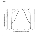
- the slope of the flanks of the course of a power distribution can be changed over the size H and on the sizes I and J, the curvature of the power curve can be influenced in its central region. This is based on the Fig. 4 illustrated and explained in more detail.
- the Fig. 4 shows in a graph the change in the profile of the power distribution of the resonator gem.
- Fig. 3 as a function of the location transverse to the guide direction of the printing material, ie in the same direction as Fig. 3a , on a standardized scale. Illustrated are, for example, a thick, solid line, a dashed line and a dotted line.
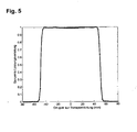
- Fig. 5 shows by type of FIG. 4 a nearly perfect rectangular shape of a power distribution of a resonator according to Fig. 3 , This special case is achieved with the dimensioning of the resonator with the values from the following Table 3.
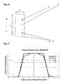
- a principle additional or alternative possibility of influencing the profile of a power distribution of a resonator in accordance with the invention is based on 6 and 7 explained.
- Fig. 6 shows a schematic sectional view of a known, simple hollow chamber resonator in the viewing direction and the type of representation of Fig. 3a ,
- the in Fig. 6 resonator shown again consists of two parts 1 and 2, which are separated by a gap 3 for carrying out the printing material.
- a microwave source can be connected to an aperture 8 from below.
- Fig. 7 are exemplary profile profiles with a dash-dotted line, a dashed line and a solid line for gap heights or widths L equal to 10 mm, equal to 5 mm or equal to 1.5 mm and the remaining dimensions shown in Table 4.
- the profile of the power distribution is increasingly rounded by the increasing gap width L.
- the desired profile taking into account the boundary conditions, such. B. accuracy of the path for the substrate and cooling, can be adjusted.
- the increased leakage radiation, which sets by broadening the gap 3 can be compensated by a matched to the respective gap width filter structure.
- this filter structure can be replaced by the fact that the gap 3 is closed laterally with a metal plate.
- the profile of the power distribution can also assume an asymmetrical shape for the design of the gap width. It is conceivable, for example, a vertically to the transport direction of the substrate continuously changed gap width, so that the profile on the side with the larger gap width correspondingly flatter than the profile on the side with the smaller gap width. This can be done so far that the outside in the path for the printing material positioned resonator on the outer side is completely closed, which is advantageous both for a lower emission to the outside and for a steeper profile increase on the closed side.
- An essential aspect of the dimensions is the width of the resonators. If a certain maximum substrate width is required for the fixer, the width of the individual resonators can be freely selected taking into account various boundary conditions.
- FIG. 3a in Fig. 8 indicated The sectional view of such a power splitter is suitable for the resonator according to FIG Fig. 3a in Fig. 8 indicated, to which the illustrated power splitter is attached from below in the region of the openings 4.
- the microwave source itself is again attached to the bottom of the power splitter.
- dimensions O, P and Q indicate height sections of the power splitter, which may be dimensioned according to the following Table 5, for example.
- the maximum width N is limited by the TE101 mode. If the width is too wide, other modes are capable of spreading and the heating profile is no longer maintained and takes unfavorable forms. Therefore, as the width increases, other design measures must be taken to maintain the TE101 mode in the resonator.
- FIG. 3 An embodiment for a larger width is according to Fig. 3 possible.
- two TE101 resonator hollow chamber regions 5 are coupled to one another via a large central opening above the dividing wall 6.
- the width of the individual resonators corresponds to the designated parameter D.
- a version with an even greater width of the TE 101 resonator hollow chamber regions is shown in FIG Fig. 9 shown. It can be seen that here four areas of width D are connected to each other. If the geometrical dimensions are chosen correctly, the power distribution can be adjusted analogously to the previously described one.
- Fig. 10 a power distribution that can be achieved with the following dimensions according to Table 6: ⁇ b> ⁇ u> Table 6: ⁇ / u> ⁇ /b> A 35 mm B 15 mm C 33 mm D 49.5 mm e 92 mm G 6 mm H 4.5 mm I 6 mm J 17 mm
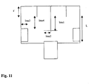
- Fig. 9 shown resonator of the power splitter in Fig. 11 called.
- This power splitter has the following dimensions according to Table 7: ⁇ b> ⁇ u> Table 7: ⁇ / u> ⁇ /b> L 58 mm I ' 28 mm LMS1 28.8 mm LMS2 35 mm LMS3 32.5 mm Lms4 25 mm
- width D it is possible to achieve even greater widths by attaching further resonators of width D and these are also coupled together via the larger opening and combined with each other.
- width in the transport direction of the printing material need not be kept constant, but may vary in this direction and thus create advantageous heating profiles.
- the width of the different resonators can also be chosen differently.
- a good arrangement results itself, if at different printing substrate widths, the lateral edge of the substrate is always transported only by a resonator, even if the position of the edge is different in each case.
- f r should be kept constant during these changes. This results in a change in the length (E) automatically a change in height (A + B + C). Suitable sizes of the parameter E are between 30 and 200 mm, preferably in the range between 60 and 100 mm.
Landscapes
- Physics & Mathematics (AREA)
- Electromagnetism (AREA)
- General Physics & Mathematics (AREA)
- Constitution Of High-Frequency Heating (AREA)
- Fixing For Electrophotography (AREA)
Claims (32)
- Procédé d'échauffement d'un support d'impression, en particulier avec du toner, notamment dans une imprimante fonctionnant en mode électrophotographique, avec au moins un faisceau de micro-ondes stationnaires produit par au moins un résonateur à enceinte creuse (1, 2), le support d'impression passant par une fente du résonateur et la répartition de la puissance du faisceau de micro-ondes appliqué par le résonateur étant conçue ou configurée de manière ciblée pour le besoin spécifique, caractérisé en ce que la face d'extrémité opposée à la face d'entrée des micro-ondes (4) du résonateur est obturée par un plafond d'enceinte (11) présentant une cavité (12) s'étendant dans la direction parallèle à la direction de guidage du support d'impression, et en ce que la profondeur de la cavité ou la largeur (l) d'un ou plusieurs bords de la cavité est ajustée transversalement à la direction de guidage du support d'impression.
- Procédé selon la revendication 1, caractérisé en ce que la répartition de la puissance est ajustée ou modifiée en fonction du lieu.
- Procédé selon la revendication 2, caractérisé en ce que la répartition de la puissance est ajustée ou modifiée sur la largeur transversalement à la direction de guidage du support d'impression.
- Procédé selon la revendication 2 ou 3, caractérisé en ce que la répartition de la puissance est ajustée en fonction du lieu de façon à créer sensiblement trois zones, soit deux zones entre une paroi du résonateur et vers le centre dans lesquelles la puissance augmente continuellement (front) et entre lesquelles se trouve une zone dont la forme suit une ligne plus ou moins recourbée de façon à créer sensiblement la forme d'un trapèze et en ce que la pente des fronts est ajustée ou modifiée.
- Procédé selon l'une quelconque des revendications 2 à 4, caractérisé en ce que la répartition de la puissance se fait sensiblement selon la forme d'un trapèze en fonction du lieu et en ce que la courbure de la zone de base centrale de ce trapèze est ajustée ou modifiée et ce, notamment dans sa courbure positive (convexe) ou négative (concave) ou pour l'absence d'une telle courbure (aplatissement).
- Procédé selon les revendications 4 et 5, caractérisé en ce que la courbe de la répartition de la puissance est ajustée de façon à avoir sensiblement une forme rectangulaire (forme π).
- Procédé selon la revendication 2 ou 3, caractérisé en ce que la répartition de la puissance est ajustée, en fonction du lieu, de manière asymétrique par rapport à l'axe central.
- Procédé selon l'une ou plusieurs des revendications précédentes, caractérisé en ce que la répartition de la puissance varie dans le temps.
- Procédé selon l'une ou plusieurs des revendications précédent, caractérisé en ce qu'au moins une grandeur géométrique du résonateur est ajustée ou modifiée, au moins relativement, par rapport à au moins une autre grandeur géométrique du résonateur.
- Procédé selon la revendication 9, caractérisé en ce que la largeur de la fente du résonateur est ajustée ou modifiée.
- Dispositif d'échauffement d'un support d'impression, en particulier avec du toner, notamment dans une imprimante fonctionnant en mode électrophotographique et comprenant au moins un résonateur avec au moins une enceinte creuse (1, 2) des micro-ondes émises par un émetteur, une source ou un générateur de micro-ondes produisant au moins un faisceau de micro-ondes stationnaires et comprenant une fente par laquelle le support d'impression passe, le résonateur étant conçu et configuré de manière ciblée pour une répartition de la puissance du faisceau de micro-ondes appliqué par le résonateur pour le besoin spécifique, caractérisé en ce que la face d'extrémité opposés à la face d'entrée des micro-ondes (4) du résonateur est obturée par un plafond d'enceinte (11) présentant une cavité (12) s'étendant dans la direction parallèle à la direction de guidage du support d'impression.
- Dispositif selon la revendication 11, caractérisé en ce que la répartition de la puissance est pré-ajustée ou ajustable en fonction du lieu.
- Dispositif selon la revendication 12, caractérisé en ce que la répartition de la puissance est pré-ajustée ou ajustable sur la largeur transversalement à la direction de guidage du support d'impression.
- Dispositif selon la revendication 11 ou 12, caractérisé en ce que la répartition de la puissance est ajustée en fonction du lieu de façon à créer sensiblement trois zones, soit deux zones entre une paroi du résonateur et vers le centre dans lesquelles la puissance augmente continuellement (front) et entre desquelles se trouve une zone dont la forme suit une ligne plus ou moins recourbée de façon à créer sensiblement la forme d'un trapèze et en ce que la pente des fronts est ajustée ou ajustable.
- Dispositif selon l'une quelconque des revendications 11 à 13, caractérisé en ce que la répartition de la puissance se fait sensiblement selon la forme d'un trapèze en fonction du lieu et en ce que la courbure de la zone de base centrale de ce trapèze est pré-ajustée ou ajustable et ce, notamment dans sa courbure positive (convexe) ou négative (concave) ou pour l'absence d'une telle courbure (aplatissement).
- Dispositif selon les revendications 14 et 15, caractérisé en ce que la courbe de la répartition de la puissance est pré-ajustée ou ajustable de façon à avoir sensiblement une forme rectangulaire (forme π).
- Dispositif selon la revendication 12 ou 13, caractérisé en ce que la répartition de la puissance est pré-ajustée ou ajustable de manière asymétrique en fonction du lieu.
- Dispositif selon l'une ou plusieurs des revendications 11 à 17, caractérisé en ce que la répartition de la puissance varie dans le temps.
- Dispositif selon l'une ou plusieurs des revendications 11 à 18, caractérisé en ce qu'au moins une grandeur géométrique du résonateur est pré-ajustée ou ajustable, au moins relativement par rapport à au moins une autre grandeur géométrique du résonateur.
- Dispositif selon la revendication 19, caractérisé en ce que la largeur de la fente du résonateur est pré-ajustée ou ajustable.
- Dispositif selon la revendications 11, caractérisé en ce que la cavité a approximativement la forme d'une raie dans le plafond passant d'une paroi de l'enceinte à l'autre.
- Dispositif selon la revendication 11 ou 21, caractérisé en ce que la profondeur de la cavité est pré-ajustée ou ajustable.
- Dispositif selon la revendication 11 ou 22, caractérisé en ce que la largeur d'un ou plusieurs bords de la cavité est pré-ajustée ou ajustable transversalement à la direction de guidage du support d'impression.
- Dispositif selon l'une quelconque des revendications 11 ou 22 à 23, caractérise en ce que la zone de l'enceinte creuse disposée de l'autre côté de la fente, vue de l'entrée des micro-ondes dans l'enceinte creuse, comprend au moins un rebord de col orienté vers l'ultérieur de l'enceinte creuse pour constituer une section de surface de délimitation.
- Dispositif selon l'une quelconque des revendications 11 à 24, caractérisé en ce que la zone de l'enceinte creuse disposée de ce côte-ci de la fente, vue de l'entrée des micro-ondes dans l'enceinte creuse, comprend au moins un rebord de col orienté vers l'intérieur de l'enceinte creuse pour constituer une section de surface de délimitation.
- Dispositif selon la revendication 24 ou 25, caractérisé en ce que la largeur d'un ou plusieurs rebords de col est pré-ajustée ou ajustable transversalement à la direction de guidage du support d'impression.
- Dispositif selon l'une quelconque des revendications 11 à 26, caractérisé en ce que la zone de l'enceinte creuse disposée en deçà de la fente, vue de l'entrée des micro-ondes dans l'enceinte creuse, comprend au moins une section de paroi divisant l'enceinte creuse au moins partiellement en plusieurs zones d'enceinte, cette section de paroi étant orientée parallèlement à la direction de guidage du support d'impression.
- Dispositif selon la revendication 27, caractérisé en ce qu'une source séparée de micro-ondes est associée à chacune de ces zones de l'enceinte.
- Dispositif selon la revendication 27, caractérisé en ce qu'une source de micro-ondes collective est associée à ces zones de l'enceinte, cette source disposant d'un répartiteur de puissance (power splitter) pour alimenter les zones de l'enceinte.
- Dispositif selon l'une quelconque des revendications 27 à 29, caractérisé en ce que la section de paroi comprend, sur au moins un côté, un diaphragme orienté parallèlement à la direction de guidage du support d'impression passant par la fente.
- Dispositif selon la revendication 30, caractérisé en ce que l'écartement entre le diaphragme et le bord de la section de paroi orienté vers la fente est pré-ajusté ou ajustable
- Dispositif selon l'une ou plusieurs des revendications 11 à 31, caractérisé en ce que le résonateur prévu est un applicateur TE101.
Applications Claiming Priority (4)
| Application Number | Priority Date | Filing Date | Title |
|---|---|---|---|
| DE10247798 | 2002-10-14 | ||
| DE10247798 | 2002-10-14 | ||
| DE10335024A DE10335024A1 (de) | 2002-10-14 | 2003-07-31 | Verfahren und Vorrichtung zur Erwärmung von Bedruckstoff und/oder Toner |
| DE10335024 | 2003-07-31 |
Publications (3)
| Publication Number | Publication Date |
|---|---|
| EP1411397A2 EP1411397A2 (fr) | 2004-04-21 |
| EP1411397A3 EP1411397A3 (fr) | 2006-05-10 |
| EP1411397B1 true EP1411397B1 (fr) | 2009-03-25 |
Family
ID=32043967
Family Applications (1)
| Application Number | Title | Priority Date | Filing Date |
|---|---|---|---|
| EP03018071A Expired - Lifetime EP1411397B1 (fr) | 2002-10-14 | 2003-08-08 | Méthode et dispositif pour chauffage d'un support d'enregistrement et/ou de toner |
Country Status (2)
| Country | Link |
|---|---|
| US (1) | US7022954B2 (fr) |
| EP (1) | EP1411397B1 (fr) |
Families Citing this family (3)
| Publication number | Priority date | Publication date | Assignee | Title |
|---|---|---|---|---|
| DE102004036827B4 (de) * | 2004-07-29 | 2009-11-26 | Eastman Kodak Co. | Mikrowellenheizvorrichtung |
| US7515859B2 (en) | 2007-04-24 | 2009-04-07 | Eastman Kodak Company | Power splitter for a microwave fuser of a reproduction apparatus |
| DE102009005358A1 (de) | 2009-01-16 | 2010-07-22 | Krones Ag | Resonatoreinheit, Expansionsverfahren und Vorrichtung zur Erwärmung von Behältnissen |
Family Cites Families (10)
| Publication number | Priority date | Publication date | Assignee | Title |
|---|---|---|---|---|
| BE776652A (fr) * | 1970-12-31 | 1972-04-04 | Soulier Joel H A | Dispositif pour l'uniformisation de l'energie d'hyperfrequence appliquee a une bande ou feuille a traiter a partir d'un cavite resonnante |
| US3851131A (en) | 1973-06-28 | 1974-11-26 | Canadian Patents Dev | Multimode microwave cavities for microwave heating systems |
| SE378057B (fr) | 1974-02-22 | 1975-08-11 | Stiftelsen Inst Mikrovags | |
| JPS5371340A (en) * | 1976-12-08 | 1978-06-24 | Hitachi Ltd | Dielectirc heater |
| US4435072A (en) * | 1980-12-11 | 1984-03-06 | Canon Kabushiki Kaisha | Image recording apparatus with leakage preventing microwave fixing device |
| US4625088A (en) | 1985-11-07 | 1986-11-25 | Gics Paul W | Center wall with sloped ends for a microwave heat applicator |
| FR2659518B1 (fr) * | 1990-03-07 | 1992-06-12 | Microondes Syst Sa | Dispositif applicateur d'ondes hyperfrequences pour le traitement de produits en feuille ou en nappe. |
| DE10145005C2 (de) * | 2000-12-22 | 2003-08-14 | Nexpress Solutions Llc | Verfahren und Einrichtung zur Fixierung von Toner auf einem Träger bzw. einem Bedruckstoff |
| DE10145002B8 (de) * | 2000-12-22 | 2006-12-28 | Eastman Kodak Co. | Verfahren und Einrichtung zur Fixierung von Toner auf einem Träger bzw. einem Bedruckstoff |
| US6938358B2 (en) * | 2002-02-15 | 2005-09-06 | International Business Machines Corporation | Method and apparatus for electromagnetic drying of printed media |
-
2003
- 2003-08-08 EP EP03018071A patent/EP1411397B1/fr not_active Expired - Lifetime
- 2003-09-17 US US10/664,510 patent/US7022954B2/en not_active Expired - Fee Related
Also Published As
| Publication number | Publication date |
|---|---|
| EP1411397A3 (fr) | 2006-05-10 |
| EP1411397A2 (fr) | 2004-04-21 |
| US20040226942A1 (en) | 2004-11-18 |
| US7022954B2 (en) | 2006-04-04 |
Similar Documents
| Publication | Publication Date | Title |
|---|---|---|
| DE19628952B4 (de) | Vorrichtung zur Erzeugung von Plasma | |
| DE69931502T2 (de) | Kollimator für strahlentherapiegerät | |
| DE69512601T2 (de) | Lichtstrahler | |
| DE3234100A1 (de) | Plasmalichtbogeneinrichtung zum auftragen von ueberzuegen | |
| DE69118121T2 (de) | Quadrupolmassenspektrometers | |
| DE2332116A1 (de) | Geraet zur bestrahlung eines bewegten produkts | |
| EP3669621A1 (fr) | Module de génération de plasma et utilisation dudit module | |
| DE2162727A1 (de) | Vorrichtung zur Vergleichmäßigung der an ein Band oder Blatt von einem Hohlraumresonator aus angelegten Hyperfrequenzenergie | |
| DE3045603A1 (de) | Verfahren und vorrichtung zur herstellung eines glasfilmes | |
| EP1411397B1 (fr) | Méthode et dispositif pour chauffage d'un support d'enregistrement et/ou de toner | |
| DE102012222469B4 (de) | Diffusionsgekühlte Gaslaseranordnung und Verfahren zur Einstellung der Entladungsverteilung bei einer diffusionsgekühlten Gaslaseranordnung | |
| DE1905770A1 (de) | Vorrichtung zum Plattieren von metallischen Werkstuecken mit Hilfe eines elektrischen Lichtbogens | |
| DE2001992B2 (de) | Mikrowellenherd | |
| DE10145005A1 (de) | Verfahren und Einrichtung zur Fixierung von Toner auf einem Träger bzw. einem Bedruckstoff | |
| DE3101488A1 (de) | Verfahren und vorrichtung zum elektrostatischen beschichten mit gesteuerter teilchenwolke | |
| DE69814043T2 (de) | Mikrowellenzufuhr in einem ofenkammer | |
| DE2224661B2 (de) | Mikrowellenofen Ausscheidung in: 2264616 und Ausscheidung in: 2264617 und Ausscheidung in: 2264618 und Ausscheidung in: 2264619 | |
| DE1597897B2 (de) | Verfahren und vorrichtung zum gleichfoermigen negativen aufladen einer flaeche mittels einer koronaentladung | |
| DE1030942B (de) | Induktor zur Oberflaechenhaertung von mit Zahnung versehenen Metallkoerpern od. dgl. | |
| DE10335024A1 (de) | Verfahren und Vorrichtung zur Erwärmung von Bedruckstoff und/oder Toner | |
| DE1598815A1 (de) | Einrichtung zur Messung des Feuchtigkeitsgehalts von Flaechenmaterial | |
| DE3416196C2 (fr) | ||
| DE10001936A1 (de) | Einkoppelanordnung für Mikrowellenenergie mit Impedanzanpassung | |
| WO1988010550A1 (fr) | Dispositif de cuisson electrique | |
| DE4304142C2 (de) | Kathode für eine Röntgenröhre |
Legal Events
| Date | Code | Title | Description |
|---|---|---|---|
| PUAI | Public reference made under article 153(3) epc to a published international application that has entered the european phase |
Free format text: ORIGINAL CODE: 0009012 |
|
| AK | Designated contracting states |
Kind code of ref document: A2 Designated state(s): AT BE BG CH CY CZ DE DK EE ES FI FR GB GR HU IE IT LI LU MC NL PT RO SE SI SK TR |
|
| AX | Request for extension of the european patent |
Extension state: AL LT LV MK |
|
| RAP1 | Party data changed (applicant data changed or rights of an application transferred) |
Owner name: EASTMAN KODAK COMPANY |
|
| PUAL | Search report despatched |
Free format text: ORIGINAL CODE: 0009013 |
|
| AK | Designated contracting states |
Kind code of ref document: A3 Designated state(s): AT BE BG CH CY CZ DE DK EE ES FI FR GB GR HU IE IT LI LU MC NL PT RO SE SI SK TR |
|
| AX | Request for extension of the european patent |
Extension state: AL LT LV MK |
|
| 17P | Request for examination filed |
Effective date: 20060517 |
|
| 17Q | First examination report despatched |
Effective date: 20061031 |
|
| AKX | Designation fees paid |
Designated state(s): AT BE BG CH CY CZ DE DK EE ES FI FR GB GR HU IE IT LI LU MC NL PT RO SE SI SK TR |
|
| RIN1 | Information on inventor provided before grant (corrected) |
Inventor name: ROHDE, DOMINGO Inventor name: CATALA-CIVERA, JOSE MANUEL Inventor name: BEHNKE, KNUT Inventor name: MORGENWECK, FRANK-MICHAEL Inventor name: SEIMETZ, LARS |
|
| GRAP | Despatch of communication of intention to grant a patent |
Free format text: ORIGINAL CODE: EPIDOSNIGR1 |
|
| GRAS | Grant fee paid |
Free format text: ORIGINAL CODE: EPIDOSNIGR3 |
|
| GRAA | (expected) grant |
Free format text: ORIGINAL CODE: 0009210 |
|
| AK | Designated contracting states |
Kind code of ref document: B1 Designated state(s): AT BE BG CH CY CZ DE DK EE ES FI FR GB GR HU IE IT LI LU MC NL PT RO SE SI SK TR |
|
| REG | Reference to a national code |
Ref country code: GB Ref legal event code: FG4D Free format text: NOT ENGLISH |
|
| REG | Reference to a national code |
Ref country code: CH Ref legal event code: EP |
|
| REG | Reference to a national code |
Ref country code: IE Ref legal event code: FG4D Free format text: LANGUAGE OF EP DOCUMENT: GERMAN |
|
| REF | Corresponds to: |
Ref document number: 50311332 Country of ref document: DE Date of ref document: 20090507 Kind code of ref document: P |
|
| PG25 | Lapsed in a contracting state [announced via postgrant information from national office to epo] |
Ref country code: SI Free format text: LAPSE BECAUSE OF FAILURE TO SUBMIT A TRANSLATION OF THE DESCRIPTION OR TO PAY THE FEE WITHIN THE PRESCRIBED TIME-LIMIT Effective date: 20090325 Ref country code: FI Free format text: LAPSE BECAUSE OF FAILURE TO SUBMIT A TRANSLATION OF THE DESCRIPTION OR TO PAY THE FEE WITHIN THE PRESCRIBED TIME-LIMIT Effective date: 20090325 |
|
| PG25 | Lapsed in a contracting state [announced via postgrant information from national office to epo] |
Ref country code: SE Free format text: LAPSE BECAUSE OF FAILURE TO SUBMIT A TRANSLATION OF THE DESCRIPTION OR TO PAY THE FEE WITHIN THE PRESCRIBED TIME-LIMIT Effective date: 20090625 |
|
| NLV1 | Nl: lapsed or annulled due to failure to fulfill the requirements of art. 29p and 29m of the patents act | ||
| REG | Reference to a national code |
Ref country code: IE Ref legal event code: FD4D |
|
| PG25 | Lapsed in a contracting state [announced via postgrant information from national office to epo] |
Ref country code: EE Free format text: LAPSE BECAUSE OF FAILURE TO SUBMIT A TRANSLATION OF THE DESCRIPTION OR TO PAY THE FEE WITHIN THE PRESCRIBED TIME-LIMIT Effective date: 20090325 Ref country code: CZ Free format text: LAPSE BECAUSE OF FAILURE TO SUBMIT A TRANSLATION OF THE DESCRIPTION OR TO PAY THE FEE WITHIN THE PRESCRIBED TIME-LIMIT Effective date: 20090325 Ref country code: PT Free format text: LAPSE BECAUSE OF FAILURE TO SUBMIT A TRANSLATION OF THE DESCRIPTION OR TO PAY THE FEE WITHIN THE PRESCRIBED TIME-LIMIT Effective date: 20090901 Ref country code: ES Free format text: LAPSE BECAUSE OF FAILURE TO SUBMIT A TRANSLATION OF THE DESCRIPTION OR TO PAY THE FEE WITHIN THE PRESCRIBED TIME-LIMIT Effective date: 20090706 |
|
| PG25 | Lapsed in a contracting state [announced via postgrant information from national office to epo] |
Ref country code: NL Free format text: LAPSE BECAUSE OF FAILURE TO SUBMIT A TRANSLATION OF THE DESCRIPTION OR TO PAY THE FEE WITHIN THE PRESCRIBED TIME-LIMIT Effective date: 20090325 Ref country code: RO Free format text: LAPSE BECAUSE OF FAILURE TO SUBMIT A TRANSLATION OF THE DESCRIPTION OR TO PAY THE FEE WITHIN THE PRESCRIBED TIME-LIMIT Effective date: 20090325 Ref country code: SK Free format text: LAPSE BECAUSE OF FAILURE TO SUBMIT A TRANSLATION OF THE DESCRIPTION OR TO PAY THE FEE WITHIN THE PRESCRIBED TIME-LIMIT Effective date: 20090325 |
|
| PG25 | Lapsed in a contracting state [announced via postgrant information from national office to epo] |
Ref country code: BG Free format text: LAPSE BECAUSE OF FAILURE TO SUBMIT A TRANSLATION OF THE DESCRIPTION OR TO PAY THE FEE WITHIN THE PRESCRIBED TIME-LIMIT Effective date: 20090625 Ref country code: IE Free format text: LAPSE BECAUSE OF FAILURE TO SUBMIT A TRANSLATION OF THE DESCRIPTION OR TO PAY THE FEE WITHIN THE PRESCRIBED TIME-LIMIT Effective date: 20090325 Ref country code: DK Free format text: LAPSE BECAUSE OF FAILURE TO SUBMIT A TRANSLATION OF THE DESCRIPTION OR TO PAY THE FEE WITHIN THE PRESCRIBED TIME-LIMIT Effective date: 20090325 |
|
| PLBE | No opposition filed within time limit |
Free format text: ORIGINAL CODE: 0009261 |
|
| STAA | Information on the status of an ep patent application or granted ep patent |
Free format text: STATUS: NO OPPOSITION FILED WITHIN TIME LIMIT |
|
| BERE | Be: lapsed |
Owner name: EASTMAN KODAK CY Effective date: 20090831 |
|
| 26N | No opposition filed |
Effective date: 20091229 |
|
| PG25 | Lapsed in a contracting state [announced via postgrant information from national office to epo] |
Ref country code: MC Free format text: LAPSE BECAUSE OF NON-PAYMENT OF DUE FEES Effective date: 20090831 |
|
| REG | Reference to a national code |
Ref country code: CH Ref legal event code: PL |
|
| PG25 | Lapsed in a contracting state [announced via postgrant information from national office to epo] |
Ref country code: CH Free format text: LAPSE BECAUSE OF NON-PAYMENT OF DUE FEES Effective date: 20090831 Ref country code: LI Free format text: LAPSE BECAUSE OF NON-PAYMENT OF DUE FEES Effective date: 20090831 |
|
| REG | Reference to a national code |
Ref country code: FR Ref legal event code: ST Effective date: 20100430 |
|
| PG25 | Lapsed in a contracting state [announced via postgrant information from national office to epo] |
Ref country code: BE Free format text: LAPSE BECAUSE OF NON-PAYMENT OF DUE FEES Effective date: 20090831 |
|
| PG25 | Lapsed in a contracting state [announced via postgrant information from national office to epo] |
Ref country code: FR Free format text: LAPSE BECAUSE OF NON-PAYMENT OF DUE FEES Effective date: 20090831 |
|
| PG25 | Lapsed in a contracting state [announced via postgrant information from national office to epo] |
Ref country code: GR Free format text: LAPSE BECAUSE OF FAILURE TO SUBMIT A TRANSLATION OF THE DESCRIPTION OR TO PAY THE FEE WITHIN THE PRESCRIBED TIME-LIMIT Effective date: 20090626 |
|
| PG25 | Lapsed in a contracting state [announced via postgrant information from national office to epo] |
Ref country code: AT Free format text: LAPSE BECAUSE OF NON-PAYMENT OF DUE FEES Effective date: 20090808 |
|
| PG25 | Lapsed in a contracting state [announced via postgrant information from national office to epo] |
Ref country code: IT Free format text: LAPSE BECAUSE OF FAILURE TO SUBMIT A TRANSLATION OF THE DESCRIPTION OR TO PAY THE FEE WITHIN THE PRESCRIBED TIME-LIMIT Effective date: 20090325 |
|
| PG25 | Lapsed in a contracting state [announced via postgrant information from national office to epo] |
Ref country code: LU Free format text: LAPSE BECAUSE OF NON-PAYMENT OF DUE FEES Effective date: 20090808 |
|
| PG25 | Lapsed in a contracting state [announced via postgrant information from national office to epo] |
Ref country code: HU Free format text: LAPSE BECAUSE OF FAILURE TO SUBMIT A TRANSLATION OF THE DESCRIPTION OR TO PAY THE FEE WITHIN THE PRESCRIBED TIME-LIMIT Effective date: 20090926 |
|
| PG25 | Lapsed in a contracting state [announced via postgrant information from national office to epo] |
Ref country code: TR Free format text: LAPSE BECAUSE OF FAILURE TO SUBMIT A TRANSLATION OF THE DESCRIPTION OR TO PAY THE FEE WITHIN THE PRESCRIBED TIME-LIMIT Effective date: 20090325 |
|
| PG25 | Lapsed in a contracting state [announced via postgrant information from national office to epo] |
Ref country code: CY Free format text: LAPSE BECAUSE OF FAILURE TO SUBMIT A TRANSLATION OF THE DESCRIPTION OR TO PAY THE FEE WITHIN THE PRESCRIBED TIME-LIMIT Effective date: 20090325 |
|
| PGFP | Annual fee paid to national office [announced via postgrant information from national office to epo] |
Ref country code: GB Payment date: 20120726 Year of fee payment: 10 |
|
| PGFP | Annual fee paid to national office [announced via postgrant information from national office to epo] |
Ref country code: DE Payment date: 20120831 Year of fee payment: 10 |
|
| GBPC | Gb: european patent ceased through non-payment of renewal fee |
Effective date: 20130808 |
|
| PG25 | Lapsed in a contracting state [announced via postgrant information from national office to epo] |
Ref country code: DE Free format text: LAPSE BECAUSE OF NON-PAYMENT OF DUE FEES Effective date: 20140301 |
|
| REG | Reference to a national code |
Ref country code: DE Ref legal event code: R119 Ref document number: 50311332 Country of ref document: DE Effective date: 20140301 |
|
| PG25 | Lapsed in a contracting state [announced via postgrant information from national office to epo] |
Ref country code: GB Free format text: LAPSE BECAUSE OF NON-PAYMENT OF DUE FEES Effective date: 20130808 |