EP1411420A1 - Méthode de détermination de coordonnées du point de contact pour utilisation dans un écran tactil résistif - Google Patents
Méthode de détermination de coordonnées du point de contact pour utilisation dans un écran tactil résistif Download PDFInfo
- Publication number
- EP1411420A1 EP1411420A1 EP20020022897 EP02022897A EP1411420A1 EP 1411420 A1 EP1411420 A1 EP 1411420A1 EP 20020022897 EP20020022897 EP 20020022897 EP 02022897 A EP02022897 A EP 02022897A EP 1411420 A1 EP1411420 A1 EP 1411420A1
- Authority
- EP
- European Patent Office
- Prior art keywords
- touch
- switch
- coordinate
- detecting
- resistor
- Prior art date
- Legal status (The legal status is an assumption and is not a legal conclusion. Google has not performed a legal analysis and makes no representation as to the accuracy of the status listed.)
- Granted
Links
Images



Classifications
-
- G—PHYSICS
- G06—COMPUTING OR CALCULATING; COUNTING
- G06F—ELECTRIC DIGITAL DATA PROCESSING
- G06F3/00—Input arrangements for transferring data to be processed into a form capable of being handled by the computer; Output arrangements for transferring data from processing unit to output unit, e.g. interface arrangements
- G06F3/01—Input arrangements or combined input and output arrangements for interaction between user and computer
- G06F3/03—Arrangements for converting the position or the displacement of a member into a coded form
- G06F3/041—Digitisers, e.g. for touch screens or touch pads, characterised by the transducing means
- G06F3/045—Digitisers, e.g. for touch screens or touch pads, characterised by the transducing means using resistive elements, e.g. a single continuous surface or two parallel surfaces put in contact
Definitions
- the invention relates in general to a touch panel, and more particularly to a method for detecting touch-point coordinate for use in a resistive touch panel.
- the Personal Digital Assistance becomes more and more popular than the conventional notebook due to its portability and multi-function.
- FIG. 1 A typical PDA 100 is shown in FIG. 1.
- the PDA 100 includes a base 102, a touch panel 104, a control switch 106, and a stylus 108, wherein the touch panel 104 is positioned on the top surface of the base 102.
- the user can operate the PDA 100 by touching the touch panel 104 with stylus 108.
- FIG. 2 illustrates a resistive touch panel formed with an X plate 202 and a Y plate 204 being disposed apart. Both the X plate 202 and the Y plate 204 are plane resistors and are not in contact with each other if no external force is exerted on the touch panel. As the user points the stylus to the touch panel, the point P1 of the X plate 202 is attached to point P2 of the Y plate 204, wherein the touched point on the touch panel corresponds to the point P1 on the X plate 202 and the point P2 on the Y plate.
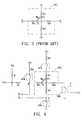
- FIG. 3 shows the equivalent circuit of the resistive touch panel, wherein the equivalent resistor R M is produced between the X plate and the Y plate.
- the equivalent resistor R M is produced between the X plate and the Y plate.
- equivalent resistors R xo and R x1 on the X plate are coupled to the point P2, wherein the magnitude of the R xo and R x1 are determined by the X-coordinate of the point P2, not the Y-coordinate of the point P2.
- the two equivalent resistor R yo and R y1 on the Y plate are coupled to the point P1, wherein the magnitude of the R yo and R y1 are determined by the Y-coordinate of the point P1, not the X-coordinate of the point P2.
- a touch-point detecting apparatus is employed to determine the coordinates of the touched point on the touch panel. If the stylus touches the touch panel too lightly, the contact status between the Y plate and the X plate will be unstable, and the corresponding equivalent resistor R M will be different with that resulting from normally pressed. In this case, the detection result is in error and accordingly may cause the PDA to operate in wrong status.
- a touch-point detecting method is disclosed, wherein the touch-point detecting apparatus comprises a plurality of switches and a plurality of external resistors, and is coupled to two power supplies and two touch-panel resistors of the touch panel. The two power supplies are used for respectively applying constant voltages to two touch-panel resistors.
- the touch-point detecting method comprises the steps of: determining whether an external force is exerted on the resistive touch panel according to a pressure detection signal, if so, proceeding to the next step; determining whether the external force is effective according to a first signal and a second signal that are produced by a comparing process, if so, proceeding with the next step; producing a first coordinate signal by performing first-coordinate detecting of a touch point at which the external force is exerted on the resistive touch panel, wherein the first coordinate signal indicates a first coordinate of the touch point; producing a second coordinate signal by performing second-coordinate detecting of the touch point at which the external force is exerted on the resistive touch panel, wherein the second coordinate signal indicates a second coordinate of the touch point.
- FIG. 1 shows a PDA
- FIG. 2 illustrates the structure of a typical resistive touch panel.
- FIG. 3 shows the equivalent circuit of the resistive touch panel, wherein the equivalent resistor R M is produced between the X plate and the Y plate.
- FIG. 4 shows the equivalent circuit of the touch-point detecting apparatus for the resistive touch panel according to the preferred embodiment of the present invention.
- FIG. 5 shows the equivalent circuit of the touch-point detecting apparatus during the step of determining whether an external force is exerted on the touch panel.
- FIG. 6 shows the equivalent circuit of the touch-point position-test apparatus during the step of determining whether the external force is effective external force.
- FIG. 7A shows the equivalent circuit of the touch-point detecting apparatus during the step of detecting X-coordinate of the touch point.
- FIG. 7B shows the equivalent circuit of the touch-point detecting apparatus during the step of detecting Y-coordinate of the touch point.
- FIG. 8 shows the flow chart of the preferred embodiment for the touch-point detecting method.
- FIG. 9 shows the equivalent circuit of another touch-point detecting apparatus, wherein the configuration are almost the same as that in FIG. 4, except signals from the touch-point detecting apparatus pass through nodes C, D, and E.
- FIG. 4 shows an equivalent circuit of a touch-point location detecting apparatus for a resistive touch panel 402 according to the preferred embodiment of the present invention.
- nodes A, B, C are used as the output terminals of the touch-point detecting apparatus. These nodes can be connected to the post-stage signal processing apparatus, for example.
- the touch-point detecting apparatus is coupled to the external power supplies V CX , V CY and the resistive touch panel 402, and comprises switches 404, 406, 408, 410, and external resistors R PX , R PY , R 1 , and R 2 , wherein switches 404, 408 are coupled to the X plate, switches 406, 410 are coupled to the Y plate, and switches 404, 410 are respectively coupled to the external resistors R PX , R PY .
- the external powers V CX , V CY are, respectively, coupled to the external resistors R PX , R PY for supplying constant voltage to the X plate and the Y plate.
- the external resistor R 2 is coupled to the external resistor R 1 and one of the X plate and the Y plate. In this embodiment, the external resistor R 2 is coupled to the X plate.
- the touch-point location detecting method comprises four steps: determining whether an external force is exerted on the touch panel 402, determining whether the external force is effective external force, detecting X-coordinate of the touch point, and detecting Y-coordinate of the touch point.
- the equivalent circuits, corresponding to the four steps, are respectively shown in FIG. 5, FIG, 6, FIG. 7A, and FIG. 7B.
- FIG. 5 illustrates the equivalent circuit of the touch-point apparatus during the step of determining whether an external force is exerted on the touch panel 402, wherein switch 406 is enabled and switches 404, 408, 410 are disabled.
- the voltage Vc at the node C will be equal to Vcc, corresponding to a logic HIGH, owing to the resistance of the equivalent resistor R M across the two plates being infinite.
- the voltage signal TP at the node C will be much lower than Vcc, corresponding to a logic LOW, due to the formation of the loop across the X and Y planes with the finite equivalent resistor R M produced in the contact thereof. Therefore, a detecting as to whether an external force is exerted on the touch panel can be made according to the voltage signal TP.
- FIG. 6 illustrates the equivalent circuit of the touch-point detecting apparatus during the step of determining whether the external force is effective external force, wherein switches 408, 410 are enabled and switches 404, 406 are disabled.
- the voltage signals TX, TY are outputted from nodes A and B, respectively. If an external force is normally exerted on the touch panel, the resistance of the equivalent resistor R M and the difference between the voltage signals TX and TY will be much smaller than those resulting from no external force. If an external force is lightly exerted on the touch panel 402, the resistance of the equivalent resistor R M and the voltage difference will be larger than those resulting from a normal external force and smaller than those resulting from no external force.
- the voltage difference between the voltage signals TX and TY is compared with the predetermined threshold value of the voltage difference so as to determine whether the external force is effective.
- the external force will be determined as an effective external force if the voltage difference between the voltage signals TX and TY is smaller than the pre-determined threshold value. Conversely, the external force will not be regarded as an effective external force to indicate instructions if the voltage difference between the voltage signals TX and TY is larger than the pre-determined threshold.
- the touch-point detecting apparatus ends the touch-point detecting method, which can avoid any erroneous operation and erroneous display resulting from error voltage signals TX or TY.
- FIG. 7A illustrates the equivalent circuit of the touch-point detecting apparatus during the step of detecting the X-coordinate of the touch point, wherein switches 404, 408 are enabled and switches 406, 410 are disabled.
- the voltage V A at node A relates to the ratio of equivalent resistor R X0 to equivalent resistor R X1 on the X plate, wherein the ratio is determined by the X-coordinate. Therefore, the voltage signal TX at the node A indicates the X-coordinate of a touch point on which the external force is exerted.
- FIG. 7B shows the equivalent circuit of the touch-point detecting apparatus during the step of detecting the Y-coordinate of the touch point, wherein switches 406, 410 are enabled and switches 404, 408 are disabled.
- the voltage V B on node B is related with the ratio of equivalent resistor R Y0 to equivalent resistor R Y1 on the Y plate, wherein the ratio is determined by the Y-coordinate. Therefore, the voltage signal TY outputted from the node B indicates the Y-coordinate, on which the external force is imposed on the touch panel 402.
- the touch-point detecting method is not limited to implementing the step of detecting X-coordinate first and then the step of detecting Y-coordinate. To interchange these two steps is also applicable in the present invention.
- the step of determining whether the external force is effective external force can also be implemented between the steps of detecting X-coordinate and detecting Y-coordinate again and after the two coordination-drawing steps.
- the pressure comparison step for determining whether the external force is effective external force can be implemented for three times, between which other steps of the present method can be implemented.
- all embodiments of the touch-point detecting method comprises the sequences of CXY (CYX), XCY (YCX), XYC (YXC), CXCY (CYCX), CXYC (CYXC), XCYC (YCXC), CXCYC (CYCXC), wherein the C, X and Y represent the steps of determining whether the external force is effective external force, detecting X-coordinate of the touch point, and detecting Y-coordinate of the touch point respectively.
- step 802 of pressure detection the touch-point detecting apparatus determines whether an external force is exerted on the touch panel. If not, the method is finished. If so, then the step 804 is executed. In step 804, whether the external force is effective external force. Next, producing a first coordinate and producing a second coordinate are respectively executed in step 806 and step 808, wherein the first coordinate can be X-coordinate or Y-coordinate. Please note that the step 804 of pressure comparison is executed between step 806 and step 808 again, and after the step 808.
- FIG. 9 is an equivalent circuit of another touch-point detecting apparatus with a resistive touch panel, according to the invention.
- the configuration of this touch-point detecting apparatus in FIG. 9 is almost the same as that in FIG. 4, except that output signals of this example are provided through nodes C, D, and E.
- the difference of the voltage signals outputted from the node D and node E, by enabling switches 404, 406, and disabling switches 408, 410 is compared with the a predetermined threshold value to determine if the external force is effective or not.
- the voltage signal TX is outputted from node D by enabling switch 404, 408 and disabling switch 406, 410.
- the voltage signal TY is outputted from node E by enabling switch 406, 410 and disabling switch 404, 408. The remaining step is the same as the previous embodiment.
- the position, which an external force is exerted on the resistive touch panel is detected by selectively enabling switches of the touch-point detecting apparatus.
- the present invention will determine whether an external force is exerted on the touch panel and further check if the external force is effective or not.
- the touch-point detecting method of the present invention can solve the problem that no bright point appears on the display or the bright point appears on the wrong position when the external force is too small.
Landscapes
- Engineering & Computer Science (AREA)
- General Engineering & Computer Science (AREA)
- Theoretical Computer Science (AREA)
- Human Computer Interaction (AREA)
- Physics & Mathematics (AREA)
- General Physics & Mathematics (AREA)
- Position Input By Displaying (AREA)
- User Interface Of Digital Computer (AREA)
Priority Applications (3)
| Application Number | Priority Date | Filing Date | Title |
|---|---|---|---|
| DE60224051T DE60224051T2 (de) | 2002-10-14 | 2002-10-14 | Verfahren zur Detektion von Koordinaten des Tastpunktes zur Verwendung mit einem berührungsempfindlichen Widerstandbildschirm |
| AT02022897T ATE381054T1 (de) | 2002-10-14 | 2002-10-14 | Verfahren zur detektion von koordinaten des tastpunktes zur verwendung mit einem berührungsempfindlichen widerstandbildschirm |
| EP02022897A EP1411420B1 (fr) | 2002-10-14 | 2002-10-14 | Méthode de détermination de coordonnées du point de contact pour utilisation dans un écran tactil résistif |
Applications Claiming Priority (1)
| Application Number | Priority Date | Filing Date | Title |
|---|---|---|---|
| EP02022897A EP1411420B1 (fr) | 2002-10-14 | 2002-10-14 | Méthode de détermination de coordonnées du point de contact pour utilisation dans un écran tactil résistif |
Publications (2)
| Publication Number | Publication Date |
|---|---|
| EP1411420A1 true EP1411420A1 (fr) | 2004-04-21 |
| EP1411420B1 EP1411420B1 (fr) | 2007-12-12 |
Family
ID=32039129
Family Applications (1)
| Application Number | Title | Priority Date | Filing Date |
|---|---|---|---|
| EP02022897A Expired - Lifetime EP1411420B1 (fr) | 2002-10-14 | 2002-10-14 | Méthode de détermination de coordonnées du point de contact pour utilisation dans un écran tactil résistif |
Country Status (3)
| Country | Link |
|---|---|
| EP (1) | EP1411420B1 (fr) |
| AT (1) | ATE381054T1 (fr) |
| DE (1) | DE60224051T2 (fr) |
Cited By (3)
| Publication number | Priority date | Publication date | Assignee | Title |
|---|---|---|---|---|
| EP2164303A3 (fr) * | 2006-06-20 | 2010-04-21 | Lutron Electronics Co., Inc. | Organe de commande tactile à force invariante |
| FR2945361A1 (fr) * | 2009-05-05 | 2010-11-12 | Magneti Marelli France | Procede de validation et d'elimination de determination de donnees de coordonnees erronees pour dalle tactile resistive |
| EP3073354A1 (fr) | 2015-03-24 | 2016-09-28 | Vestel Elektronik Sanayi ve Ticaret A.S. | Procédé de détection de toucher |
Citations (4)
| Publication number | Priority date | Publication date | Assignee | Title |
|---|---|---|---|---|
| EP0309946A2 (fr) * | 1987-09-28 | 1989-04-05 | Oki Electric Industry Company, Limited | Appareil pour l'entrée de données sensible à la pression |
| US5453941A (en) * | 1993-04-23 | 1995-09-26 | Smk Corporation | Method and device for detecting and measuring pressure and coordinates in pressure-sensitive pads |
| US5659154A (en) * | 1993-04-23 | 1997-08-19 | Smk Corporation | Method and apparatus for coordinate detection |
| US20020101407A1 (en) * | 2001-01-31 | 2002-08-01 | Mobigence, Inc. | Touch panel coordinate determination |
-
2002
- 2002-10-14 AT AT02022897T patent/ATE381054T1/de not_active IP Right Cessation
- 2002-10-14 EP EP02022897A patent/EP1411420B1/fr not_active Expired - Lifetime
- 2002-10-14 DE DE60224051T patent/DE60224051T2/de not_active Expired - Lifetime
Patent Citations (4)
| Publication number | Priority date | Publication date | Assignee | Title |
|---|---|---|---|---|
| EP0309946A2 (fr) * | 1987-09-28 | 1989-04-05 | Oki Electric Industry Company, Limited | Appareil pour l'entrée de données sensible à la pression |
| US5453941A (en) * | 1993-04-23 | 1995-09-26 | Smk Corporation | Method and device for detecting and measuring pressure and coordinates in pressure-sensitive pads |
| US5659154A (en) * | 1993-04-23 | 1997-08-19 | Smk Corporation | Method and apparatus for coordinate detection |
| US20020101407A1 (en) * | 2001-01-31 | 2002-08-01 | Mobigence, Inc. | Touch panel coordinate determination |
Cited By (7)
| Publication number | Priority date | Publication date | Assignee | Title |
|---|---|---|---|---|
| EP2164303A3 (fr) * | 2006-06-20 | 2010-04-21 | Lutron Electronics Co., Inc. | Organe de commande tactile à force invariante |
| US7855543B2 (en) | 2006-06-20 | 2010-12-21 | Lutron Electronics Co., Inc. | Force invariant touch sensitive actuator |
| US8040080B2 (en) | 2006-06-20 | 2011-10-18 | Lutron Electronics Co., Inc. | Force invariant touch sensitive actuator |
| US8098029B2 (en) | 2006-06-20 | 2012-01-17 | Lutron Electronics Co., Inc. | Force invariant touch sensitive actuator |
| FR2945361A1 (fr) * | 2009-05-05 | 2010-11-12 | Magneti Marelli France | Procede de validation et d'elimination de determination de donnees de coordonnees erronees pour dalle tactile resistive |
| EP2251773A1 (fr) * | 2009-05-05 | 2010-11-17 | Magneti Marelli France | Procedé de validation de données de coordonnées déterminées par une dalle tactile resistive, et d'élimination de données de coordonnées erronées |
| EP3073354A1 (fr) | 2015-03-24 | 2016-09-28 | Vestel Elektronik Sanayi ve Ticaret A.S. | Procédé de détection de toucher |
Also Published As
| Publication number | Publication date |
|---|---|
| EP1411420B1 (fr) | 2007-12-12 |
| DE60224051T2 (de) | 2008-11-20 |
| DE60224051D1 (de) | 2008-01-24 |
| ATE381054T1 (de) | 2007-12-15 |
Similar Documents
| Publication | Publication Date | Title |
|---|---|---|
| US6975307B2 (en) | Method for detecting touch-point coordinate for use in a resistive touch panel | |
| US8125464B2 (en) | Full scale calibration measurement for multi-touch surfaces | |
| US6738048B1 (en) | Touch screen controller | |
| CN105556443B (zh) | 使用动态阈值对压感板的点击检测的方法和设备 | |
| US8305357B2 (en) | Method for detecting multiple touch positions on a touch panel | |
| EP2284669B1 (fr) | Panneau tactile et son procédé de sortie | |
| US20090085888A1 (en) | Resistive multi-touch panel and detecting method thereof | |
| US10169633B2 (en) | Driving circuit, driving method, display apparatus and electronic apparatus | |
| US20080117178A1 (en) | Electronic devices having a touch screen and method for starting the electronic devices | |
| US9910543B2 (en) | Apparatus for improving signal-to-noise performance of projected capacitance touch screens and panels | |
| CN1178158C (zh) | 用于电阻式触控板的触压点坐标检测方法 | |
| WO2021036718A1 (fr) | Procédé et dispositif de détermination de point de contact | |
| EP1411420B1 (fr) | Méthode de détermination de coordonnées du point de contact pour utilisation dans un écran tactil résistif | |
| KR100480155B1 (ko) | 다중 터치패널의 구동방법, 구동장치 및 그를 사용한 다중터치패널 장치 | |
| US6344847B1 (en) | Coordinate detection device | |
| JP2014044680A (ja) | ハイブリッドタッチパネル | |
| US20080158187A1 (en) | Touch control input system for use in electronic apparatuses and signal generation method thereof | |
| JPH09330167A (ja) | ポインティング入力装置 | |
| US10558306B2 (en) | In-cell touch apparatus and a water mode detection method thereof | |
| KR20090036780A (ko) | 터치판넬 입력 장치 및 방법 | |
| KR100988724B1 (ko) | 터치 스크린 및 그 터치 감지 방법 | |
| JP2973925B2 (ja) | タッチパッド入力装置 | |
| JP2001043003A (ja) | タッチパネル入力装置 | |
| TWI492135B (zh) | 單層多點互容式觸控面板之驅動感應方法 | |
| TW201310297A (zh) | 駐極體輸入裝置及其操作方法 |
Legal Events
| Date | Code | Title | Description |
|---|---|---|---|
| PUAI | Public reference made under article 153(3) epc to a published international application that has entered the european phase |
Free format text: ORIGINAL CODE: 0009012 |
|
| AK | Designated contracting states |
Kind code of ref document: A1 Designated state(s): AT BE BG CH CY CZ DE DK EE ES FI FR GB GR IE IT LI LU MC NL PT SE SK TR |
|
| AX | Request for extension of the european patent |
Extension state: AL LT LV MK RO SI |
|
| RIN1 | Information on inventor provided before grant (corrected) |
Inventor name: SHU-HUNG, TSENG Inventor name: YUAN-JIE, SHIANG Inventor name: CHANG-MIEN, YANG Inventor name: WEI-CHIH, CHANG |
|
| 17P | Request for examination filed |
Effective date: 20040603 |
|
| AKX | Designation fees paid |
Designated state(s): AT BE BG CH CY CZ DE DK EE ES FI FR GB GR IE IT LI LU MC NL PT SE SK TR |
|
| GRAP | Despatch of communication of intention to grant a patent |
Free format text: ORIGINAL CODE: EPIDOSNIGR1 |
|
| GRAS | Grant fee paid |
Free format text: ORIGINAL CODE: EPIDOSNIGR3 |
|
| GRAA | (expected) grant |
Free format text: ORIGINAL CODE: 0009210 |
|
| AK | Designated contracting states |
Kind code of ref document: B1 Designated state(s): AT BE BG CH CY CZ DE DK EE ES FI FR GB GR IE IT LI LU MC NL PT SE SK TR |
|
| REG | Reference to a national code |
Ref country code: GB Ref legal event code: FG4D |
|
| REG | Reference to a national code |
Ref country code: CH Ref legal event code: EP |
|
| REG | Reference to a national code |
Ref country code: IE Ref legal event code: FG4D |
|
| REF | Corresponds to: |
Ref document number: 60224051 Country of ref document: DE Date of ref document: 20080124 Kind code of ref document: P |
|
| PG25 | Lapsed in a contracting state [announced via postgrant information from national office to epo] |
Ref country code: CH Free format text: LAPSE BECAUSE OF FAILURE TO SUBMIT A TRANSLATION OF THE DESCRIPTION OR TO PAY THE FEE WITHIN THE PRESCRIBED TIME-LIMIT Effective date: 20071212 Ref country code: SE Free format text: LAPSE BECAUSE OF FAILURE TO SUBMIT A TRANSLATION OF THE DESCRIPTION OR TO PAY THE FEE WITHIN THE PRESCRIBED TIME-LIMIT Effective date: 20080312 Ref country code: LI Free format text: LAPSE BECAUSE OF FAILURE TO SUBMIT A TRANSLATION OF THE DESCRIPTION OR TO PAY THE FEE WITHIN THE PRESCRIBED TIME-LIMIT Effective date: 20071212 |
|
| PG25 | Lapsed in a contracting state [announced via postgrant information from national office to epo] |
Ref country code: FI Free format text: LAPSE BECAUSE OF FAILURE TO SUBMIT A TRANSLATION OF THE DESCRIPTION OR TO PAY THE FEE WITHIN THE PRESCRIBED TIME-LIMIT Effective date: 20071212 |
|
| REG | Reference to a national code |
Ref country code: CH Ref legal event code: PL |
|
| PG25 | Lapsed in a contracting state [announced via postgrant information from national office to epo] |
Ref country code: AT Free format text: LAPSE BECAUSE OF FAILURE TO SUBMIT A TRANSLATION OF THE DESCRIPTION OR TO PAY THE FEE WITHIN THE PRESCRIBED TIME-LIMIT Effective date: 20071212 |
|
| PG25 | Lapsed in a contracting state [announced via postgrant information from national office to epo] |
Ref country code: CZ Free format text: LAPSE BECAUSE OF FAILURE TO SUBMIT A TRANSLATION OF THE DESCRIPTION OR TO PAY THE FEE WITHIN THE PRESCRIBED TIME-LIMIT Effective date: 20071212 Ref country code: ES Free format text: LAPSE BECAUSE OF FAILURE TO SUBMIT A TRANSLATION OF THE DESCRIPTION OR TO PAY THE FEE WITHIN THE PRESCRIBED TIME-LIMIT Effective date: 20080323 |
|
| ET | Fr: translation filed | ||
| PG25 | Lapsed in a contracting state [announced via postgrant information from national office to epo] |
Ref country code: SK Free format text: LAPSE BECAUSE OF FAILURE TO SUBMIT A TRANSLATION OF THE DESCRIPTION OR TO PAY THE FEE WITHIN THE PRESCRIBED TIME-LIMIT Effective date: 20071212 Ref country code: BE Free format text: LAPSE BECAUSE OF FAILURE TO SUBMIT A TRANSLATION OF THE DESCRIPTION OR TO PAY THE FEE WITHIN THE PRESCRIBED TIME-LIMIT Effective date: 20071212 |
|
| PG25 | Lapsed in a contracting state [announced via postgrant information from national office to epo] |
Ref country code: PT Free format text: LAPSE BECAUSE OF FAILURE TO SUBMIT A TRANSLATION OF THE DESCRIPTION OR TO PAY THE FEE WITHIN THE PRESCRIBED TIME-LIMIT Effective date: 20080512 |
|
| PLBE | No opposition filed within time limit |
Free format text: ORIGINAL CODE: 0009261 |
|
| STAA | Information on the status of an ep patent application or granted ep patent |
Free format text: STATUS: NO OPPOSITION FILED WITHIN TIME LIMIT |
|
| PG25 | Lapsed in a contracting state [announced via postgrant information from national office to epo] |
Ref country code: DK Free format text: LAPSE BECAUSE OF FAILURE TO SUBMIT A TRANSLATION OF THE DESCRIPTION OR TO PAY THE FEE WITHIN THE PRESCRIBED TIME-LIMIT Effective date: 20071212 |
|
| 26N | No opposition filed |
Effective date: 20080915 |
|
| PG25 | Lapsed in a contracting state [announced via postgrant information from national office to epo] |
Ref country code: GR Free format text: LAPSE BECAUSE OF FAILURE TO SUBMIT A TRANSLATION OF THE DESCRIPTION OR TO PAY THE FEE WITHIN THE PRESCRIBED TIME-LIMIT Effective date: 20080313 |
|
| PG25 | Lapsed in a contracting state [announced via postgrant information from national office to epo] |
Ref country code: EE Free format text: LAPSE BECAUSE OF FAILURE TO SUBMIT A TRANSLATION OF THE DESCRIPTION OR TO PAY THE FEE WITHIN THE PRESCRIBED TIME-LIMIT Effective date: 20071212 Ref country code: BG Free format text: LAPSE BECAUSE OF FAILURE TO SUBMIT A TRANSLATION OF THE DESCRIPTION OR TO PAY THE FEE WITHIN THE PRESCRIBED TIME-LIMIT Effective date: 20080312 |
|
| PG25 | Lapsed in a contracting state [announced via postgrant information from national office to epo] |
Ref country code: MC Free format text: LAPSE BECAUSE OF NON-PAYMENT OF DUE FEES Effective date: 20081031 |
|
| PG25 | Lapsed in a contracting state [announced via postgrant information from national office to epo] |
Ref country code: CY Free format text: LAPSE BECAUSE OF FAILURE TO SUBMIT A TRANSLATION OF THE DESCRIPTION OR TO PAY THE FEE WITHIN THE PRESCRIBED TIME-LIMIT Effective date: 20071212 |
|
| PG25 | Lapsed in a contracting state [announced via postgrant information from national office to epo] |
Ref country code: IE Free format text: LAPSE BECAUSE OF NON-PAYMENT OF DUE FEES Effective date: 20081014 |
|
| PG25 | Lapsed in a contracting state [announced via postgrant information from national office to epo] |
Ref country code: LU Free format text: LAPSE BECAUSE OF NON-PAYMENT OF DUE FEES Effective date: 20081014 |
|
| PG25 | Lapsed in a contracting state [announced via postgrant information from national office to epo] |
Ref country code: TR Free format text: LAPSE BECAUSE OF FAILURE TO SUBMIT A TRANSLATION OF THE DESCRIPTION OR TO PAY THE FEE WITHIN THE PRESCRIBED TIME-LIMIT Effective date: 20071212 |
|
| PG25 | Lapsed in a contracting state [announced via postgrant information from national office to epo] |
Ref country code: IT Free format text: LAPSE BECAUSE OF NON-PAYMENT OF DUE FEES Effective date: 20081031 |
|
| REG | Reference to a national code |
Ref country code: FR Ref legal event code: PLFP Year of fee payment: 14 |
|
| REG | Reference to a national code |
Ref country code: FR Ref legal event code: PLFP Year of fee payment: 15 |
|
| REG | Reference to a national code |
Ref country code: FR Ref legal event code: PLFP Year of fee payment: 16 |
|
| REG | Reference to a national code |
Ref country code: FR Ref legal event code: PLFP Year of fee payment: 17 |
|
| PGFP | Annual fee paid to national office [announced via postgrant information from national office to epo] |
Ref country code: FR Payment date: 20190913 Year of fee payment: 18 |
|
| PGFP | Annual fee paid to national office [announced via postgrant information from national office to epo] |
Ref country code: DE Payment date: 20191001 Year of fee payment: 18 Ref country code: NL Payment date: 20191014 Year of fee payment: 18 |
|
| PGFP | Annual fee paid to national office [announced via postgrant information from national office to epo] |
Ref country code: GB Payment date: 20191010 Year of fee payment: 18 |
|
| REG | Reference to a national code |
Ref country code: DE Ref legal event code: R119 Ref document number: 60224051 Country of ref document: DE |
|
| REG | Reference to a national code |
Ref country code: NL Ref legal event code: MM Effective date: 20201101 |
|
| GBPC | Gb: european patent ceased through non-payment of renewal fee |
Effective date: 20201014 |
|
| PG25 | Lapsed in a contracting state [announced via postgrant information from national office to epo] |
Ref country code: FR Free format text: LAPSE BECAUSE OF NON-PAYMENT OF DUE FEES Effective date: 20201031 Ref country code: DE Free format text: LAPSE BECAUSE OF NON-PAYMENT OF DUE FEES Effective date: 20210501 Ref country code: NL Free format text: LAPSE BECAUSE OF NON-PAYMENT OF DUE FEES Effective date: 20201101 |
|
| PG25 | Lapsed in a contracting state [announced via postgrant information from national office to epo] |
Ref country code: GB Free format text: LAPSE BECAUSE OF NON-PAYMENT OF DUE FEES Effective date: 20201014 |