EP1411468A1 - Vorrichtung zur Kontrolle eines Codes auf Entfernung - Google Patents
Vorrichtung zur Kontrolle eines Codes auf Entfernung Download PDFInfo
- Publication number
- EP1411468A1 EP1411468A1 EP03356148A EP03356148A EP1411468A1 EP 1411468 A1 EP1411468 A1 EP 1411468A1 EP 03356148 A EP03356148 A EP 03356148A EP 03356148 A EP03356148 A EP 03356148A EP 1411468 A1 EP1411468 A1 EP 1411468A1
- Authority
- EP
- European Patent Office
- Prior art keywords
- antenna
- strip
- electronic chip
- tongue
- adhesive sheet
- Prior art date
- Legal status (The legal status is an assumption and is not a legal conclusion. Google has not performed a legal analysis and makes no representation as to the accuracy of the status listed.)
- Withdrawn
Links
Images



Classifications
-
- G—PHYSICS
- G06—COMPUTING OR CALCULATING; COUNTING
- G06K—GRAPHICAL DATA READING; PRESENTATION OF DATA; RECORD CARRIERS; HANDLING RECORD CARRIERS
- G06K19/00—Record carriers for use with machines and with at least a part designed to carry digital markings
- G06K19/06—Record carriers for use with machines and with at least a part designed to carry digital markings characterised by the kind of the digital marking, e.g. shape, nature, code
- G06K19/067—Record carriers with conductive marks, printed circuits or semiconductor circuit elements, e.g. credit or identity cards also with resonating or responding marks without active components
- G06K19/07—Record carriers with conductive marks, printed circuits or semiconductor circuit elements, e.g. credit or identity cards also with resonating or responding marks without active components with integrated circuit chips
- G06K19/077—Constructional details, e.g. mounting of circuits in the carrier
- G06K19/07749—Constructional details, e.g. mounting of circuits in the carrier the record carrier being capable of non-contact communication, e.g. constructional details of the antenna of a non-contact smart card
- G06K19/07758—Constructional details, e.g. mounting of circuits in the carrier the record carrier being capable of non-contact communication, e.g. constructional details of the antenna of a non-contact smart card arrangements for adhering the record carrier to further objects or living beings, functioning as an identification tag
- G06K19/07762—Constructional details, e.g. mounting of circuits in the carrier the record carrier being capable of non-contact communication, e.g. constructional details of the antenna of a non-contact smart card arrangements for adhering the record carrier to further objects or living beings, functioning as an identification tag the adhering arrangement making the record carrier wearable, e.g. having the form of a ring, watch, glove or bracelet
-
- G—PHYSICS
- G06—COMPUTING OR CALCULATING; COUNTING
- G06K—GRAPHICAL DATA READING; PRESENTATION OF DATA; RECORD CARRIERS; HANDLING RECORD CARRIERS
- G06K19/00—Record carriers for use with machines and with at least a part designed to carry digital markings
- G06K19/06—Record carriers for use with machines and with at least a part designed to carry digital markings characterised by the kind of the digital marking, e.g. shape, nature, code
- G06K19/067—Record carriers with conductive marks, printed circuits or semiconductor circuit elements, e.g. credit or identity cards also with resonating or responding marks without active components
- G06K19/07—Record carriers with conductive marks, printed circuits or semiconductor circuit elements, e.g. credit or identity cards also with resonating or responding marks without active components with integrated circuit chips
- G06K19/077—Constructional details, e.g. mounting of circuits in the carrier
- G06K19/07749—Constructional details, e.g. mounting of circuits in the carrier the record carrier being capable of non-contact communication, e.g. constructional details of the antenna of a non-contact smart card
Definitions
- the present invention relates to a device for remote control of a code.
- Such a known device includes an electronic chip and an antenna connected to this chip.
- the electronic chip and the antenna are joined to a rigid card, which has the dimensions of a credit card and which is made in plastic material molded onto this chip and onto this antenna.
- the electronic chip has a memory of storage of the code to be controlled while the antenna allows the establishment of a communication by hertzian way between this chip and a tester.
- the microchip uses a part of the energy she previously received from this transmitter receiver.
- This known technology which relates hertzian transmissions without generator from the repeater, is often designated by the acronym R.F.ID (Radio Frequency IDentification or identification by frequency radio).
- the device whose operating principle comes to be exposed is used, in some ski resorts, to verify that each skier is actually licensed to use the ski lifts.
- This device allows the automation of control to the entrance to the ski lifts and increases the comfort of skiers, who do not have to take out of their pocket and then exhibit a package or ticket.
- it presents the disadvantage of not being an absolute parade to fraud attempts.
- the invention therefore aims at least to obstruct to the fraudulent use of a device for the remote control.
- FIG. 1 there is shown a device 1 for remote control of a code, such as a code of identification or an access code, by a device of control not shown.
- This control device 1 has an electronic chip 2 and an antenna 3, which are fixed to a flexible strip 4 forming a support.
- the extremities opposite 5 and 6 of strip 4 are intended to be joined together with an adhesive sheet 7.
- the electronic chip 2 is provided with a memory not rewritable 8 code storage to control.
- the operation of the electronic chip 2 and that of the assembly formed by this chip 2 and by the antenna 3 are known in themselves.
- the antenna 3 has two sections 9 and 10, of which each consists of a metal strand, for example of copper. Both ends of the section 9 are respectively connected to the electronic chip 2 and to a connection terminal 11. Either end of the section 10 are respectively connected to the chip electronic 2 and to a connection terminal 12. As we can see it in figure 3, a discontinuity of the strand constituting the section 9 forms a capacitor 13 equipping antenna 3.
- the strip 4 results from the assembly by gluing of a sheet 14, intended to be exterior, and of a sheet adhesive 15, intended to be interior, this assembly being carried out in such a way that the respective edges of these sheets 14 and 15 coincide.
- a first and a second opposite hole 16 are provided in the adhesive sheet 15 and are respectively arranged at both ends of this sheet 15.
- the adhesive covering one side of the sheet 15 and allows the fixing of the latter on the sheet 14 is neutralized, that is to say rendered inoperative to achieve a fixing, at a rectangular area 17, by application of a varnish.
- a tongue 18, cut from the sheet 14, is connected by frangible bridges 19 to the rest of this sheet 14.
- the area 17 and the tongue 18 are arranged so as to be at the same level after the leaves 14 and 15 were glued to each other. In this way, after the assembly of these sheets 14 and 15, the tongue 18 is not attached to the adhesive sheet 15, while the portion of the sheet 14 which surrounds this tongue 18 ballast.
- the capacitor 13 is arranged near the edge 20 of tab 18.
- Sheet 14 is a rectangular strip of Tyvek (registered trademark) or another paper also having mechanical resistance, in particular to tearing, greater than that of standard paper.
- FIG. 4 several electronic chips 2, several antennas 3 and several connection terminals 11 and 12 were fixed by gluing on a Tyvek tape 21.
- Several sheets 14 are intended to be cut from the width of the ribbon 21, that is to say so that their length is arranged along the width of this ribbon 21.
- the adhesive sheet 7 is a rectangular strip of paper. One, referenced 22, of its two opposite faces is coated with a permanent adhesive, that a non-silicone film shown isolates from ambient air until it is withdrawn to allow the adhesive sheet 7 to be bonded to the sheet 14.
- the other side 23 of the adhesive sheet 7 is colored and its tint, which can advantageously be a fluorescent color, is superficial, which means that it does not penetrate deep into the paper of the adhesive sheet 7.
- a tab 24, similar to the tongue 18, is cut from this adhesive sheet 7, so as to extend from a longitudinal edge of it. It is connected by frangible bridges 25 to the portion of the adhesive sheet 7 which surrounds it.
- Markers 26 and 27, visible in Figures 8 to 10, are provided on the sheet 14 and the adhesive sheet 15. They are intended to be adjoining and are used to place the adhesive sheet 7 and strip 4 in a relative position predetermined, during the collage after which this sheet adhesive 7 and this strip 4 are fixed to each other and are as shown in Figure 2.
- the tongue 18 is covered by the tongue 24, to which it is fixed, and the adhesive sheet 7 protrudes on each side of the strip 4, beyond which it ends in two legs fixing 26.
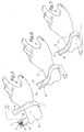
- FIGS. 5 to 7 illustrate the installation of a device 1 around the wrist 27 of a person, such as a skier to whom this device 1 will allow access to ski lifts.
- this device 1 is passed around the wrist 27, as illustrated in FIG. 5.
- the ends 5 and 6 of the strip 4 are applied, one on the other, so that the terminals 11 and 12 are in contact and therefore electrically connected to each other, after which the antenna 3 forms a turn.
- the flaps are then folded down and the fixing tabs 26 are glued to the end 6 of the strip 4, which is symbolized by the arrows F 1 in FIG. 6.
- band 4 forms a bracelet, the passage section is such that it cannot be removed by sliding along hand 28 which extends the wrist 27. This implies that this bracelet must be broken to be removed, which constitutes an obstacle to fraudulent re-use of device 1. In addition, this last hardly likely to be lost after being placed around the wrist 27.
- the position of the device 1 at the level of one of the skier's wrists promotes the establishment of communication required between this device 1 and the device control.
- the device 1 When the tongues 18 and 24 have been partially detached, the device 1 is as illustrated in FIG. 9. The ends 5 and 6 are then separated by exerting on the latter two pulls F 3 and F 4 in opposite directions, which lead tearing of the adhesive sheet 7 and a second rupture of the turn formed by the antenna 3.
- the bracelet formed by the strip 4 When the bracelet formed by the strip 4 is broken ( Figure 10), the device 1 can be removed from the wrist 27.
- the tears of the adhesive sheet 7 at the bridges 25 and the lateral edges of the strip 4 are particularly visible due to the color contrast between the colored face 23 of the adhesive sheet 7 and the rest of this adhesive sheet 7, which facilitates detection by visual inspection of certain fraud attempts.
- the device 1 has the advantage of being inexpensive due to the simplicity of its manufacture and due to the low cost of its components, in particular of the electronic chip 2, which, being provided with a memory not rewritable 8, is much cheaper than chips electronic with rewritable memory currently used.
- the low cost of the device 1 makes the fact possible that this device 1 is intended to serve only one time. Since it is not designed to be reused, the device 1 does not have to be reported to the operator of the ski area to be disconnected after use, such as this is currently the case in ski resorts with remote control devices.
- the code memorized by the electronic chip 2 may not be an access code.
- it can be an identification code of a competitor of a sporting event, in which the passage of this competitor at various points along a route to be traveled is controlled using a device 1.
- each section 9 or 10 of antenna 3 may not consist of a strand metallic, but, for example, consist of a line printed with an appropriate ink.
- the invention is not limited to control in the ski area but can be used in various fields, such as the medical field (automated monitoring of hospitalized patients) or the industrial field (monitoring automated parts in a production.
- the device 1 can be provided to equip not a person but an object such as a suitcase, around the handle of which the strip 4 is mounted by example when this suitcase is checked in before being boarded an airplane.
- a copy of the device 1 can be sent by post to each of the persons arriving at a competition or to each of the persons invited to a reception, at the entrance of which a recording device distance will check the validity of the invitations.
Landscapes
- Engineering & Computer Science (AREA)
- Computer Hardware Design (AREA)
- Microelectronics & Electronic Packaging (AREA)
- Physics & Mathematics (AREA)
- General Physics & Mathematics (AREA)
- Theoretical Computer Science (AREA)
- Selective Calling Equipment (AREA)
Applications Claiming Priority (2)
| Application Number | Priority Date | Filing Date | Title |
|---|---|---|---|
| FR0212727A FR2845803B1 (fr) | 2002-10-14 | 2002-10-14 | Dispositif pour le controle a distance d'un code |
| FR0212727 | 2002-10-14 |
Publications (1)
| Publication Number | Publication Date |
|---|---|
| EP1411468A1 true EP1411468A1 (de) | 2004-04-21 |
Family
ID=32039692
Family Applications (1)
| Application Number | Title | Priority Date | Filing Date |
|---|---|---|---|
| EP03356148A Withdrawn EP1411468A1 (de) | 2002-10-14 | 2003-10-13 | Vorrichtung zur Kontrolle eines Codes auf Entfernung |
Country Status (2)
| Country | Link |
|---|---|
| EP (1) | EP1411468A1 (de) |
| FR (1) | FR2845803B1 (de) |
Cited By (3)
| Publication number | Priority date | Publication date | Assignee | Title |
|---|---|---|---|---|
| FR2908206A1 (fr) * | 2006-11-03 | 2008-05-09 | Oberthur Card Syst Sa | Carte a microcircuit avec antenne deportee |
| ITFO20080026A1 (it) * | 2008-12-15 | 2010-06-16 | Ceracarta S P A | Bracciale sigillo di identificazione e di sicurezza che puo' contenere una serie di informazioni, da applicare a persone animali o cose, e adatto per un uso singolo. |
| ITBO20090329A1 (it) * | 2009-05-21 | 2010-11-22 | Siar S R L | Dispositivo di identificazione a distanza per un alimento |
Families Citing this family (1)
| Publication number | Priority date | Publication date | Assignee | Title |
|---|---|---|---|---|
| FR2873470A1 (fr) * | 2004-07-21 | 2006-01-27 | Fci Sa | Dispositif de connexion pour circuits plats |
Citations (5)
| Publication number | Priority date | Publication date | Assignee | Title |
|---|---|---|---|---|
| EP0125930A2 (de) * | 1983-05-17 | 1984-11-21 | Sinclair Research Limited | Band |
| GB2201266A (en) * | 1986-12-23 | 1988-08-24 | Upperpace Limited | A radio paging watch |
| US5504474A (en) * | 1994-07-18 | 1996-04-02 | Elmo Tech Ltd. | Tag for electronic personnel monitoring |
| GB2355333A (en) * | 1999-07-07 | 2001-04-18 | Neil Welsh | A system for controlling access of individuals to and/or from a restricted area |
| US6431455B1 (en) * | 1998-07-21 | 2002-08-13 | Skidata Ag | Contactless data carrier |
-
2002
- 2002-10-14 FR FR0212727A patent/FR2845803B1/fr not_active Expired - Fee Related
-
2003
- 2003-10-13 EP EP03356148A patent/EP1411468A1/de not_active Withdrawn
Patent Citations (5)
| Publication number | Priority date | Publication date | Assignee | Title |
|---|---|---|---|---|
| EP0125930A2 (de) * | 1983-05-17 | 1984-11-21 | Sinclair Research Limited | Band |
| GB2201266A (en) * | 1986-12-23 | 1988-08-24 | Upperpace Limited | A radio paging watch |
| US5504474A (en) * | 1994-07-18 | 1996-04-02 | Elmo Tech Ltd. | Tag for electronic personnel monitoring |
| US6431455B1 (en) * | 1998-07-21 | 2002-08-13 | Skidata Ag | Contactless data carrier |
| GB2355333A (en) * | 1999-07-07 | 2001-04-18 | Neil Welsh | A system for controlling access of individuals to and/or from a restricted area |
Cited By (4)
| Publication number | Priority date | Publication date | Assignee | Title |
|---|---|---|---|---|
| FR2908206A1 (fr) * | 2006-11-03 | 2008-05-09 | Oberthur Card Syst Sa | Carte a microcircuit avec antenne deportee |
| WO2008059135A1 (fr) * | 2006-11-03 | 2008-05-22 | Oberthur Technologies | Carte à microcircuit avec antenne déportée |
| ITFO20080026A1 (it) * | 2008-12-15 | 2010-06-16 | Ceracarta S P A | Bracciale sigillo di identificazione e di sicurezza che puo' contenere una serie di informazioni, da applicare a persone animali o cose, e adatto per un uso singolo. |
| ITBO20090329A1 (it) * | 2009-05-21 | 2010-11-22 | Siar S R L | Dispositivo di identificazione a distanza per un alimento |
Also Published As
| Publication number | Publication date |
|---|---|
| FR2845803A1 (fr) | 2004-04-16 |
| FR2845803B1 (fr) | 2005-06-17 |
Similar Documents
| Publication | Publication Date | Title |
|---|---|---|
| US7562445B2 (en) | Method of manufacture of an identification wristband construction | |
| EP2087460B1 (de) | Hochfrequenzidentifikationseinrichtung und verfahren zur herstellung der einrichtung | |
| FR2865329A1 (fr) | Dispositif recepteur-emetteur passif alimente par une onde electromagnetique | |
| WO2012019956A1 (fr) | Dispositif d'identification d'un animal et dispositif de fabrication correspondant | |
| FR2821691A1 (fr) | Procede de realisation d'une carte a ci a double interface et carte realisee suivant un tel procede | |
| CA2562587A1 (fr) | Structure comportant un dispositif electronique, notamment pour la fabrication d'un document de securite ou de valeur | |
| EP1692642A1 (de) | Sicherheitsdokument mit einem kontaktlosen chip mit datenmaskierung | |
| EP0692770A1 (de) | Verfahren zur Herstellung einer kontaktlosen Karte durch Umspritzung und so erhaltene kontaktlose Karte | |
| FR2801707A1 (fr) | Procede de fabrication d'une carte a puce hybride contact- sans contact avec un support d'antenne en materiau fibreux | |
| EP0957449A1 (de) | Kontaktlose Speicherkarte, und Herstellungsverfahren einer solchen Karte | |
| EP1442424A1 (de) | Verfahren zur herstellung einer kontaktlosen chipkarte oder einer hybriden chipkarte mit und ohne kontakten mit verbesserter flachheit | |
| WO2006041746A2 (en) | Identification band using serpentine paths to detect tampering | |
| CH619310A5 (en) | Portable card for signal processing system and method of manufacturing this card | |
| FR2880160A1 (fr) | Module electronique double face pour carte a puce hybride | |
| EP2350929B1 (de) | Chipkarte mit einem elektronikmodul, das auf einem kartenkörper getragen wird, das mit einem mittel zum authentifizieren des peering des moduls mit dem körper ausgestattet ist | |
| CA2585335A1 (fr) | Structure comportant un dispositif electronique pour la fabrication d'un document de securite | |
| EP1411468A1 (de) | Vorrichtung zur Kontrolle eines Codes auf Entfernung | |
| US6634563B1 (en) | Non-transferable entitlement identity card | |
| WO2003107266A1 (fr) | Procede de fabrication d'antennes pour transpondeur rfid | |
| WO2017129904A1 (fr) | Procédé de fabrication d'un module de carte à puce et d'une carte à puce | |
| WO1997034249A1 (fr) | Dispositif d'echange d'informations sans contact avec un ticket electronique | |
| CA2646813A1 (fr) | Dispositif radiofrequence | |
| EP2840530A1 (de) | Elektronische Vorrichtung mit Speicher | |
| EP3182507A1 (de) | Einseitiges antennenmodul mit cms-komponenten | |
| FR2916558A1 (fr) | Vignette adhesive souple de securite dotee d'au moins un microcircuit sans contact pour document officiel |
Legal Events
| Date | Code | Title | Description |
|---|---|---|---|
| PUAI | Public reference made under article 153(3) epc to a published international application that has entered the european phase |
Free format text: ORIGINAL CODE: 0009012 |
|
| AK | Designated contracting states |
Kind code of ref document: A1 Designated state(s): AT BE BG CH CY CZ DE DK EE ES FI FR GB GR HU IE IT LI LU MC NL PT RO SE SI SK TR |
|
| AX | Request for extension of the european patent |
Extension state: AL LT LV MK |
|
| 17P | Request for examination filed |
Effective date: 20040910 |
|
| AKX | Designation fees paid |
Designated state(s): AT BE BG CH CY CZ DE DK EE ES FI FR GB GR HU IE IT LI LU MC NL PT RO SE SI SK TR |
|
| STAA | Information on the status of an ep patent application or granted ep patent |
Free format text: STATUS: THE APPLICATION IS DEEMED TO BE WITHDRAWN |
|
| 18D | Application deemed to be withdrawn |
Effective date: 20060503 |