EP1411577B1 - Dispositif pour diagnostiquer l'état de corrosion d'une batterie notamment de véhicule automobile - Google Patents
Dispositif pour diagnostiquer l'état de corrosion d'une batterie notamment de véhicule automobile Download PDFInfo
- Publication number
- EP1411577B1 EP1411577B1 EP03300163A EP03300163A EP1411577B1 EP 1411577 B1 EP1411577 B1 EP 1411577B1 EP 03300163 A EP03300163 A EP 03300163A EP 03300163 A EP03300163 A EP 03300163A EP 1411577 B1 EP1411577 B1 EP 1411577B1
- Authority
- EP
- European Patent Office
- Prior art keywords
- battery
- corrosion
- indicating
- electrodes
- degree
- Prior art date
- Legal status (The legal status is an assumption and is not a legal conclusion. Google has not performed a legal analysis and makes no representation as to the accuracy of the status listed.)
- Expired - Lifetime
Links
Images
Classifications
-
- H—ELECTRICITY
- H01—ELECTRIC ELEMENTS
- H01M—PROCESSES OR MEANS, e.g. BATTERIES, FOR THE DIRECT CONVERSION OF CHEMICAL ENERGY INTO ELECTRICAL ENERGY
- H01M10/00—Secondary cells; Manufacture thereof
- H01M10/06—Lead-acid accumulators
- H01M10/12—Construction or manufacture
-
- H—ELECTRICITY
- H01—ELECTRIC ELEMENTS
- H01M—PROCESSES OR MEANS, e.g. BATTERIES, FOR THE DIRECT CONVERSION OF CHEMICAL ENERGY INTO ELECTRICAL ENERGY
- H01M10/00—Secondary cells; Manufacture thereof
- H01M10/42—Methods or arrangements for servicing or maintenance of secondary cells or secondary half-cells
- H01M10/48—Accumulators combined with arrangements for measuring, testing or indicating the condition of cells, e.g. the level or density of the electrolyte
- H01M10/488—Cells or batteries combined with indicating means for external visualization of the condition, e.g. by change of colour or of light density
-
- H—ELECTRICITY
- H01—ELECTRIC ELEMENTS
- H01M—PROCESSES OR MEANS, e.g. BATTERIES, FOR THE DIRECT CONVERSION OF CHEMICAL ENERGY INTO ELECTRICAL ENERGY
- H01M50/00—Constructional details or processes of manufacture of the non-active parts of electrochemical cells other than fuel cells, e.g. hybrid cells
- H01M50/10—Primary casings; Jackets or wrappings
- H01M50/147—Lids or covers
-
- G—PHYSICS
- G01—MEASURING; TESTING
- G01R—MEASURING ELECTRIC VARIABLES; MEASURING MAGNETIC VARIABLES
- G01R31/00—Arrangements for testing electric properties; Arrangements for locating electric faults; Arrangements for electrical testing characterised by what is being tested not provided for elsewhere
- G01R31/36—Arrangements for testing, measuring or monitoring the electrical condition of accumulators or electric batteries, e.g. capacity or state of charge [SoC]
- G01R31/392—Determining battery ageing or deterioration, e.g. state of health
-
- Y—GENERAL TAGGING OF NEW TECHNOLOGICAL DEVELOPMENTS; GENERAL TAGGING OF CROSS-SECTIONAL TECHNOLOGIES SPANNING OVER SEVERAL SECTIONS OF THE IPC; TECHNICAL SUBJECTS COVERED BY FORMER USPC CROSS-REFERENCE ART COLLECTIONS [XRACs] AND DIGESTS
- Y02—TECHNOLOGIES OR APPLICATIONS FOR MITIGATION OR ADAPTATION AGAINST CLIMATE CHANGE
- Y02E—REDUCTION OF GREENHOUSE GAS [GHG] EMISSIONS, RELATED TO ENERGY GENERATION, TRANSMISSION OR DISTRIBUTION
- Y02E60/00—Enabling technologies; Technologies with a potential or indirect contribution to GHG emissions mitigation
- Y02E60/10—Energy storage using batteries
Definitions
- the present invention relates to a device for diagnosing the state of corrosion of a battery including a motor vehicle.
- a second embodiment comprises a device in which two witnesses are separated. Corrosion of these two witnesses drives their expansion and come into contact to close an alert circuit.
- One of disadvantages of this system is that a complicated device must be implemented to house the two witnesses who will corrode.
- the present invention aims to provide improved means for Reliably diagnose the degree of electrode corrosion of a battery.
- This object of the invention is achieved with a device for diagnosing the state of corrosion of a battery comprising electrodes immersed in an electrolyte, characterized in that said electrical means comprise the control conductor in series, said control conductor being adapted to change a closed electrical circuit in an open electrical circuit when said degree of corrosion exceeds said threshold predetermined.
- the present invention also relates to a battery comprising electrodes immersed in an electrolyte, remarkable in that it is equipped a device in accordance with the foregoing to diagnose the degree of corrosion of parts of some of said electrodes.
- a battery 1 comprising a bundle of electrodes 3 immersed in an electrolyte 5.
- the electrode beam 3 comprises negative electrodes (or cathodes) and positive electrodes (or anodes) sandwiched alternately.
- the cathodes can be formed by lead plates, and the anodes can be formed by metal grids supporting peroxide lead.
- the cathodes and the anodes are connected in series respectively to negative (not shown) and positive 7 terminals fixed on the upper part 8 of the battery 1.
- the electrolyte 5 can be formed by slightly diluted sulfuric acid.
- the chemical equation then governing the discharge of this type of battery called “lead” is then: Pb + PbO 2 + 2H 2 SO 4 ⁇ 2SO 4 Pb + 2H 2 O
- the device according to the invention comprises a control conductive element 9 which constantly quenchs in the part of the electrolyte 5 which is above the electrode beam 3.
- This element control conductor 9 comprises a first conductive terminal 10a which is connected to the positive terminal 7 of the battery 1, and a second conductive terminal 10b which protrudes from the upper portion 8 of the battery 1.
- the conductive control element 9 may be an equivalent alloy wire or similar to that which composes the grids metal anodes.
- FIG. which has been shown in a first state.
- the conductive control element 9 establishes a continuous conductive path and in series between the two conductive terminals 10a and 10b, that is to say a closed electrical circuit.
- the conductive element has a discontinuity, so that it no longer provides a conductive path between the two conductive terminals 10a and 10b, that is to say an open electric circuit.
- the conductive control element 9 is calibrated, that is to say dimensioned to pass from its first state to its second state when its degree of corrosion exceeds a predetermined threshold, corresponding to a degree of corrosion of the grids of the anodes of the battery 1 beyond which it is estimated that the battery must be replaced.
- the device according to the invention also includes electrical means for reporting the degree of corrosion of the conductive control element 9.
- electrical means may comprise a circuit 13 comprising an electroluminescent diode 15, a switch 17 and a resistor 19 interposed between the negative terminal 21 of the battery 1 and the terminal conductor 10b of the control conductive element 9.
- control conductor 9 may allow an electric current to flow between the two conductive terminals 10a and 10b, closed circuit.
- the diode electroluminescent 15 is connected by a conductive path at the same time positive and negative battery 1, so that it turns on.
- the element control conductor 9 does not allow an electrical current to flow between the two conductive terminals 10a and 10b, open circuit. So, in this second state, when the switch 17 is closed, the light-emitting diode 15 is not traversed by no current and remains extinct.
- resistance 19 is to prevent the establishment of a electrolysis current that can flow between the two ends of the element driver 9 once the driver has broken.
- the conductive control element 9 Since the conductive control element 9 is subject rigorously to the the same conditions as the metal grids of the anodes of battery 1, both in which relates to the contact with the electrolyte 5 as regards the temperature (which can be high when the battery is near a motor), you can consider that the degree of corrosion of this control organ gives a faithful image the degree of corrosion of the anodes of the battery 1, and therefore that the device according to the invention offers a quite satisfactory reliability.
- the device according to the invention does not require any measurement of voltage or current across battery, and does not involve any complex means such as a calculator electronic or an external source of alternating current.
- the device according to the invention is therefore simple and inexpensive, which makes it possible to envisage mounting it series on batteries without the need to increase significantly the price of these.
- This device can be easily integrated into the battery cover during its manufacturing. This device is very flexible because it can be used either by the vehicle directly that will simply note the continuity or not of the electrical circuit 13, either by the user who will only have to act on the switch 17 to ensure the state of the battery 1.
Landscapes
- Chemical & Material Sciences (AREA)
- Chemical Kinetics & Catalysis (AREA)
- Electrochemistry (AREA)
- General Chemical & Material Sciences (AREA)
- Engineering & Computer Science (AREA)
- Manufacturing & Machinery (AREA)
- Secondary Cells (AREA)
- Connection Of Batteries Or Terminals (AREA)
Description
- le témoin se corrode jusqu'à ouvrir ledit circuit électrique;
- les moyens électriques comprennent des moyens pour appliquer une tension aux bornes dudit élément conducteur témoin, et pour vérifier si cette tension a pour effet de faire circuler un courant dans ledit élément conducteur témoin;
- les moyens électriques comprennent un circuit destiné à être interposé entre les deux bornes de ladite batterie;
- les moyens électriques comprennent un dispositif d'indication de présence de courant à travers ledit témoin, par exemple une diode électroluminescente;
- le circuit comprend en outre une résistance montée en série avec ledit témoin, ladite résistance étant adaptée d'empêcher l'établissement d'un courant d'électrolyse pouvant circuler après l'ouverture dudit témoin;
- le élément conducteur témoin est formé dans un alliage métallique;
- les moyens électriques comprennent un interrupteur pour initialiser un test de circuit à travers le témoin.
- le dispositif est intégré au couvercle de ladite batterie;
- les certaines électrodes sont des anodes;
- les parties d'électrodes sont des grilles métalliques desdites anodes;
- l'élément conducteur témoin dudit dispositif est directement relié de manière conductrice à la borne positive de ladite batterie.
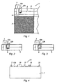
- la figure 1 est une vue partielle en coupe d'une batterie équipée du dispositif selon l'invention,
- la figure 2 est une vue en coupe du dispositif selon l'invention lorsqu'il se trouve dans un premier état correspondant à un degré de corrosion de certaines des électrodes inférieur à un seuil prédéterminé,
- la figure 3 est une vue en coupe du dispositif selon l'invention lorsqu'il se trouve dans un deuxième état correspondant à un degré de corrosion desdites électrodes supérieur à un seuil prédéterminé, et
- la figure 4 est une vue schématique mettant en évidence des moyens électriques de signalement du degré de corrosion desdites électrodes.
Claims (13)
- Dispositif pour diagnostiquer l'état de corrosion d'une batterie (1) comprenant des électrodes (3) immergées dans un électrolyte (5), un élément conducteur témoin (9) destiné à être immergé dans ledit électrolyte (5) et dont le degré de corrosion est représentatif du degré de corrosion de parties de certaines desdites électrodes (3), et des moyens électriques (15, 17, 19) pour signaler quand le degré de corrosion dudit élément conducteur témoin (9) dépasse un seuil prédéterminé correspondant à un degré de corrosion desdites parties au-delà duquel on estime que ladite batterie (1) doit être remplacée, caractérisé en ce que lesdits moyens électriques (15, 17, 19) comprennent le conducteur témoin (9) en série, ledit conducteur témoin étant adapté à changer un circuit électrique fermé en un circuit électrique ouvert quand ledit degré de corrosion dépasse ledit seuil prédéterminé.
- Dispositif selon la revendication 1, caractérisé en ce que ledit témoin (9) se corrode jusqu'à ouvrir ledit circuit électrique.
- Dispositif selon l'une des revendications 1 ou 2, caractérisé en ce que lesdits moyens électriques (15, 17, 19) comprennent des moyens pour appliquer une tension aux bornes dudit élément conducteur témoin (9), et pour vérifier si cette tension a pour effet de faire circuler un courant dans ledit élément conducteur témoin (9).
- Dispositif selon l'une des revendications précédentes, caractérisé en ce que lesdits moyens électriques comprennent un circuit destiné à être interposé entre les deux bornes (7, 8) de ladite batterie (1).
- Dispositif selon l'une des revendications précédentes, caractérisé en ce que lesdits moyens électriques comprennent un dispositif d'indication de présence de courant à travers ledit témoin (9), par exemple une diode électroluminescente (15).
- Dispositif selon la revendications 5, caractérisé en ce que ledit circuit comprend en outre une résistance (19) montée en série avec ledit témoin (9), ladite résistance (19) étant adaptée d'empêcher l'établissement d'un courant d'électrolyse pouvant circuler après l'ouverture dudit témoin (9).
- Dispositif selon l'une des revendications précédentes, caractérisé en ce que ledit élément conducteur témoin (9) est formé dans un alliage métallique.
- Dispositif selon l'une des revendications précédentes, caractérisé en ce que lesdits moyens électriques (15, 17, 19) comprennent un interrupteur (17) pour initialiser un test de circuit à travers le témoin (9).
- Batterie (1) comprenant des électrodes (3) immergées dans un électrolyte (5), caractérisée en ce qu'elle est équipée d'un dispositif conforme à l'une quelconque des revendications précédentes pour diagnostiquer le degré de corrosion de parties de certaines desdites électrodes (3).
- Batterie (1) selon la revendication 9, caractérisée en ce que ledit dispositif est intégré au couvercle de ladite batterie (1).
- Batterie (1) selon l'une des revendications 9 ou 10, caractérisée en ce que lesdites certaines électrodes sont des anodes.
- Batterie (1) selon la revendication 11, caractérisée en ce que lesdites parties d'électrodes sont des grilles métalliques desdites anodes.
- Batterie selon l'une des revendications 9 à 12, caractérisée en ce que l'élément conducteur témoin (9) dudit dispositif est directement relié de manière conductrice à la borne positive (7) de ladite batterie.
Applications Claiming Priority (2)
| Application Number | Priority Date | Filing Date | Title |
|---|---|---|---|
| FR0212871 | 2002-10-16 | ||
| FR0212871A FR2846151B1 (fr) | 2002-10-16 | 2002-10-16 | Dispositif pour diagnostiquer l'etat de corrosion d'une batterie notamment de vehicule automobile |
Publications (2)
| Publication Number | Publication Date |
|---|---|
| EP1411577A1 EP1411577A1 (fr) | 2004-04-21 |
| EP1411577B1 true EP1411577B1 (fr) | 2005-12-28 |
Family
ID=32039772
Family Applications (1)
| Application Number | Title | Priority Date | Filing Date |
|---|---|---|---|
| EP03300163A Expired - Lifetime EP1411577B1 (fr) | 2002-10-16 | 2003-10-16 | Dispositif pour diagnostiquer l'état de corrosion d'une batterie notamment de véhicule automobile |
Country Status (3)
| Country | Link |
|---|---|
| EP (1) | EP1411577B1 (fr) |
| DE (1) | DE60302978T2 (fr) |
| FR (1) | FR2846151B1 (fr) |
Families Citing this family (1)
| Publication number | Priority date | Publication date | Assignee | Title |
|---|---|---|---|---|
| CN113948758B (zh) * | 2021-09-30 | 2023-09-26 | 珠海冠宇电池股份有限公司 | 一种电池及电池的修复方法 |
Family Cites Families (4)
| Publication number | Priority date | Publication date | Assignee | Title |
|---|---|---|---|---|
| US2324424A (en) * | 1939-10-28 | 1943-07-13 | Pollack Paul | Battery protection and indicating system |
| DE3231363A1 (de) * | 1982-08-24 | 1984-03-01 | Varta Batterie Ag, 3000 Hannover | Vorrichtung zum vorzeitigen erkennen des lebensdauer-endes eines bleiakkumulators |
| JPH0821434B2 (ja) * | 1989-12-11 | 1996-03-04 | 新神戸電機株式会社 | 密閉形鉛蓄電池の劣化状態検知方法 |
| DE4215124A1 (de) * | 1992-05-08 | 1993-11-18 | Varta Batterie | Verfahren zur Bestimmung des Ladezustandes einer elektrochemischen Zelle |
-
2002
- 2002-10-16 FR FR0212871A patent/FR2846151B1/fr not_active Expired - Fee Related
-
2003
- 2003-10-16 DE DE60302978T patent/DE60302978T2/de not_active Expired - Lifetime
- 2003-10-16 EP EP03300163A patent/EP1411577B1/fr not_active Expired - Lifetime
Also Published As
| Publication number | Publication date |
|---|---|
| FR2846151B1 (fr) | 2005-02-25 |
| DE60302978D1 (de) | 2006-02-02 |
| DE60302978T2 (de) | 2006-07-27 |
| EP1411577A1 (fr) | 2004-04-21 |
| FR2846151A1 (fr) | 2004-04-23 |
Similar Documents
| Publication | Publication Date | Title |
|---|---|---|
| FR2970602B1 (fr) | Systeme de batterie secondaire et systeme de charge de batterie secondaire | |
| FR2713019A1 (fr) | Procédé et dispositif de surveillance et d'équilibrage dynamique d'un pack de batteries d'accumulateurs. | |
| FR2796205A1 (fr) | Accumulateur electrochimique etanche comportant un dispositif de reprise de courant en aluminium | |
| WO2016207269A1 (fr) | Module de stockage d'énergie électrique | |
| EP2979523B1 (fr) | Module de commande d'un appareil électrique | |
| WO2022023204A1 (fr) | Système de gestion de batteries | |
| FR3041178A1 (fr) | Systeme de batterie avec une protection de surcharge et de sous-charge | |
| EP1368843B1 (fr) | Dispositif de raccordement pour accumulateur electrique | |
| WO2015101465A1 (fr) | Dispositif et procede de detection d'un echauffement d'un ensemble-batterie | |
| EP1411577B1 (fr) | Dispositif pour diagnostiquer l'état de corrosion d'une batterie notamment de véhicule automobile | |
| EP1034592B1 (fr) | Reseau electrique de puissance comprenant un dispositif de precharge et une charge capacitive | |
| EP0910104A1 (fr) | Dispositif de sécurité d'un accumulateur électrochimique | |
| JP2004095361A (ja) | 車両用の電源装置 | |
| FR3121516A1 (fr) | Ensemble de connexion électrique et dispositif d'acquisition de signal de bloc-batterie | |
| FR3120025A1 (fr) | Module d’extension pour une borne de charge CC et borne de charge CC étendue | |
| FR2910723A1 (fr) | Dispositif de securite pour accumulateur etanche. | |
| WO2021074323A1 (fr) | Dispositif de deconnexion et dispositif de mise en court-circuit comprenant un element thermo-activable | |
| EP1411580B1 (fr) | Dispositif pour diagnostiquer l'état de corrosion d'une batterie notamment de véhicule automobile | |
| EP1411581B1 (fr) | Dispositif pour diagnostiquer l'état de corrosion d'une batterie notamment de véhicule automobile | |
| WO2019154818A1 (fr) | Methode et dispositif pour detection de depassement d'un seuil de température prédéfini | |
| FR2992787A3 (fr) | Decharge d'un module batterie | |
| EP4199025B1 (fr) | Dispositif pour mesurer une température et une tension électrique entre deux bornes de raccordement électrique d'un appareil de protection électrique | |
| FR2764391A1 (fr) | Cable de connexion d'alimentation en courant continu fournissant une indication contre les erreurs de branchement | |
| EP3894278B1 (fr) | Dispositif de pre-charge d'un reseau electrique de puissance | |
| FR2575837A1 (fr) | Appareil de controle de la continuite d'un circuit electrique |
Legal Events
| Date | Code | Title | Description |
|---|---|---|---|
| PUAI | Public reference made under article 153(3) epc to a published international application that has entered the european phase |
Free format text: ORIGINAL CODE: 0009012 |
|
| AK | Designated contracting states |
Kind code of ref document: A1 Designated state(s): AT BE BG CH CY CZ DE DK EE ES FI FR GB GR HU IE IT LI LU MC NL PT RO SE SI SK TR |
|
| AX | Request for extension of the european patent |
Extension state: AL LT LV MK |
|
| 17P | Request for examination filed |
Effective date: 20040929 |
|
| AKX | Designation fees paid |
Designated state(s): BE DE ES FR GB IT |
|
| GRAP | Despatch of communication of intention to grant a patent |
Free format text: ORIGINAL CODE: EPIDOSNIGR1 |
|
| GRAS | Grant fee paid |
Free format text: ORIGINAL CODE: EPIDOSNIGR3 |
|
| GRAA | (expected) grant |
Free format text: ORIGINAL CODE: 0009210 |
|
| AK | Designated contracting states |
Kind code of ref document: B1 Designated state(s): BE DE ES FR GB IT |
|
| PG25 | Lapsed in a contracting state [announced via postgrant information from national office to epo] |
Ref country code: IT Free format text: LAPSE BECAUSE OF FAILURE TO SUBMIT A TRANSLATION OF THE DESCRIPTION OR TO PAY THE FEE WITHIN THE PRESCRIBED TIME-LIMIT;WARNING: LAPSES OF ITALIAN PATENTS WITH EFFECTIVE DATE BEFORE 2007 MAY HAVE OCCURRED AT ANY TIME BEFORE 2007. THE CORRECT EFFECTIVE DATE MAY BE DIFFERENT FROM THE ONE RECORDED. Effective date: 20051228 |
|
| REG | Reference to a national code |
Ref country code: GB Ref legal event code: FG4D Free format text: NOT ENGLISH |
|
| REF | Corresponds to: |
Ref document number: 60302978 Country of ref document: DE Date of ref document: 20060202 Kind code of ref document: P |
|
| GBT | Gb: translation of ep patent filed (gb section 77(6)(a)/1977) |
Effective date: 20060227 |
|
| PG25 | Lapsed in a contracting state [announced via postgrant information from national office to epo] |
Ref country code: ES Free format text: LAPSE BECAUSE OF FAILURE TO SUBMIT A TRANSLATION OF THE DESCRIPTION OR TO PAY THE FEE WITHIN THE PRESCRIBED TIME-LIMIT Effective date: 20060408 |
|
| PLBE | No opposition filed within time limit |
Free format text: ORIGINAL CODE: 0009261 |
|
| STAA | Information on the status of an ep patent application or granted ep patent |
Free format text: STATUS: NO OPPOSITION FILED WITHIN TIME LIMIT |
|
| 26N | No opposition filed |
Effective date: 20060929 |
|
| PGFP | Annual fee paid to national office [announced via postgrant information from national office to epo] |
Ref country code: FR Payment date: 20121031 Year of fee payment: 10 Ref country code: DE Payment date: 20121023 Year of fee payment: 10 Ref country code: BE Payment date: 20121022 Year of fee payment: 10 |
|
| PGFP | Annual fee paid to national office [announced via postgrant information from national office to epo] |
Ref country code: GB Payment date: 20121019 Year of fee payment: 10 |
|
| BERE | Be: lapsed |
Owner name: *RENAULT S.A.S. Effective date: 20131031 |
|
| GBPC | Gb: european patent ceased through non-payment of renewal fee |
Effective date: 20131016 |
|
| REG | Reference to a national code |
Ref country code: DE Ref legal event code: R119 Ref document number: 60302978 Country of ref document: DE Effective date: 20140501 |
|
| PG25 | Lapsed in a contracting state [announced via postgrant information from national office to epo] |
Ref country code: GB Free format text: LAPSE BECAUSE OF NON-PAYMENT OF DUE FEES Effective date: 20131016 |
|
| REG | Reference to a national code |
Ref country code: FR Ref legal event code: ST Effective date: 20140630 |
|
| PG25 | Lapsed in a contracting state [announced via postgrant information from national office to epo] |
Ref country code: DE Free format text: LAPSE BECAUSE OF NON-PAYMENT OF DUE FEES Effective date: 20140501 Ref country code: FR Free format text: LAPSE BECAUSE OF NON-PAYMENT OF DUE FEES Effective date: 20131031 |
|
| PG25 | Lapsed in a contracting state [announced via postgrant information from national office to epo] |
Ref country code: BE Free format text: LAPSE BECAUSE OF NON-PAYMENT OF DUE FEES Effective date: 20131031 |