EP1412213B1 - Kabriolett mit versenkbarem dach - Google Patents
Kabriolett mit versenkbarem dach Download PDFInfo
- Publication number
- EP1412213B1 EP1412213B1 EP02794617A EP02794617A EP1412213B1 EP 1412213 B1 EP1412213 B1 EP 1412213B1 EP 02794617 A EP02794617 A EP 02794617A EP 02794617 A EP02794617 A EP 02794617A EP 1412213 B1 EP1412213 B1 EP 1412213B1
- Authority
- EP
- European Patent Office
- Prior art keywords
- vehicle
- roof portion
- roof
- transverse
- boot
- Prior art date
- Legal status (The legal status is an assumption and is not a legal conclusion. Google has not performed a legal analysis and makes no representation as to the accuracy of the status listed.)
- Expired - Lifetime
Links
Images


Classifications
-
- B—PERFORMING OPERATIONS; TRANSPORTING
- B60—VEHICLES IN GENERAL
- B60J—WINDOWS, WINDSCREENS, NON-FIXED ROOFS, DOORS, OR SIMILAR DEVICES FOR VEHICLES; REMOVABLE EXTERNAL PROTECTIVE COVERINGS SPECIALLY ADAPTED FOR VEHICLES
- B60J7/00—Non-fixed roofs; Roofs with movable panels, e.g. rotary sunroofs
- B60J7/20—Vehicle storage compartments for roof parts or for collapsible flexible tops
- B60J7/207—Vehicle storage compartments for roof parts or for collapsible flexible tops being adjustable in volume, i.e. collapsible in order to increase luggage space in boot when roof is not stored
-
- B—PERFORMING OPERATIONS; TRANSPORTING
- B60—VEHICLES IN GENERAL
- B60J—WINDOWS, WINDSCREENS, NON-FIXED ROOFS, DOORS, OR SIMILAR DEVICES FOR VEHICLES; REMOVABLE EXTERNAL PROTECTIVE COVERINGS SPECIALLY ADAPTED FOR VEHICLES
- B60J7/00—Non-fixed roofs; Roofs with movable panels, e.g. rotary sunroofs
- B60J7/08—Non-fixed roofs; Roofs with movable panels, e.g. rotary sunroofs of non-sliding type, i.e. movable or removable roofs or panels, e.g. let-down tops or roofs capable of being easily detached or of assuming a collapsed or inoperative position
- B60J7/12—Non-fixed roofs; Roofs with movable panels, e.g. rotary sunroofs of non-sliding type, i.e. movable or removable roofs or panels, e.g. let-down tops or roofs capable of being easily detached or of assuming a collapsed or inoperative position foldable; Tensioning mechanisms therefor, e.g. struts
- B60J7/14—Non-fixed roofs; Roofs with movable panels, e.g. rotary sunroofs of non-sliding type, i.e. movable or removable roofs or panels, e.g. let-down tops or roofs capable of being easily detached or of assuming a collapsed or inoperative position foldable; Tensioning mechanisms therefor, e.g. struts with a plurality of rigid plate-like elements or rigid non plate-like elements, e.g. with non-slidable, but pivotable or foldable movement
- B60J7/143—Non-fixed roofs; Roofs with movable panels, e.g. rotary sunroofs of non-sliding type, i.e. movable or removable roofs or panels, e.g. let-down tops or roofs capable of being easily detached or of assuming a collapsed or inoperative position foldable; Tensioning mechanisms therefor, e.g. struts with a plurality of rigid plate-like elements or rigid non plate-like elements, e.g. with non-slidable, but pivotable or foldable movement for covering the passenger compartment
- B60J7/148—Non-fixed roofs; Roofs with movable panels, e.g. rotary sunroofs of non-sliding type, i.e. movable or removable roofs or panels, e.g. let-down tops or roofs capable of being easily detached or of assuming a collapsed or inoperative position foldable; Tensioning mechanisms therefor, e.g. struts with a plurality of rigid plate-like elements or rigid non plate-like elements, e.g. with non-slidable, but pivotable or foldable movement for covering the passenger compartment at least one element being stored in vertical fashion
-
- B—PERFORMING OPERATIONS; TRANSPORTING
- B60—VEHICLES IN GENERAL
- B60J—WINDOWS, WINDSCREENS, NON-FIXED ROOFS, DOORS, OR SIMILAR DEVICES FOR VEHICLES; REMOVABLE EXTERNAL PROTECTIVE COVERINGS SPECIALLY ADAPTED FOR VEHICLES
- B60J7/00—Non-fixed roofs; Roofs with movable panels, e.g. rotary sunroofs
- B60J7/20—Vehicle storage compartments for roof parts or for collapsible flexible tops
- B60J7/201—Vehicle storage compartments for roof parts or for collapsible flexible tops being outside of vehicle, e.g. onto boot lid, or into a storage compartment to be closed by one of the roof panels itself
Definitions
- the present invention relates to a convertible vehicle having a folding hard roof which can be placed in the folded position inside the trunk of said vehicle.
- a foldable hard top convertible vehicle comprising at least a front roof portion and a rear roof portion, the rear roof portion being pivotally mounted about a transverse pivot axis on the vehicle body, the roof portion.
- front being pivotally mounted on each side of the vehicle at one end of a lever arm articulated at its other end to the vehicle body, and being at its articulated rear end at the front end of the rear roof portion, so that, in the folded position of the roof in the trunk of the vehicle, the front roof portion is in a substantially horizontal position above the rear roof portion, the vehicle having in the upper front of the trunk a upper transverse stiffening beam to stiffen the bodywork.
- Such a vehicle is known in particular from DE-A-19 834 850.
- the rear roof portion In the folded position of such a foldable roof in the rear trunk of the vehicle, the rear roof portion has its concavity turned upward while the front roof portion has its concavity turned downwards, so that these two parts occupy a large volume inside the trunk which includes only a very limited volume reserved for luggage.
- the object of the present invention is to overcome the above drawbacks of such a rigid roof folding vehicle, and to propose a roofed vehicle rigid folding of the aforementioned type whose roof in the folded position occupies a small volume at the rear of the vehicle to leave as large a volume as possible available to users of the vehicle, for example to allow the development a volume accessible from inside the vehicle.
- the vehicle comprises a bottom wall having in longitudinal section a general shape of C, located in front of said first curved front surface, and extending from said lower region before, first towards the rear, then upwards, then at least partially forwards to support an upper transverse stiffening beam located in a front upper part of the rear trunk, the bottom wall extending between two side walls to which it is fixed to form a receptacle delimiting towards the bottom and towards the rear, on the one hand, laterally, on the other hand, a first useful central volume forming part of said first central volume before.
- This receptacle delimits a first useful central volume perfectly isolated from the roof in the folded position and the spaces traveled by the rear roof portion during the movements of the rear roof between its deployed position, above the passenger compartment of the vehicle, and its folded position inside the trunk.
- This first useful central volume can therefore contain delicate objects such as clothing, small luggage, and can be easily accessible from the passenger compartment, either from above or from the front by folding forward the folder of at least a seat whose rear wall forms said receptacle.
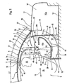
- the folding hard roof 1 for a convertible vehicle 2 comprises a front roof portion 3 and a rear roof portion 4.
- the rear roof portion 4 is pivotally mounted on the body 6 of the vehicle at two opposite points transversely located on the same transverse axis of pivoting 5.
- the front roof portion 3 is pivotally mounted on each side of the vehicle at a hinge point 7a at a first end 7 d ' a lever arm 8 articulated at its other end 9 at a point of articulation 9a on the bodywork 6 of the vehicle 2.
- the front roof portion 3 is at its rear end articulated to the front end 11 of the rear roof portion 4.
- the two lever arms 8 and the rear roof portion 4, which are hinged to the bodywork 6 of the vehicle, constitute with the latter and the front roof portion 3 a deformable quadrilateral which maintains the front roof portion 3 substantially horizontal when pivoting the roof 1 in one direction or the other, its concavity remaining facing downwards.
- the front roof portion 3 is in a substantially horizontal position above the rear roof portion 4.
- the vehicle 2 further comprises, in the upper upper region 48 of the rear trunk 16, an upper transverse stiffening beam, schematized at 50, to stiffen the bodywork 6 of the vehicle 2 to the right of this region 48.
- the upper transverse beam 50 a any suitable shape and structure.
- the rear roof portion 4 occupies in the trunk 16 of the vehicle a predetermined inclined position using the maximum available height between the bottom 14 and the cover 17 of the trunk 16 all being as far as possible to the aforesaid region 13 at the bottom and front of said trunk 16.
- the length L1 in the longitudinal direction of the vehicle 2 represented by the arrow 12, of the rear roof portion 4 is significantly greater than the length L2 of the front roof portion 3.
- These lengths L1 and L2 can be curved lengths, as shown in Figure 1. They could of course be straight lengths obtained by projection of the aforementioned curved lengths on an axis parallel to the longitudinal direction 12 of the vehicle
- transverse pivot axis 5 of the rear roof portion 4 is disposed on the bodywork 6 of the vehicle in a predetermined manner depending on the length L1 of the rear roof portion 4 and depending on the position of the rear roof portion 4.
- backrest 41 whose rear surface 15 constitutes the front wall 15 which limits forward the space available in the trunk 16 of the vehicle.
- the rear roof portion 4 occupies an inclined position starting from the lower front region 13 located at the bottom 14 of the trunk 16 at the front of said trunk 16, and extending substantially backwards and upwards.
- the rear roof portion 4 sweeps during its pivoting a volume V3 between a first curved surface before 18 and a second curved rear surface 19 which respectively limit in the passenger compartment and in the trunk, forward of the front surface 18, a first central volume before V1 can be accessible from inside the vehicle, and at the rear of the rear surface 19, a second rear volume V2 can be accessible from the outside from the rear of the vehicle.
- the first curved surface before 18 is the surface generated by the cross section of the rear roof portion 4 at the point 20 of said rear roof portion located at the shortest distance from the axis of the rear roof portion. transverse pivoting 5 of said rear roof portion 4.
- the first curved front surface 18 intersects the vertical longitudinal plane of symmetry of the vehicle, which is the plane of FIGS. 1 to 4, according to the circle 21, of radius R1, generated by the point 20 during the pivoting of the rear roof portion 4 in one direction or the other around the axis 5.
- the first curved front surface 18 has a central portion generated by the substantially flat central portion of the rear roof portion 4, and two side portions generated by the relatively small radius side portions of said rear roof portion 4.
- the second rear curved surface 19 is generated by the rear edge 22 of the rear roof portion 4 and intersects the vertical longitudinal symmetry plane, which is the plane of FIGS. 1 to 4, along the circle 23, of radius R2, generated by the midpoint 24 of said rear edge 22.
- the first central volume V1 can extend transversely over a large part of the width of the passenger compartment of the vehicle, with the exception of the areas close to the side walls of said passenger compartment. (See Figures 6 and 7).
- the upper end of the bottom wall 26 is extended at least partially forwards by a portion of substantially complementary horizontal wall, schematized at 26c, adapted to isolate the useful volume V1a from the rear of the vehicle, and to bear on the upper transverse stiffening beam 50.
- the front roof portion 3 covers, in its folded position, a rear portion of the useful central volume V1a whose front remains free for easy access and amenities complementary.
- the vehicle 2 comprises a bottom wall 26 having in longitudinal section a general shape of C, situated in front of said first curved surface before 18, and extending from said lower region before 13, first towards the rear, then upwards, then at least partially towards the front until bearing on said upper stiffening beam before 50, according to three successive sections respectively lower 26a, rear 26b and upper 26c wall 26 opening towards the front.
- the bottom wall 26 extends between two side walls 27 to which it is fixed to form a receptacle 51 accessible from the passenger compartment 25 and delimiting respectively towards the bottom and towards the rear, on the one hand, laterally, on the other side on the one hand, the first useful central volume V1a forming part of said first central volume V1.
- the upper front stiffening beam 50 which has any suitable shape and structure, cooperates with any suitable structural means of the bodywork 6 respectively constituting a front lower transverse stiffening beam, schematized in FIG. 52, and two lateral stiffening posts, schematized at 53, to form a stiffening assembly of the bodywork 6 in the form of a quadrilateral 57.
- the walls 26 and 27 of the receptacle 51 are respectively fixed to the upper beam 50 and the lower beam 52 and participate in communicating to the quadrilateral 57 and the bodywork 6 of the vehicle a high rigidity and a resistance to deformation and torsion much sought after. in discoverable vehicles.
- the bottom wall 26 is fixed in any way at least on the lower face 50a of the upper beam 50 and at least on the upper face 52a of the lower beam. 52.
- means 28 forming roll bar are placed immediately in front of the location occupied by the front roof portion 3 in its folded position inside the trunk 16 of the vehicle and are fixed to the beam of upper transverse stiffening 50 (see FIGS. 1, 3 and 4)
- These means forming a roll bar are any known means, and may be constituted, for example, either by a single arch, or by two arches located respectively behind each of the passenger seats, these arches may be fixed or deformable.
- Access to the interior of the receptacle 51 is also possible from the front, for example by folding forward the backrest 41 of at least one of the seats in front of the trunk 16.
- the vehicle 2 comprises a transverse panel, schematized at 31, limiting forwardly a second useful rear volume V2a available to receive luggage inside the trunk 16 and forming part of the second volume V2.
- the transverse panel 31 is preferably movable between a first position forward, shown schematically in Figures 1 and 2, when the folding roof 1 is in its deployed position above the passenger compartment 25, and a second position to the rear, schematically in Figures 1, 3 and 4, when the roof 1 is in its folded position inside the trunk 16.
- the transverse panel 31 is pivotally mounted about a second transverse pivot axis 32 located near the bottom 14 of the rear trunk 16, for example on a transverse support 33 fixed to the bottom 14 behind the second curved rear surface 19.
- the panel 31 has in its forward position a position close to the vertical and substantially tangential from the rear to the wall 26, and in its rear position an inclined position as close as possible to the two front roof portions. 3 and back 4 in their folded position.
- the vehicle 2 comprises complementary locking means schematized at 54 and 55 and carried respectively by the panel 31 and the body 6 to lock the transverse panel 31 to the bodywork 6 of the vehicle and the immobilize in the first position forward and in the second position towards the rear of said panel 31.
- locking means 54 and 55 are any known means, and are for example constituted by movable fingers 54 or 55 adapted to cooperate with corresponding lugs 55 or 54.
- the vehicle 2 comprises sensors schematized at 56 and adapted to detect the presence of the transverse panel 31 in its first position or in its second position.
- Such sensors 56 are integrated in a logic circuit for controlling the successive movements of the cover 17, the shelf 34, the panel 31 and the roof elements 3 and 4, so as to confirm or denying an order of movement of the roof elements 3 and 4 in one direction or the other if the other movable members are or are not in the correct position.
- FIGS that the vehicle 2 comprises a tablet 34 movable between a substantially horizontal normal position, shown schematically in Figures 1 and 2, and a substantially vertical raised position, shown schematically in Figures 1 and 3, and allowing the pivoting of the folding roof 1 in one way or the other, as schematized by the arrow 35.
- the tablet 34 could for example be pivotally mounted around lateral pivot points located on the same third transverse pivot axis 40.
- the shelf 34 could be pivotally mounted on two pivoting arms disposed on each side of the vehicle (not shown).
- the system 1 comprises, at the front of the hood 17 of the rear trunk 16, a transverse flap 36 adapted to pivot from front to rear, as shown schematically by the arrow 37, to pass the front end 11 of the rear roof portion 4 and the rear end 10 of the front roof portion 3. This flap is then closed.
- the cover 58 of the trunk is in one piece, and the vehicle comprises means for opening the cover 58 of the rear to the front, in its position 58a, for the loading of luggage, or the front to the rear, in its position 58b, for the passage of roof 1 folded towards the trunk 16.
- the rear roof portion 4 carries on each side of the vehicle a fixed side window 38 that can pivot with said rear roof portion 4.
- Such a window 38 thus makes it possible to increase the lateral glazed area of the vehicle, without the disadvantage encountered in the folding roofs of the prior art, in which such panes must be vertically movable and be lowered before turning the roof over. to its folded position, and then raised after pivoting the folding roof to its deployed position.
- each lever arm 8 on the bodywork 6 of the vehicle 2 is located behind the transverse pivot axis 5 of the rear roof portion 4.
- the articulation point 7a of each lever arm 8 on the rear end 10 of the front roof part 3 is located, in the deployed position of the roof system 1, behind the articulation points 42 of the part of front roof 3 at the front end 11 of the rear roof portion 4.
- each lever 8 is carried by a corresponding first tab 43 extending rearwardly from the rear end 10 of the front roof portion 3.
- each hinge point 42 is carried by a corresponding second tab 44 extending forwards from the front end 11 of the rear roof portion 4.
Landscapes
- Engineering & Computer Science (AREA)
- Mechanical Engineering (AREA)
- Body Structure For Vehicles (AREA)
- Vehicle Step Arrangements And Article Storage (AREA)
Claims (11)
- Kabriolett (2) mit versenkbarem, starren Dach (1), wobei das Fahrzeug (2) ein vorderes Dachteil (3) und ein hinteres Dachteil (4) aufweist, wobei das hintere Dachteil (4) an der Karosserie (6) des Fahrzeugs (2) entlang einer quer verlaufenden Schwenkachse (5) verschwenkbar gelagert ist, wobei das vordere Dachteil (3) auf jeder Seite des Fahrzeugs (2) an einem Ende (7) eines Hebelarms (8) verschwenkbar gelagert ist, der mit seinem anderen Ende (9) an der Karosserie (6) des Fahrzeugs angelenkt ist, und mit seinem hinteren Ende (10) am vorderen Ende (11) des hinteren Dachteils (4) angelenkt ist, so dass in versenkter Stellung der Dacheinrichtung (1) in einem heckseitigen Kasten (16) des Fahrzeugs (2) das vordere Dachteil (3) sich in einer im wesentlichen horizontalen Stellung oberhalb des hinteren Dachteils (4) befindet, wobei die Länge (L1) in Längsrichtung (12) des hinteren Dachteils (4) derart ausgeprägt größer ist als die (L2) des vorderen Dachteils (3) und die quer verlaufende Schwenkachse (5) des hinteren Dachteils (4) derart angeordnet ist, dass in seiner im heckseitigen Kasten (16) des Fahrzeugs (2) versenkten Stellung das hintere Dachteil (4) eine geneigte Stellung ausgehend von dem unteren Vorderbereich (13) in Höhe des Bodens (14) des heckseitigen Kastens (16) vor dem Kasten einnimmt und im wesentlichen nach hinten und nach oben verläuft, wobei das hintere Dachteil (4) während seiner Schwenkbewegung einen Raum (V3) überstreicht, der zwischen einer ersten, vorderen Kurvenfläche (18) und einer zweiten, hinteren Kurvenfläche (19) vorhanden ist, welche im Fahrgastraum (25) bzw. im heckseitigen Kasten (16) einen ersten, vorderen Mittelraum (V1) begrenzen, der vom Inneren des Fahrzeugs (2) aus zugänglich sein kann, sowie einen zweiten, hinteren Raum (V2), der von außerhalb vom Heck des Fahrzeugs (2) aus zugänglich sein kann, dadurch gekennzeichnet, dass das Fahrzeug eine im Längsschnitt insgesamt C-förmige Bodenwand (26) aufweist, die sich vor der ersten, vorderen Kurvenfläche (18) befindet, und sich von dem unteren Vorderbereich (13) zunächst nach hinten, dann nach oben, dann zumindest teilweise nach vorne erstreckt, bis sie an einen oberen, quer verlaufenden Versteifungsbalken (50) in Anlage gelangt, der sich in einem oberen, vorderen Teil des heckseitigen Kastens (16) befindet, wobei die Bodenwand (26) sich zwischen zwei Seitenwänden (27) erstreckt, an denen sie befestigt ist, um einen Behälter (51) zu bilden, der einerseits zum Boden und zur Heckseite hin und andererseits seitlich einen ersten mittleren Nutzraum (V1a) begrenzt, der zu dem ersten Mittelraum (V1) gehört.
- Fahrzeug mit versenkbarem, starren Dach nach Anspruch 1, dadurch gekennzeichnet, dass Mittel zum Bilden eines Überrollbügels (28) unmittelbar vor der Stelle positioniert sind, die von dem vorderen Dachteil (3) in seiner versenkten Stellung im heckseitigen Kasten (16) des Fahrzeugs eingenommen wird, und an dem oberen Versteifungsbalken (50) befestigt sind.
- Fahrzeug mit versenkbarem, starren Dach nach einem der vorangehenden Ansprüche, dadurch gekennzeichnet, dass es eine Querplatte (31) aufweist, die nach vorne einen zweiten, hinteren Nutzraum (V2a) begrenzt, der zum Verstauen von Gepäck im Inneren des heckseitigen Kastens (16) zur Verfügung steht und zum zweiten, hinteren Raum (V2) gehört, wobei die Querplatte (31) vorzugsweise zwischen einer ersten Stellung nach vorne beweglich ist, wenn das versenkbare Dach (1) sich in seiner über den Fahrgastraum (25) ausgefahrenen Stellung befindet, und einer zweiten Stellung nach hinten beweglich ist, wenn das Dach (1) sich in seiner versenkten Stellung im heckseitigen Kasten (16) des Fahrzeugs (2) befindet.
- Fahrzeug mit versenkbarem, starren Dach nach Anspruch 3, dadurch gekennzeichnet, dass die Querplatte (31) um eine quer verlaufende Schwenkachse (32) herum verschwenkbar gelagert ist, die sich in der Nähe des Bodens (14) des heckseitigen Kastens (16) befindet.
- Fahrzeug mit versenkbarem, starren Dach nach Anspruch 3 oder 4, dadurch gekennzeichnet, dass es Verriegelungsmittel (54, 55) zum Verriegeln der Querplatte (31) mit der Fahrzeugkarosserie in einer ersten Stellung zur Vorderseite und in der zweiten Stellung zur Rückseite der Platte (31) hin aufweist.
- Fahrzeug mit versenkbarem, starren Dach nach einem der Ansprüche 3 bis 5, dadurch gekennzeichnet, dass es Sensoren (56) aufweist, die darauf abgestimmt sind, das Vorhandensein der Querplatte (31) in ihrer ersten Stellung bzw. in ihrer zweiten Stellung zu erfassen.
- Fahrzeug mit versenkbarem, starren Dach nach einem der vorangehenden Ansprüche, dadurch gekennzeichnet, dass das hintere Dachteil (4) auf jeder Seite eine feste hintere Seitenfensterscheibe (38) trägt.
- Fahrzeug mit versenkbarem, starren Dach nach einem der vorangehenden Ansprüche, dadurch gekennzeichnet, dass es eine Abdeckung (34) aufweist, die zwischen einer im wesentlichen horizontalen, normalen Stellung und einer im wesentlichen senkrechten, angehobenen Stellung beweglich ist, wodurch das Verschwenken des versenkbaren Dachs (1) in der einen oder anderen Richtung möglich ist.
- Fahrzeug mit versenkbarem, starren Dach nach einem der vorangehenden Ansprüche, dadurch gekennzeichnet, dass der Anlenkpunkt (9a) eines jeden Hebelarms (8) an der Karosserie (6) des Fahrzeugs (2) sich hinter der quer verlaufenden Schwenkachse (5) des hinteren Dachteils (4) befindet und dass in der ausgefahrenen Stellung des Dachs (1) der Anlenkpunkt (7a) eines jeden Hebelarms (8) an dem hinteren Ende (10) des vorderen Dachteils (3) sich hinter den Anlenkpunkten (42) des vorderen Dachteils (3) an dem vorderen Ende (11) des hinteren Dachteils (4) befindet.
- Fahrzeug mit versenkbarem, starren Dach nach einem der vorangehenden Ansprüche, dadurch gekennzeichnet, dass es vor der Abdeckhaube (17) des heckseitigen Kastens (16) eine quer verlaufende Klappe (36) aufweist, die darauf abgestimmt ist, von vorne nach hinten zu schwenken, um das Verschwenken des versenkbaren, starren Dachs (1) in der einen oder anderen Richtung zu gestatten.
- Fahrzeug mit versenkbarem, starren Dach nach einem der Ansprüche 1 bis 9, dadurch gekennzeichnet, dass die Abdeckhaube (58) des heckseitigen Kastens (16) aus einem Teil besteht und dass das Fahrzeug (2) Mittel zum Öffnen der Haube (58) von hinten nach vorne zum Einladen von Gepäckstücken bzw. von vorne nach hinten zum Überführen des versenkbaren Dachs in den Kofferraum (16) aufweist.
Applications Claiming Priority (3)
| Application Number | Priority Date | Filing Date | Title |
|---|---|---|---|
| FR0110348A FR2828137B1 (fr) | 2001-08-01 | 2001-08-01 | Systeme de toit rigide retractable pour vehicule automobile |
| FR0110348 | 2001-08-01 | ||
| PCT/FR2002/002766 WO2003013889A1 (fr) | 2001-08-01 | 2002-07-31 | Vehicule decouvrable a toit repliable |
Publications (2)
| Publication Number | Publication Date |
|---|---|
| EP1412213A1 EP1412213A1 (de) | 2004-04-28 |
| EP1412213B1 true EP1412213B1 (de) | 2006-04-05 |
Family
ID=8866203
Family Applications (1)
| Application Number | Title | Priority Date | Filing Date |
|---|---|---|---|
| EP02794617A Expired - Lifetime EP1412213B1 (de) | 2001-08-01 | 2002-07-31 | Kabriolett mit versenkbarem dach |
Country Status (7)
| Country | Link |
|---|---|
| US (1) | US6866323B2 (de) |
| EP (1) | EP1412213B1 (de) |
| JP (1) | JP4150338B2 (de) |
| DE (1) | DE60210468T2 (de) |
| ES (1) | ES2261775T3 (de) |
| FR (1) | FR2828137B1 (de) |
| WO (1) | WO2003013889A1 (de) |
Cited By (1)
| Publication number | Priority date | Publication date | Assignee | Title |
|---|---|---|---|---|
| DE102015220442A1 (de) * | 2015-10-20 | 2017-04-20 | Magna Car Top Systems Gmbh | Verfahren zum Ablegen einer Seitenscheibe eines Cabriolet-Fahrzeugs |
Families Citing this family (12)
| Publication number | Priority date | Publication date | Assignee | Title |
|---|---|---|---|---|
| DE10248759B4 (de) * | 2002-10-18 | 2005-03-24 | Wilhelm Karmann Gmbh | Kraftfahrzeug mit einem fahrbaren Verdeck |
| FR2851746B1 (fr) | 2003-02-28 | 2005-04-08 | Toit escamotable de vehicule | |
| DE10331848B4 (de) * | 2003-07-14 | 2015-01-22 | GM Global Technology Operations LLC (n. d. Ges. d. Staates Delaware) | Kraftfahrzeugkarosserie mit Faltdach |
| FR2873630B1 (fr) * | 2004-07-28 | 2006-11-17 | Peugeot Citroen Automobiles Sa | Structure de coffre de vehicule automobile equipe d'une telle structure de coffre |
| FR2880589B1 (fr) * | 2005-01-07 | 2007-02-23 | Heuliez Sa | Vehicule comprenant un element de toit arriere rapporte sur le capot du coffre |
| DE102005009720A1 (de) * | 2005-03-03 | 2006-09-07 | Daimlerchrysler Ag | Verdeck für ein Cabriolet-Fahrzeug |
| DE102006042285B4 (de) * | 2006-09-08 | 2018-12-27 | Dr. Ing. H.C. F. Porsche Aktiengesellschaft | Anordnung eines Verdeckkastendeckels an einem Kraftfahrzeug |
| DE102006042294A1 (de) * | 2006-09-08 | 2008-03-27 | Dr.Ing.H.C. F. Porsche Ag | Bewegliches Fahrzeugdach |
| US7665799B1 (en) | 2006-09-15 | 2010-02-23 | Appropriate Combined Technologies, Llc | Truck bed extension and roll bar apparatus |
| EP2614734A1 (de) | 2012-01-10 | 2013-07-17 | Manufactures Industrials de Tortella, SA | Flammenhemmender, wasserdichter, dehnbarer natürlicher Stoff und Kissen- oder Matratzenschutz/-hülle mit dem besagten Stoff |
| DE102014014090A1 (de) * | 2014-09-23 | 2016-03-24 | Audi Ag | Vorrichtung zur Aufnahme eines Verdecks eines Kraftfahrzeugs in Cabriolet-Bauform und Kraftfahrzeug |
| JP7167483B2 (ja) * | 2018-05-15 | 2022-11-09 | 大同特殊鋼株式会社 | ダイカスト金型用鋼及びダイカスト金型 |
Family Cites Families (11)
| Publication number | Priority date | Publication date | Assignee | Title |
|---|---|---|---|---|
| IT1278123B1 (it) * | 1994-07-08 | 1997-11-17 | Daimler Benz Ag | Autoveicolo con tettuccio almeno parzialmente abbassabile. |
| DE4431656C1 (de) * | 1994-09-06 | 1995-12-07 | Daimler Benz Ag | Stauraumanordnung für das Klappdach von Fahrzeugen |
| DE19712967A1 (de) * | 1997-03-27 | 1998-10-01 | Bayerische Motoren Werke Ag | Deckelanordnung für den Verdeckkasten eines Cabriolets |
| DE19834850B4 (de) * | 1998-08-01 | 2004-09-23 | Daimlerchrysler Ag | Kraftfahrzeug mit versenkbarem Verdecksystem |
| ATE227658T1 (de) * | 1999-10-12 | 2002-11-15 | Dura Convertible Systems Gmbh | Versenkbares hardtop für kraftfahrzeuge sowie kraftfahrzeug mit hardtop |
| DE10111207A1 (de) * | 2001-03-08 | 2002-09-19 | Valmet Automotive Oy Uusikaupu | Verdeck eines Kabrioletts |
| JP3524524B2 (ja) * | 2001-07-10 | 2004-05-10 | 本田技研工業株式会社 | コンバーチブルハードトップの格納構造 |
| US6767044B2 (en) * | 2001-08-27 | 2004-07-27 | Mazda Motor Corporation | Roof construction for an automotive vehicle |
| DE10205342B4 (de) * | 2002-02-08 | 2004-12-23 | Webasto Vehicle Systems International Gmbh | Cabriolet-Kraftfahrzeug mit klappbarem Hardtop |
| JP3885607B2 (ja) * | 2002-02-25 | 2007-02-21 | マツダ株式会社 | 車両のルーフ構造 |
| DE10231838B4 (de) * | 2002-07-12 | 2004-12-16 | Webasto Vehicle Systems International Gmbh | Versenkbares Fahrzeugdach |
-
2001
- 2001-08-01 FR FR0110348A patent/FR2828137B1/fr not_active Expired - Fee Related
-
2002
- 2002-07-31 US US10/485,235 patent/US6866323B2/en not_active Expired - Fee Related
- 2002-07-31 EP EP02794617A patent/EP1412213B1/de not_active Expired - Lifetime
- 2002-07-31 JP JP2003518856A patent/JP4150338B2/ja not_active Expired - Fee Related
- 2002-07-31 DE DE60210468T patent/DE60210468T2/de not_active Expired - Lifetime
- 2002-07-31 WO PCT/FR2002/002766 patent/WO2003013889A1/fr not_active Ceased
- 2002-07-31 ES ES02794617T patent/ES2261775T3/es not_active Expired - Lifetime
Cited By (2)
| Publication number | Priority date | Publication date | Assignee | Title |
|---|---|---|---|---|
| DE102015220442A1 (de) * | 2015-10-20 | 2017-04-20 | Magna Car Top Systems Gmbh | Verfahren zum Ablegen einer Seitenscheibe eines Cabriolet-Fahrzeugs |
| DE102015220442B4 (de) * | 2015-10-20 | 2019-03-21 | Magna Car Top Systems Gmbh | Verfahren zum Ablegen einer Seitenscheibe eines Cabriolet-Fahrzeugs |
Also Published As
| Publication number | Publication date |
|---|---|
| DE60210468T2 (de) | 2006-11-16 |
| JP2004537456A (ja) | 2004-12-16 |
| DE60210468D1 (de) | 2006-05-18 |
| JP4150338B2 (ja) | 2008-09-17 |
| FR2828137A1 (fr) | 2003-02-07 |
| US6866323B2 (en) | 2005-03-15 |
| FR2828137B1 (fr) | 2004-03-26 |
| EP1412213A1 (de) | 2004-04-28 |
| ES2261775T3 (es) | 2006-11-16 |
| WO2003013889A1 (fr) | 2003-02-20 |
| US20040212213A1 (en) | 2004-10-28 |
| WO2003013889A9 (fr) | 2004-04-15 |
Similar Documents
| Publication | Publication Date | Title |
|---|---|---|
| EP1215107B1 (de) | Kraftfahrzeug mit verlängbaren Ladepritschen | |
| EP1412213B1 (de) | Kabriolett mit versenkbarem dach | |
| EP1706284B1 (de) | Schliessvorrichtung für ein mit einer luke und einem sonnendach versehenes fahrzeug | |
| EP1040961A1 (de) | Nach eine Armlehne klapbar Sitz für Fahrzeuginsassen | |
| EP2110277B1 (de) | Kraftfahrzeug mit vier Rädern, drei Sitze und seitliche Schiebetüre | |
| EP1706283B1 (de) | Ein sonnendach und eine luke umfassendes fahrzeug | |
| FR3103143A1 (fr) | Vehicule tricorps convertissable en pick-up comprenant un volet de coffre unique multifonction | |
| EP2093106A1 (de) | Hintere Ablage eines Kraftfahrzeugs, das mit einem Stauraum ausgestattet ist, und entsprechendes Fahrzeug | |
| FR3037010A1 (fr) | Siege escamotable muni de moyens d’entrainement disposes entre l’assise et le dossier et vehicule automobile comprenant un tel siege | |
| EP1916135B1 (de) | Hinteres Modul für die Anbringung auf einem Kraftfahrzeug | |
| EP1741617B1 (de) | Fahrzeug mit verstärkter Karrosserie | |
| FR2898841A1 (fr) | Vehicule automobile de type berline convertible pick-up. | |
| EP1806255B1 (de) | Befestigungseinheit eines Kofferraumdeckels für ein Kraftfahrzeug, und Kraftfahrzeug mit solch einer Befestigungseinheit | |
| FR2943018A1 (fr) | Systeme d'amenagement interieur pour vehicule de type utilitaire | |
| EP1690714B1 (de) | Cabriolet-Fahrzeug | |
| EP1719653B1 (de) | Fahrzeug vom Typ Cabriolet mit Hard-Top und fester Trennungswand | |
| EP1868844B1 (de) | Umwandelbares limousinenartiges kraftfahrzeug | |
| FR2877614A1 (fr) | Console d'habitacle de vehicule automobile comprenant un accoudoir articule | |
| WO1999011485A1 (fr) | Vehicule automobile decouvrable | |
| FR2873630A1 (fr) | Structure de coffre de vehicule automobile equipe d'une telle structure de coffre | |
| FR2942751A1 (fr) | Siege de vehicule equipe du siege | |
| WO2006013237A1 (fr) | Dispositif de couverture de l'ouverture d'un coffre et vehicule correspondant | |
| FR2884458A1 (fr) | Toit mobile et vehicule ainsi equipe | |
| FR2885324A1 (fr) | Vehicule du type cabriolet a toit rigide avec custodes | |
| FR2885325A1 (fr) | Vehicule du type cabriolet a toit rigide type targa |
Legal Events
| Date | Code | Title | Description |
|---|---|---|---|
| PUAI | Public reference made under article 153(3) epc to a published international application that has entered the european phase |
Free format text: ORIGINAL CODE: 0009012 |
|
| 17P | Request for examination filed |
Effective date: 20040105 |
|
| AK | Designated contracting states |
Kind code of ref document: A1 Designated state(s): AT BE BG CH CY CZ DE DK EE ES FI FR GB GR IE IT LI LU MC NL PT SE SK TR |
|
| GRAP | Despatch of communication of intention to grant a patent |
Free format text: ORIGINAL CODE: EPIDOSNIGR1 |
|
| GRAS | Grant fee paid |
Free format text: ORIGINAL CODE: EPIDOSNIGR3 |
|
| GRAA | (expected) grant |
Free format text: ORIGINAL CODE: 0009210 |
|
| AK | Designated contracting states |
Kind code of ref document: B1 Designated state(s): DE ES FR GB |
|
| RAP1 | Party data changed (applicant data changed or rights of an application transferred) |
Owner name: SOCIETE EUROPEENNE DES BREVETS AUTOMOBILE - SEBA |
|
| REG | Reference to a national code |
Ref country code: GB Ref legal event code: FG4D Free format text: NOT ENGLISH |
|
| RAP4 | Party data changed (patent owner data changed or rights of a patent transferred) |
Owner name: SOCIETE EUROPEENNE DE BREVETS AUTOMOBILES - SEBA |
|
| REF | Corresponds to: |
Ref document number: 60210468 Country of ref document: DE Date of ref document: 20060518 Kind code of ref document: P |
|
| GBT | Gb: translation of ep patent filed (gb section 77(6)(a)/1977) |
Effective date: 20060713 |
|
| REG | Reference to a national code |
Ref country code: ES Ref legal event code: FG2A Ref document number: 2261775 Country of ref document: ES Kind code of ref document: T3 |
|
| PLBE | No opposition filed within time limit |
Free format text: ORIGINAL CODE: 0009261 |
|
| STAA | Information on the status of an ep patent application or granted ep patent |
Free format text: STATUS: NO OPPOSITION FILED WITHIN TIME LIMIT |
|
| 26N | No opposition filed |
Effective date: 20070108 |
|
| PGFP | Annual fee paid to national office [announced via postgrant information from national office to epo] |
Ref country code: ES Payment date: 20140611 Year of fee payment: 13 |
|
| PGFP | Annual fee paid to national office [announced via postgrant information from national office to epo] |
Ref country code: DE Payment date: 20140724 Year of fee payment: 13 |
|
| PGFP | Annual fee paid to national office [announced via postgrant information from national office to epo] |
Ref country code: GB Payment date: 20140730 Year of fee payment: 13 |
|
| PGFP | Annual fee paid to national office [announced via postgrant information from national office to epo] |
Ref country code: FR Payment date: 20141208 Year of fee payment: 13 |
|
| REG | Reference to a national code |
Ref country code: DE Ref legal event code: R119 Ref document number: 60210468 Country of ref document: DE |
|
| GBPC | Gb: european patent ceased through non-payment of renewal fee |
Effective date: 20150731 |
|
| PG25 | Lapsed in a contracting state [announced via postgrant information from national office to epo] |
Ref country code: DE Free format text: LAPSE BECAUSE OF NON-PAYMENT OF DUE FEES Effective date: 20160202 Ref country code: GB Free format text: LAPSE BECAUSE OF NON-PAYMENT OF DUE FEES Effective date: 20150731 |
|
| REG | Reference to a national code |
Ref country code: FR Ref legal event code: ST Effective date: 20160331 |
|
| PG25 | Lapsed in a contracting state [announced via postgrant information from national office to epo] |
Ref country code: FR Free format text: LAPSE BECAUSE OF NON-PAYMENT OF DUE FEES Effective date: 20150731 |
|
| REG | Reference to a national code |
Ref country code: ES Ref legal event code: FD2A Effective date: 20160826 |
|
| PG25 | Lapsed in a contracting state [announced via postgrant information from national office to epo] |
Ref country code: ES Free format text: LAPSE BECAUSE OF NON-PAYMENT OF DUE FEES Effective date: 20150801 |