EP1412663B1 - Joint hydrodynamique a faces planes pose sur un film metallique - Google Patents
Joint hydrodynamique a faces planes pose sur un film metallique Download PDFInfo
- Publication number
- EP1412663B1 EP1412663B1 EP02756377A EP02756377A EP1412663B1 EP 1412663 B1 EP1412663 B1 EP 1412663B1 EP 02756377 A EP02756377 A EP 02756377A EP 02756377 A EP02756377 A EP 02756377A EP 1412663 B1 EP1412663 B1 EP 1412663B1
- Authority
- EP
- European Patent Office
- Prior art keywords
- seal
- top plate
- face
- face seal
- spring system
- Prior art date
- Legal status (The legal status is an assumption and is not a legal conclusion. Google has not performed a legal analysis and makes no representation as to the accuracy of the status listed.)
- Expired - Lifetime
Links
- 239000011888 foil Substances 0.000 title abstract description 14
- 238000000034 method Methods 0.000 claims description 7
- 230000013011 mating Effects 0.000 claims description 5
- 238000009877 rendering Methods 0.000 claims description 4
- 230000003068 static effect Effects 0.000 abstract description 2
- 239000007789 gas Substances 0.000 description 39
- 239000010408 film Substances 0.000 description 23
- 238000012360 testing method Methods 0.000 description 19
- 238000013461 design Methods 0.000 description 12
- 238000011161 development Methods 0.000 description 9
- 230000018109 developmental process Effects 0.000 description 9
- 230000008901 benefit Effects 0.000 description 7
- 230000002706 hydrostatic effect Effects 0.000 description 5
- 230000007423 decrease Effects 0.000 description 4
- 238000004519 manufacturing process Methods 0.000 description 4
- 239000002184 metal Substances 0.000 description 4
- 230000003466 anti-cipated effect Effects 0.000 description 3
- 239000000463 material Substances 0.000 description 3
- 239000010409 thin film Substances 0.000 description 3
- OKTJSMMVPCPJKN-UHFFFAOYSA-N Carbon Chemical compound [C] OKTJSMMVPCPJKN-UHFFFAOYSA-N 0.000 description 2
- 238000004458 analytical method Methods 0.000 description 2
- 238000000576 coating method Methods 0.000 description 2
- 230000000694 effects Effects 0.000 description 2
- 239000000446 fuel Substances 0.000 description 2
- 238000012423 maintenance Methods 0.000 description 2
- VNWKTOKETHGBQD-UHFFFAOYSA-N methane Chemical compound C VNWKTOKETHGBQD-UHFFFAOYSA-N 0.000 description 2
- 230000008569 process Effects 0.000 description 2
- 230000004044 response Effects 0.000 description 2
- 230000004075 alteration Effects 0.000 description 1
- 230000004888 barrier function Effects 0.000 description 1
- 229910052799 carbon Inorganic materials 0.000 description 1
- 230000015556 catabolic process Effects 0.000 description 1
- 239000000919 ceramic Substances 0.000 description 1
- 230000008859 change Effects 0.000 description 1
- 239000011248 coating agent Substances 0.000 description 1
- 238000001816 cooling Methods 0.000 description 1
- 238000006731 degradation reaction Methods 0.000 description 1
- 238000005516 engineering process Methods 0.000 description 1
- 238000002474 experimental method Methods 0.000 description 1
- 229910002804 graphite Inorganic materials 0.000 description 1
- 239000010439 graphite Substances 0.000 description 1
- 230000006872 improvement Effects 0.000 description 1
- 230000001788 irregular Effects 0.000 description 1
- 238000002955 isolation Methods 0.000 description 1
- 239000003345 natural gas Substances 0.000 description 1
- 239000003921 oil Substances 0.000 description 1
- 230000003071 parasitic effect Effects 0.000 description 1
- 229920001721 polyimide Polymers 0.000 description 1
- 230000009467 reduction Effects 0.000 description 1
- 230000029058 respiratory gaseous exchange Effects 0.000 description 1
- 238000012552 review Methods 0.000 description 1
- 238000007789 sealing Methods 0.000 description 1
- 230000011218 segmentation Effects 0.000 description 1
- HBMJWWWQQXIZIP-UHFFFAOYSA-N silicon carbide Chemical compound [Si+]#[C-] HBMJWWWQQXIZIP-UHFFFAOYSA-N 0.000 description 1
- 229910010271 silicon carbide Inorganic materials 0.000 description 1
- 230000002459 sustained effect Effects 0.000 description 1
- 238000012546 transfer Methods 0.000 description 1
Images


Classifications
-
- F—MECHANICAL ENGINEERING; LIGHTING; HEATING; WEAPONS; BLASTING
- F16—ENGINEERING ELEMENTS AND UNITS; GENERAL MEASURES FOR PRODUCING AND MAINTAINING EFFECTIVE FUNCTIONING OF MACHINES OR INSTALLATIONS; THERMAL INSULATION IN GENERAL
- F16C—SHAFTS; FLEXIBLE SHAFTS; ELEMENTS OR CRANKSHAFT MECHANISMS; ROTARY BODIES OTHER THAN GEARING ELEMENTS; BEARINGS
- F16C17/00—Sliding-contact bearings for exclusively rotary movement
- F16C17/04—Sliding-contact bearings for exclusively rotary movement for axial load only
- F16C17/042—Sliding-contact bearings for exclusively rotary movement for axial load only with flexible leaves to create hydrodynamic wedge, e.g. axial foil bearings
-
- F—MECHANICAL ENGINEERING; LIGHTING; HEATING; WEAPONS; BLASTING
- F16—ENGINEERING ELEMENTS AND UNITS; GENERAL MEASURES FOR PRODUCING AND MAINTAINING EFFECTIVE FUNCTIONING OF MACHINES OR INSTALLATIONS; THERMAL INSULATION IN GENERAL
- F16J—PISTONS; CYLINDERS; SEALINGS
- F16J15/00—Sealings
- F16J15/16—Sealings between relatively-moving surfaces
- F16J15/34—Sealings between relatively-moving surfaces with slip-ring pressed against a more or less radial face on one member
- F16J15/3404—Sealings between relatively-moving surfaces with slip-ring pressed against a more or less radial face on one member and characterised by parts or details relating to lubrication, cooling or venting of the seal
- F16J15/3408—Sealings between relatively-moving surfaces with slip-ring pressed against a more or less radial face on one member and characterised by parts or details relating to lubrication, cooling or venting of the seal at least one ring having an uneven slipping surface
- F16J15/3432—Sealings between relatively-moving surfaces with slip-ring pressed against a more or less radial face on one member and characterised by parts or details relating to lubrication, cooling or venting of the seal at least one ring having an uneven slipping surface the geometry of the surface being able to vary during operation
-
- F—MECHANICAL ENGINEERING; LIGHTING; HEATING; WEAPONS; BLASTING
- F16—ENGINEERING ELEMENTS AND UNITS; GENERAL MEASURES FOR PRODUCING AND MAINTAINING EFFECTIVE FUNCTIONING OF MACHINES OR INSTALLATIONS; THERMAL INSULATION IN GENERAL
- F16C—SHAFTS; FLEXIBLE SHAFTS; ELEMENTS OR CRANKSHAFT MECHANISMS; ROTARY BODIES OTHER THAN GEARING ELEMENTS; BEARINGS
- F16C2360/00—Engines or pumps
- F16C2360/23—Gas turbine engines
Definitions
- This invention pertains to the field of gas riding face seals.
- Gas turbine engines bleed off some of the compressed air from the primary gas path into so-called secondary flow circuits for various reasons, mainly to cool various components within the engine. This withdrawal of air is a parasitic loss to the engine thermodynamic cycle causing degradation in efficiency.
- Munson et al goes on to indicate that these locations are among the most difficult to seal because of the speed, temperatures, large excursions, and the inability to keep parts flat due to the large thermal gradients which characterize these locations.
- Munson et al provides a table of expected deflections and distortions at the three advanced seal locations along with speeds, temperatures, and differential pressure range.
- J.F. Gardner et al U,S, Patent 5,769,604 describes a double spiral groove hydrostatic-type seal. This document is considered as the closest prior art and discloses the preambles of apparatus claim 1 and method claim 14. If one or both of the seal faces should experience a conical distortion in operation, these spiral grooves would tend to produce a moment on the seal faces in the opposite direction. To take advantage of this righting moment the stationary or primary seal ring has deliberately been made thin and flexible, the remainder of the seal follows typical face seal design practice. The intent of this design is to allow the hydrostatic seal to self-compensate for expected in-service conical distortion and thus potentially extend its useful operational envelope. The concept is currently under development.
- Hydrostatic seals provide an alternative to hydrodynamic face seal designs. These only need an applied differential pressure. Hydrostatic designs work best with thin gas films, on the order of 2,54.10 -3 mm (0.0001 inch) but they can also operate with 10 times this film thickness. This increases the acceptable amount of distortion that the seal can tolerate without contact between the relatively rotating seal faces.
- This invention provides a gas riding annular face seal according to claim 1, and a method for maintaining a pressure differential across a gas riding annular face seal according to claim 14.
- the improvement comprises a flexible top plate that has a generally undulate face surface at least when it is bearing an axial load, to generate a riding gas film, and support means for rendering the top plate compliant to out-of-flat distortions and axial excursions between the rotating parts while maintaining a gas seal between such rotating structures.
- the top plate may have a generally undulate face surface, even when it is not bearing an axial load.
- the support means may comprise a primary spring system, for accommodating out-of-flat distortions, and a secondary spring system for accommodating axial excursions.
- This invention also provides a face seal for mounting on a stationary structure and facing an adjacent rotating structure, the face seal comprising a flexible top plate having a generally undulate face surface and a support surface, a support spring system beneath the top plate support surface for supporting the top plate over a stationary structure and rendering the top plate compliant to out-of-flat distortions and axial excursions between the structures while maintaining a gas seal between the structures, and a ring seal secured to the top plate for establishing a seal between the face seal and the stationary structure.
- the spring system may comprise a support plate having two sides, a primary spring system on one side of the support plate, for accommodating axial excursions of the top plate, and a secondary spring system on the other side of the support plate, between the top plate and the support plate, for accommodating out of flatness distortion.
- the top plate may comprise a plurality of overlapping sector plates on the outward surface to provide ramped sectors.
- the sector plates may be hingedly attached to the top plate.
- the top plate may comprise a plurality of sector plates on the face surface that are spaced from one another to define grooves between them.
- the seal further comprises a case for mounting sealingly onto the stationary structure and within which the top plate, the primary spring system, and the secondary spring system are mounted, and wherein the ring seal establishes a seal between the top plate and the case.
- the top plate may comprise a low-friction, low-wear surface.
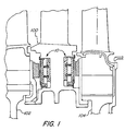
- Figure 1 is a schematic cross-sectional view of a static vane and two rotors adjacent thereto in a gas turbine and of portions of two face seals in accordance with this invention
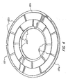
- Figure 2A is an exploded perspective view of a face seals according to one embodiment of the present invention.
- Figure 2B is a cross-sectional view of the face seals of Figure 2A, as assembled;
- Figure 3 is a schematic cross-sectional view of the top plate of the face seals of Figures 2A and 2B;
- Figure 4 illustrates an alternative embodiment of a top plate for a face seals according to this invention.
- Gas film riding seals have found wide acceptance in pipeline and process industry turbomachinery. However, such seals have not found utility in gas turbine prime movers.
- the gas turbine operating environment requires that the seals operate at relatively high surface velocities and higher temperatures than those of all other applications, and flight-worthy gas turbines must meet additional restrictions on the allowable size and weight of the seal.
- the structural portions of an aircraft engine are lightweight, which means that the seal cannot be completely isolated from the distortion of the surrounding structure. It is this last problem which more than anything else has prevented the use of film-riding bearings in gas turbine aircraft engines.
- Such a face seal comprises a top plate having a seal face that has (at least when it is bearing an axial load) a generally undulate (i.e., not flat, but stepped, sinusoidal, etc.) surface as sensed rotationally, i.e., as sensed along a circular path on the surface of the seal face.
- the top plate has a seal face (i.e., an outward facing top surface) on one side, and a top plate support surface on the other.
- the top plate is flexible and the seal assembly is designed to accommodate axial misalignments, seal face distortions, and axial excursions between the seal and the rotating part it faces.
- the invention finds use in gas turbines, including aircraft engines.
- a seal according to this invention is mounted on a stationary structure with the seal face disposed against, or adjacent to, an adjacent rotating structure.
- the structure on which the seal is mounted will be referred to herein as the stationary structure, and the structure that the seal faces will be referred to as the rotating structure or "disc”.
- the seal of this invention has demonstrated an ability to handle seal face distortion far in excess of any other gas film riding seal. It can operate over a wide range of diameters and a wide range of pressure differentials and so can be used in a variety of locations within a turbine, e.g., about 30 to 46 cm (about 12 to 18 inches).
- a preliminary engine design study produced anticipated operating conditions for the seal at three selected turbine rim locations. The first location listed in TABLE I (location 1 V-1B) is between the turbine inlet vane and the first stage turbine rotor.
- the second two locations (1B-2V, 2V-2B) seal a vane located between two turbine stages, as depicted schematically in Figure 1 wherein foil seals 10, which do not include casings, are mounted in annular grooves in a turbine stage 100 to provide a dynamic seal relative to rotating vanes 102 and 104.
- This is a very common turbine sealing application.
- the anticipated operating conditions for such a device are presented in TABLE I.
- the ⁇ P max and ⁇ P min indicate the range of the pressure differential across the seal surface.
- the "conical distortion” (or “conical out of flat”) indicates the angle formed by the top plate relative to a plane perpendicular to the axis of rotation.
- the “circular distortion” (or “circular out of flat”) indicates the amount by which an edge of the seal deviates from a plane at right angles to the axis of rotation of the rotors.
- Radial excursion refers to movement of the rotor relative to the stationary vane in the direction along the axis of rotation.
- Axial excursion refers to the movement of the axis of rotation relative to the stationary vane.
- Maximum speed refers to the maximum velocity of the outer circumference of the foil seal.
- This invention provides a face seal that can function within the foregoing parameters because the face comprises a flexible top plate or foil that will flex to accommodate out-of-flatness distortions of the seal mating disc that is supported in a manner to permit such flexure and to accommodate much larger axial excursions between the rotating and stationary portions as well.
- the top plate of a seal has an uneven seal face, at least when it is subjected to an axial load. It is the non-flat configuration of the seal face relative to the disc that allows the seal to generate the gas film between them at sufficient rotational speed.
- the non-flat surface can be inherent on the top plate in its non-loaded configuration, or the top plate can have an initially flat face when at rest, but in such case, the seal must be configured to allow the top plate to deform into a non-flat configuration when subjected to an axial load from the disc. This can be achieved, for example, by providing a top plate with a normally flat face on a support plate that provides an irregular support surface.
- the seal comprises a support spring system (i.e., one or more springs and associated support structures) beneath the top plate.
- the support spring system supports the top plate over the stationary structure and permits it to conform to the various distortions, misalignments and excursions described above.
- One such support system provides one or more springs that support the top plate, but which permit it to flex in response to the out-of-flatness distortions, and one or more springs to permit the top plate to move axially along the axis of rotation of the rotating part.
- the gas film between the top plate and the disc inhibits gas flow between the inner and outer regions of the seal, thus permitting the maintenance of a pressure differential across the seal face.
- a seal must be established between the seal structure and the stationary member on which it is mounted. This is achieved by providing a seal ring around the inner or outer circumference of the top plate, and between the seal ring and the stationary structure.
- Such an arrangement is illustrated in Figure 1, wherein labyrinth ring seals are secured around the inner edges of the top plates and bear against groove walls in the stationary structure.
- the seal assembly can be mounted in a case. In such case, a seal ring is positioned between the case and the top plate, and the case is mounted on the stationary member in a manner that prevents gas flow between the case and the stationary member.
- seal 10 having a diameter of about 12 centimeters (cm) ( 4.7 inches) comprises an annular face seal case 12, a spring base plate 14, a support plate 16, springs 18, a bump plate 20, a top plate 22 and a seal ring 24. Seal 10 also comprises two retaining rings, an inner retaining ring 26 and an outer retaining ring 28.
- Face seal case 12 defines a flat face 12a and two concentric flanges, including an inner flange 12b having an interior diameter of about 4.1 cm (1.6 inches) and a thickness of about 0.63 millimeters (mm) (0.025 inch) and an outer flange 12c.
- outer flange 12c rises to a greater height than inner flange 12b relative to face 12a by about 2.54 mm (0.1 inch).
- face 12a and flanges 12b and 12c define an annular channel within which the other structures of this particular embodiment are disposed.
- the exterior of case 12 is smooth and configured so that when mounted on a stationary structure a physical seal is easily formed between the stationary structure and the case.
- Spring base plate 14 is annular in configuration and rests directly on face 12a within flanges 12b and 12c.
- the support spring system of this embodiment comprises a plurality of springs 18 (referred to herein as "secondary springs") are mounted on spring base plate 14 to support a support plate 16 in spaced relation to spring base plate 14. Springs 18 are configured to bear the expected axial load and to accommodate the expected axial excursions set forth in Table I above.
- the support spring system also comprises the annular bump plate 20, which is mounted on support plate 16.
- Bump plate 20 carries a plurality of primary springs 20a mounted thereon. Springs 20a can be mounted on the underside of plate 20 and bear against supporting plate 16 or on the top side or plate 20 (as shown) and bear against top plate 22.
- primary springs 20a are in the form of corrugated metal sector-shaped coupons that are configured to occupy annular sectors of bump plate 20 and are each secured to plate 20b at one edge thereof.
- Springs 20a are configured to bear the expected axial load and to accommodate out-of-flatness deviations indicated in Table I.
- the corrugations flatten somewhat in response to pressure from top plate 22 and thus provide a spring-like cushioning effect.
- Annular top plate 22 is mounted on the bump plate 20 and seal ring 24 is disposed therein.
- Seal ring 24 establishes a seal between top plate 22 and case 12 and, in the illustrated embodiment, is configured to provide a labyrinth seal at inner flange 12b, but other types of seal may be used in its place, e.g., a bush seal, a metal o-ring, a segmented tilt pad seal (as shown, e.g., in the article by J. Munson, D. Grant and G.
- the seal may be formed about either the inner or the outer circumference of the to plate and the casing.
- Several keys 30 are situated within case 12, and plates 14, 16, 20 and 22 are all notched to mate with the keys 30 and thus maintain their orientation within face seal case 12 at all times.
- Outer retaining ring 28 retains plates 14, 16, 20 and 22 within face seal case 12.
- support plate 16, bump plate 20 and top plate 22 are all configured to be situated between flanges 12b and 12c (i.e., within case 12), and at an offset from the interior of flange 12b.
- Seal ring 24 is situated within the offset between inner flange 12b and top plate 22.
- Inner retaining ring 26 holds seal ring 24 in place on face seal case 12.
- Seal ring 24 defines a mounting flange 24a and is configured to overlap supporting plate 16 and thus retain plate 16 in face seal case 12.
- the seal has an annular configuration that defines an interior region 40 and an exterior region about the outer perimeter of the seal.
- top plate 22 has a flat bottom support surface 22d that contacts bump plate 20.
- the top surface (or “face") of top plate 22 is stepped so that the height of the face of top plate 22 relative to the bottom support surface 22d is generally uniform along any given radius, but it changes in a rotational direction, e.g., as sensed in the rotational direction of arrow 22c (Fig. 2A).
- the top surface of top plate 22 has a sawtooth-like rotational surface profile in which the overall thickness of the top plate repeatedly decreases quickly and then increases gradually in the direction of arrow 22c.
- a series of thin, flat, circularly arranged overlapping, sector-shaped pads or scales 22b Fig.
- top plate 22 has a generally undulate face surface even when it is not bearing an axial load.
- the top plate may have a flat face when not bearing a load, and there may be structures beneath the top plate which, when the top plate bears an axial load, deforms the top plate so that the top surface is no longer flat, thus enabling it to form a gas seal between it and an adjacent rotating surface.
- the top surface of top plate 22, i.e., the top surfaces of scales 22b, is coated to provide a high-temperature, low-friction surface, to permit contact with a rotating structure with a minimum of wear on the structure and on scales 22b.
- the surface can be coated with a polyimid, or a ceramic high-temperature material.
- the disc can be coated if the top plate is not; optionally, both facing surfaces are coated. The coating prevents wear on the parts while they are in contact before the gas film is formed.
- bearing 10 may be secured to a section of a gas turbine that faces another and rotates relative to it, e.g., by securing case 12 to a turbine inlet vane with the stepped face of top plate 22 facing the rotor.
- seal 10 When seal 10 is concentric with the axis of rotation and other conditions described herein, such as speed of rotation and axial load, are met, a gap will develop between the face seal device and the rotating part (i.e., the rotor), where a thin film of air will be maintained between them. The thin film of air will protect the mating surfaces from wear and will also establish a barrier to the transfer of gases through the gap.
- the primary springs 20a enable the device to accommodate primary deviations in the seal, e.g., misalignments, out-of-flatness, conical distortion and circumferential distortion, while the secondary springs 18 enable the device to tolerate substantial axial movement.
- the axial movements accommodated by the primary springs and the secondary springs may be expected to differ by up to two orders of magnitude and the springs are chosen accordingly.
- a prototype face seal bearing like the one shown in Figures 2A and 2B was tested in a test rig.
- the test seal had a diameter of about 12.7 cm (5 inches), and included a top plate that had eight pads, each having a thickness of 0.524 mm (0.006 inch).
- the inner diameter of the top plate measured about 5.97 cm (2.35 inches) and the outer diameter measured about 10.77 cm (4.24 inches) and had a circumference of about 33 cm (13 inches).
- the face seal was mounted on a non-rotating piston that provided axial load at typical operating levels, and air bearings located the piston shaft radially.
- a rotatable thrust runner was positioned against the face and was rotated at 60,000 rpm, giving a circumferential velocity of about 335.3 meters/second (1100 feet per second).
- Various levels of thrust load were applied against the face of the bearing and the bearing was spun up to surface speeds equivalent to those shown in TABLE I and then allowed to coast down. Torque was measured continuously during these tests. The speed at which lift-off occurs, i.e., at which the film of air develops between top plate 22 and the thrust runner, was documented by noting the precipitous change in torque that accompanied lift-off.
- a family of curves was generated by repeating the same experiment with increased thrust load. These data allow comparisons of film stiffness and load capacity to be made between seals of different design. High film stiffness and load capacity are preferred.
- the prototypes that have been tested will all support a nominal 10 psi bearing load.
- a face seal according to Figures 2A and 2B was tested repeatedly for conical distortion of the top plate of 0.52° and 0.32°.
- two simulator plates were manufactured to simulate the expected conical distortion between the thrust runner and the face seal.
- the distortion was created in the top plate by installing the top plate and the bump plate on the simulator plate, which was used instead of the flat support plate 16 in Fig. 2A.
- the face seal results were compared with flat face seal results for performance and load capacity. Testing was done as described above using the standard flat backing plate before the conical tests and then after the testing was completed. There was no significant difference in torque results.
- simulator plates were manufactured with circumferential undulation, i.e., deviation from flatness, and were incorporated into face seals as shown in Figures 2A and 2B. Testing was conducted as described above with plates that had one wavelength per circumference and an "out-of-flatness" or wave amplitude of 0.2286 mm (0.009 inch) and 0.1016 mm (0.004 inch), and one, one-and-one-half, and two waves per circumference. In all cases, the top plate and bump plate were installed on top of the undulate simulator, which caused the top plate to take on the shape of the simulator plate.
- the data of Table III show that by making at least a portion of the seal, e.g., the top plate and the bump plate, the seal can be made to track very large distortions of the rotating mating ring relative to prior art film riding face seal technology, e.g., distortion levels that are more than two orders of magnitude greater than what conventional face seal bearing can tolerate.
- the torque readings for the circumferentially undulate tests are lower in both cases than for the standard flat plates. This can be explained if the assumption is made that more of the axial load is being carried by the peak areas of the undulation.
- the average film thickness therefore is increased and, since torque is inversely proportional to the third power of film thickness, one would expect a decrease in torque with an increase in average film thickness.
- FIG. 4 illustrates a top plate 122 having two concentric arrangements of pads, an outer ring of pads 122b, and an inner ring of pads 122b', on a top base 122a.
- Figure 4 also illustrates a top plate 122 that comprises pads that do not overlap, but which nonetheless yield a generally undulate seal face because the pads are situated to leave grooves 122c between them.
- the seal is relatively lightweight since most of it is constructed of sheet metal; it is relatively inexpensive since it is constructed primarily of readily available sheet metal and it is not necessary to manufacture fine groove features to generate lift since the pads distort to create lift on their own; it should be relatively robust since there are no fine features to clog in service; and there are no limitations on increasing the size of the seal to diameters required for the turbine rim locations.
- the ability of the pads to rise from the top base allows the seal to respond locally to local distortions in the air film due to changes in operating conditions, foreign objects in the film, etc.
- Advantages of this invention include the ability of the seal to track circumferential out of roundness; the ability to easily scale the design by simply adding or subtracting segments; the lack of need for fine geometry to generate lift using the tilt pad concept; and superior robustness of the seal since there would be no fine geometry features that could wear or become clogged in service.
Landscapes
- Engineering & Computer Science (AREA)
- General Engineering & Computer Science (AREA)
- Mechanical Engineering (AREA)
- Physics & Mathematics (AREA)
- Geometry (AREA)
- Fluid Mechanics (AREA)
- Turbine Rotor Nozzle Sealing (AREA)
- Support Of The Bearing (AREA)
- Sealing Devices (AREA)
- Sealing Using Fluids, Sealing Without Contact, And Removal Of Oil (AREA)
- Mechanical Sealing (AREA)
- Gasket Seals (AREA)
- Laminated Bodies (AREA)
Claims (16)
- Joint annulaire plat à gaz (10) destiné à être monté entre une première structure et une seconde structure adjacente, au moins une des structures étant orientable par rapport à l'autre, dans lequel :le joint plat comprend une plaque supérieure annulaire (22) destinée à être montée sur une telle première structure, la plaque supérieure présentant une surface de face ondulée, au moins lorsque de telles structures sont en rotation l'une par rapport à l'autre, pour générer un film de gaz entre la plaque supérieure (22) et une telle seconde structure ; caractérisé en ce que la plaque supérieure présente sur sa surface de face une pluralité de plaques sectorielles (22b) et est déformable pour fléchir afin de s'adapter aux déformations avec courbure d'un disque d'accouplement de joint sur la seconde structure, et le joint à faces planes comprend en outre :une bague d'étanchéité (24) positionnée pour empêcher l'écoulement gazeux entre le joint plat 10) et ladite première structure, etun système de ressort de support (14, 18, 20, 20a) pour adapter la plaque supérieure aux déformations à courbure et aux courses axiales entre les structures en rotation tout en maintenant le film de gaz pour maintenir un joint à gaz à travers la plaque supérieure annulaire (22).
- Joint plat selon la revendication 1, dans lequel la bague d'étanchéité (24) est fixée à la plaque supérieure.
- Joint plat selon la revendication 1 ou la revendication 2, dans lequel la bague d'étanchéité (24) comprend un joint à labyrinthe.
- Joint plat selon au moins une des revendications précédentes, dans lequel les moyens de support comprennent un système de ressort principal (20, 20a) pour résister aux déformations avec courbure, et un système de ressort secondaire (14, 18) pour s'adapter aux courses axiales.
- Joint plat selon la revendication 4, dans lequel le système de ressort de support comprend une plaque de support (16) présentant deux côtés, dans lequel le système de ressort principal (20, 20a) est d'un côté de la plaque de support, et le système de ressort secondaire (14, 18) est de l'autre côté de la plaque de support par rapport au système de ressort principal.
- Joint plat selon l'une quelconque des revendications 1, 2, 3 ou 4, dans lequel la pluralité de plaques sectorielles sur la surface de face se chevauchent les unes les autres pour former une surface ondulée même lorsqu'aucune de ces première et seconde structures n'est en rotation.
- Joint plat selon au moins une des revendications précédentes, comprenant une plaque supérieure (22) qui est plane lorsqu'elle est au repos, dans lequel le joint plat est configuré pour permettre la déformation de la plaque supérieure dans une configuration non plane lorsque les structures sont en rotation l'une par rapport à l'autre.
- Joint plat selon au moins une des revendications 1 à 5 et 7, dans lequel la pluralité de plaques sectorielles (22b) sur la surface de face sont disposées à distance les unes des autres pour définir des rainures entre elles pour former une surface ondulée même lorsqu'aucune de ces première et seconde structures n'est en rotation.
- Joint à faces plat selon au moins une des revendications 4 et 5, comprenant en outre un boîtier (12) qui est dimensionné et configuré pour être fixé de manière étanche à une telle première structure, et à l'intérieur duquel la plaque supérieure (22), le système de ressort principal (20, 20a) et le système de ressort secondaire (14, 18) sont fixés, et dans lequel la bague (24) établit un joint entre la plaque supérieure (22) et le boîtier (12).
- Joint à faces planes selon au moins une des revendications précédentes, dans lequel la plaque supérieure (22) comprend une surface à faible usure et à frottement réduit.
- Joint plat selon au moins une des revendications précédentes, dans lequel le joint plat (10) est monté sur la première structure adjacente à la seconde structure, et la première structure est fixe et la seconde structure est tournante.
- Joint plat selon au moins une des revendications 1 à 10, dans lequel le joint plat (10) est monté sur la première structure adjacente à la seconde structure, et la seconde structure est tournante.
- Joint plat selon la revendication 6, dans lequel les plaques sectorielles (22b) sont fixées de manière articulée à la plaque supérieure (22).
- Procédé pour maintenir une pression différentielle à travers un joint plat à gaz (10) séparant une première région contenant du gaz à une première pression d'une seconde région contenant du gaz à une seconde pression qui est différente de la première pression ; le joint plat comprenant (a) une plaque supérieure annulaire (22) montée sur une première structure adjacente à une seconde structure, au moins une des structures étant tournante par rapport à l'autre, la plaque supérieure présentant une surface de face ondulée, au moins lorsque les structures sont en rotation l'une par rapport à l'autre, pour générer un film de gaz entre la plaque supérieure (22) et la seconde structure ; caractérisé en ce que la plaque supérieure présente sur sa surface de face une pluralité de plaques sectorielles (22b) et est déformable pour fléchir afin de résister à des déformations à courbure d'un disque d'accouplement de joint sur la seconde structure, et le joint plat comprend en outre: (b) une bague d'étanchéité (24) positionnée pour empêcher l'écoulement gazeux entre le joint à faces planes (10) et ladite première structure, et (c) un système de ressort de support pour adapter la plaque supérieure aux déformations à courbure et aux courses axiales entre les structures en rotation tout en maintenant le film de gaz en tant que joint à gaz à travers la plaque supérieure annulaire et entre les première et seconde régions, le procédé comprenant l'étape consistant à mettre en rotation au moins une des première et seconde structures l'une par rapport à l'autre à une vitesse au moins suffisante pour établir et maintenir le joint à gaz.
- Procédé selon la revendication 14, comprenant l'étape consistant à maintenir la première structure fixe et à mettre en rotation la seconde structure.
- Joint à faces planes selon la revendication 5, dans lequel le système de ressort principal (20, 20a) est disposé entre la plaque supérieure (22) et la plaque de support (16).
Applications Claiming Priority (3)
| Application Number | Priority Date | Filing Date | Title |
|---|---|---|---|
| US30358801P | 2001-07-06 | 2001-07-06 | |
| US303588P | 2001-07-06 | ||
| PCT/US2002/021191 WO2003004911A2 (fr) | 2001-07-06 | 2002-07-03 | Joint hydrodynamique a faces planes pose sur un film metallique |
Publications (3)
| Publication Number | Publication Date |
|---|---|
| EP1412663A2 EP1412663A2 (fr) | 2004-04-28 |
| EP1412663A4 EP1412663A4 (fr) | 2004-09-08 |
| EP1412663B1 true EP1412663B1 (fr) | 2007-02-07 |
Family
ID=23172777
Family Applications (1)
| Application Number | Title | Priority Date | Filing Date |
|---|---|---|---|
| EP02756377A Expired - Lifetime EP1412663B1 (fr) | 2001-07-06 | 2002-07-03 | Joint hydrodynamique a faces planes pose sur un film metallique |
Country Status (6)
| Country | Link |
|---|---|
| US (1) | US7261300B2 (fr) |
| EP (1) | EP1412663B1 (fr) |
| AT (1) | ATE353416T1 (fr) |
| AU (1) | AU2002322389A1 (fr) |
| DE (1) | DE60218045T2 (fr) |
| WO (1) | WO2003004911A2 (fr) |
Cited By (1)
| Publication number | Priority date | Publication date | Assignee | Title |
|---|---|---|---|---|
| US9109459B2 (en) | 2013-11-11 | 2015-08-18 | General Electric Company | Apparatus and systems for sealing a rotary machine using a self-cleaning face seal |
Families Citing this family (51)
| Publication number | Priority date | Publication date | Assignee | Title |
|---|---|---|---|---|
| US7287756B2 (en) * | 2004-03-08 | 2007-10-30 | Westinghouse Electric Co Llc | Film riding shaft seal |
| US7216871B1 (en) * | 2004-05-04 | 2007-05-15 | Advanced Components & Materials, Inc. | Non-contacting seal for rotating surfaces |
| US7535150B1 (en) | 2006-05-08 | 2009-05-19 | Prc Laser Corporation | Centrifugal turbine blower with gas foil bearings |
| US7883311B2 (en) * | 2006-12-20 | 2011-02-08 | General Electric Company | Bearing assembly and method of assembling the same |
| US7948105B2 (en) * | 2007-02-01 | 2011-05-24 | R&D Dynamics Corporation | Turboalternator with hydrodynamic bearings |
| US20080232962A1 (en) * | 2007-03-20 | 2008-09-25 | Agrawal Giridhari L | Turbomachine and method for assembly thereof using a split housing design |
| KR101204867B1 (ko) * | 2007-04-02 | 2012-11-26 | 삼성테크윈 주식회사 | 에어 포일 베어링 |
| US20080309019A1 (en) * | 2007-06-13 | 2008-12-18 | General Electric Company | Sealing assembly for rotary machines |
| US8105021B2 (en) * | 2007-08-20 | 2012-01-31 | United Technologies Corp. | Gas turbine engine systems involving hydrostatic face seals with integrated back-up seals |
| US8109716B2 (en) * | 2007-08-17 | 2012-02-07 | United Technologies Corp. | Gas turbine engine systems involving hydrostatic face seals with anti-fouling provisioning |
| US8109717B2 (en) * | 2007-08-17 | 2012-02-07 | United Technologies Corp. | Gas turbine engine systems involving hydrostatic face seals with integrated back-up seals |
| US20090051120A1 (en) * | 2007-08-23 | 2009-02-26 | United Technologies Corp. | Gas Turbine Engine Systems Involving Hydrostatic Face Seals |
| US7797941B2 (en) * | 2007-10-26 | 2010-09-21 | United Technologies Corporation | Gas turbine engine systems involving hydrostatic face seals |
| GB0724122D0 (en) * | 2007-12-11 | 2008-01-23 | Rubberatkins Ltd | Sealing apparatus |
| US8167545B2 (en) * | 2008-02-27 | 2012-05-01 | United Technologies Corp. | Self-balancing face seals and gas turbine engine systems involving such seals |
| EP2329157A4 (fr) * | 2008-08-25 | 2014-01-22 | Kturbo Inc | Palier-feuille de butée |
| EP2189630A1 (fr) * | 2008-11-19 | 2010-05-26 | Siemens Aktiengesellschaft | Turbine à gaz, support d'aube directrice pour une telle turbine à gaz, et moteur à turbine à gaz avec une telle turbine à gaz |
| US9951784B2 (en) | 2010-07-27 | 2018-04-24 | R&D Dynamics Corporation | Mechanically-coupled turbomachinery configurations and cooling methods for hermetically-sealed high-temperature operation |
| US10006465B2 (en) | 2010-10-01 | 2018-06-26 | R&D Dynamics Corporation | Oil-free water vapor blower |
| US8439567B1 (en) * | 2010-11-10 | 2013-05-14 | Curtiss-Wright Electro-Mechanical Corporation | Disc springs/carrier plate preload assembly |
| US9145785B2 (en) | 2011-03-04 | 2015-09-29 | General Electric Company | Aerodynamic seal assemblies for turbo-machinery |
| US20120248704A1 (en) * | 2011-03-29 | 2012-10-04 | Alstom Technology Ltd. | Film riding seal for turbines |
| US9476428B2 (en) | 2011-06-01 | 2016-10-25 | R & D Dynamics Corporation | Ultra high pressure turbomachine for waste heat recovery |
| US20130075976A1 (en) * | 2011-09-22 | 2013-03-28 | Todd A. Davis | Compliant mounting of an axial face seal assembly |
| US9062712B1 (en) | 2012-02-27 | 2015-06-23 | The United States Of America As Represented By The Administrator Of The National Aeronautics And Space Administration | Passive thermal management of foil bearings |
| US9255642B2 (en) | 2012-07-06 | 2016-02-09 | General Electric Company | Aerodynamic seals for rotary machine |
| US9587746B2 (en) | 2012-07-31 | 2017-03-07 | General Electric Company | Film riding seals for rotary machines |
| US9115810B2 (en) * | 2012-10-31 | 2015-08-25 | General Electric Company | Pressure actuated film riding seals for turbo machinery |
| US9045994B2 (en) * | 2012-10-31 | 2015-06-02 | General Electric Company | Film riding aerodynamic seals for rotary machines |
| US9291067B2 (en) | 2013-11-11 | 2016-03-22 | General Electric Company | Rotary machine aspirating seal assembly and method of assembling the same |
| US10041367B2 (en) | 2013-12-12 | 2018-08-07 | General Electric Company | Axially faced seal system |
| US20150285152A1 (en) * | 2014-04-03 | 2015-10-08 | United Technologies Corporation | Gas turbine engine and seal assembly therefore |
| US9957826B2 (en) | 2014-06-09 | 2018-05-01 | United Technologies Corporation | Stiffness controlled abradeable seal system with max phase materials and methods of making same |
| US10161259B2 (en) * | 2014-10-28 | 2018-12-25 | General Electric Company | Flexible film-riding seal |
| US10145377B2 (en) | 2015-04-02 | 2018-12-04 | Curtiss-Wright Electro-Mechanical Corporation | Canned motor pump thrust shoe heat shield |
| CN104913064B (zh) * | 2015-05-29 | 2017-03-08 | 浙江工业大学 | 一种悬臂型箔片端面气膜密封结构 |
| CN104913061B (zh) * | 2015-06-15 | 2017-03-08 | 浙江工业大学 | 一种可双向旋转的箔片端面气膜密封结构 |
| US9976420B2 (en) | 2015-07-23 | 2018-05-22 | General Electric Company | Aspirating seal assembly and method of assembling |
| KR101868576B1 (ko) * | 2015-10-26 | 2018-06-19 | 말레동현필터시스템 주식회사 | 엔진의 가스켓 조립체 |
| US10422240B2 (en) * | 2016-03-16 | 2019-09-24 | United Technologies Corporation | Turbine engine blade outer air seal with load-transmitting cover plate |
| KR101846668B1 (ko) * | 2016-05-09 | 2018-04-09 | 현대자동차주식회사 | 쓰러스트 베어링 |
| CN106090223B (zh) * | 2016-07-15 | 2017-11-07 | 浙江工业大学 | 一种高压形变跨尺度型孔织构的箔片端面气膜密封结构 |
| KR102552483B1 (ko) * | 2016-12-05 | 2023-07-06 | 현대자동차주식회사 | 에어 포일 스러스트 베어링 |
| CN107289136A (zh) * | 2017-07-06 | 2017-10-24 | 南阳神鹰装备制造有限公司 | 一种用于旋转机械的空气悬浮型密封结构 |
| CN111041801B (zh) * | 2018-10-15 | 2021-08-10 | 广东美的白色家电技术创新中心有限公司 | 滤网组件、底座总成、干衣机及洗烘一体机 |
| WO2020130124A1 (fr) * | 2018-12-20 | 2020-06-25 | 株式会社Ihi | Palier de butée à plaquettes |
| CN113107966B (zh) * | 2020-01-09 | 2025-05-06 | 珠海格力电器股份有限公司 | 动压气体止推轴承及组件 |
| CN114165516A (zh) * | 2020-09-10 | 2022-03-11 | 王庆五 | 一种弹簧型箔片气体动压轴承 |
| JP7731746B2 (ja) * | 2021-09-24 | 2025-09-01 | Ntn株式会社 | フォイル軸受 |
| CN115127810B (zh) * | 2022-06-16 | 2025-09-05 | 江苏大学镇江流体工程装备技术研究院 | 非接触式平面气浮轴承试验台加载机构 |
| CN117450167B (zh) * | 2023-12-20 | 2024-03-12 | 山东华东风机有限公司 | 一种轴向箔片空气止推轴承及空压机 |
Family Cites Families (25)
| Publication number | Priority date | Publication date | Assignee | Title |
|---|---|---|---|---|
| US3382014A (en) * | 1966-02-18 | 1968-05-07 | Garrett Corp | Self-acting foil bearings |
| US3635534A (en) * | 1969-08-06 | 1972-01-18 | Garrett Corp | Self-pressurizing bearings with resilient elements |
| US4227752A (en) | 1978-12-29 | 1980-10-14 | Mechanical Technology Incorporated | Staged bearing surface compliance for hydrodynamic fluid bearing |
| US4654939A (en) * | 1979-04-27 | 1987-04-07 | The Garrett Corporation | Foil bearing surfaces and method of making same |
| US4296976A (en) * | 1980-04-03 | 1981-10-27 | Mechanical Technology Incorporated | Cross-plies support element for compliant bearings |
| US4462700A (en) | 1981-11-23 | 1984-07-31 | United Technologies Corporation | Hydrodynamic fluid film thrust bearing |
| US4621930A (en) * | 1984-10-01 | 1986-11-11 | The Garrett Corporation | Foil thrust bearing cooling |
| US4682900A (en) * | 1985-12-19 | 1987-07-28 | The Garrett Corporation | Thrust bearing underspring |
| US5246295A (en) * | 1991-10-30 | 1993-09-21 | Ide Russell D | Non-contacting mechanical face seal of the gap-type |
| US5318366A (en) * | 1992-08-24 | 1994-06-07 | Alliedsignal Inc. | Foil thrust bearing with varying radial and circumferential stiffness |
| US5474306A (en) | 1992-11-19 | 1995-12-12 | General Electric Co. | Woven seal and hybrid cloth-brush seals for turbine applications |
| AU2430195A (en) | 1994-04-20 | 1995-11-16 | Durametallic Corporation | Face seal with angled grooves |
| US5769604A (en) * | 1995-05-04 | 1998-06-23 | Eg&G Sealol, Inc. | Face seal device having high angular compliance |
| US5634723A (en) | 1995-06-15 | 1997-06-03 | R & D Dynamics Corporation | Hydrodynamic fluid film bearing |
| US6007068A (en) | 1996-11-25 | 1999-12-28 | Us Government As Represented By The Administrator Of Nasa Headquarters | Dynamic face seal arrangement |
| US5833369A (en) * | 1997-03-28 | 1998-11-10 | Mohawk Innovative Technology, Inc. | High load capacity compliant foil hydrodynamic thrust bearing |
| RU2137954C1 (ru) * | 1997-04-03 | 1999-09-20 | Московский государственный авиационный институт (технический университет) | Лепестковый газодинамический подшипник |
| US5911511A (en) * | 1997-09-26 | 1999-06-15 | Alliedsignal Inc. | Tilting pad foil thrust and journal bearings |
| US6045134A (en) | 1998-02-04 | 2000-04-04 | General Electric Co. | Combined labyrinth and brush seals for rotary machines |
| US5938341A (en) * | 1998-02-09 | 1999-08-17 | Alliedsignal Inc. | Foil thrust bearing including a follower spring having rotated, elongated spring tabs |
| US6220814B1 (en) | 1998-07-16 | 2001-04-24 | Siemens Westinghouse Power Corporation | Turbine interstage sealing arrangement |
| US6196790B1 (en) | 1998-12-17 | 2001-03-06 | United Technologies Corporation | Seal assembly for an intershaft seal in a gas turbine engine |
| KR100288315B1 (ko) | 1999-03-15 | 2001-04-16 | 김평길 | 2단 원심압축기 |
| GB0317055D0 (en) * | 2003-07-22 | 2003-08-27 | Cross Mfg Co 1938 Ltd | Improvements relating to aspirating face seals and thrust bearings |
| US20060062499A1 (en) * | 2004-04-08 | 2006-03-23 | Boyd Gary L | Integrated hydrodynamic air bearing and seal |
-
2002
- 2002-07-03 EP EP02756377A patent/EP1412663B1/fr not_active Expired - Lifetime
- 2002-07-03 WO PCT/US2002/021191 patent/WO2003004911A2/fr not_active Ceased
- 2002-07-03 AT AT02756377T patent/ATE353416T1/de not_active IP Right Cessation
- 2002-07-03 US US10/486,647 patent/US7261300B2/en not_active Expired - Fee Related
- 2002-07-03 AU AU2002322389A patent/AU2002322389A1/en not_active Abandoned
- 2002-07-03 DE DE60218045T patent/DE60218045T2/de not_active Expired - Lifetime
Cited By (1)
| Publication number | Priority date | Publication date | Assignee | Title |
|---|---|---|---|---|
| US9109459B2 (en) | 2013-11-11 | 2015-08-18 | General Electric Company | Apparatus and systems for sealing a rotary machine using a self-cleaning face seal |
Also Published As
| Publication number | Publication date |
|---|---|
| DE60218045D1 (de) | 2007-03-22 |
| WO2003004911A2 (fr) | 2003-01-16 |
| US7261300B2 (en) | 2007-08-28 |
| DE60218045T2 (de) | 2007-06-06 |
| AU2002322389A1 (en) | 2003-01-21 |
| EP1412663A2 (fr) | 2004-04-28 |
| EP1412663A4 (fr) | 2004-09-08 |
| WO2003004911B1 (fr) | 2004-04-15 |
| US20040207158A1 (en) | 2004-10-21 |
| ATE353416T1 (de) | 2007-02-15 |
| WO2003004911A3 (fr) | 2004-02-12 |
Similar Documents
| Publication | Publication Date | Title |
|---|---|---|
| EP1412663B1 (fr) | Joint hydrodynamique a faces planes pose sur un film metallique | |
| US11047481B2 (en) | Seal assembly for a rotary machine | |
| JP3555683B2 (ja) | 回転機用シールアセンブリ | |
| JP6047236B2 (ja) | 回転機械のためのフィルムライディングシール | |
| US10161259B2 (en) | Flexible film-riding seal | |
| EP0867599B1 (fr) | Méthode et dispositif d'étanchéité pour une assemblée des aubes statoriques | |
| US20190072186A1 (en) | Seal assembly for a rotary machine | |
| US4527912A (en) | Squeeze film damper | |
| US9695940B2 (en) | Bidirectional lift-off circumferential shaft seal segment and a shaft seal including a plurality of the segments | |
| US5791868A (en) | Thrust load compensating system for a compliant foil hydrodynamic fluid film thrust bearing | |
| JP3702212B2 (ja) | 軸シール機構及びタービン | |
| US4116503A (en) | Resilient foil thrust bearings | |
| EP2682567A1 (fr) | Joints aérodynamiques pour machine rotative | |
| JP3616016B2 (ja) | 軸シール機構及びガスタービン | |
| CA2483391A1 (fr) | Fixation d'une chemise de protection en ceramique dans un boitier metallique | |
| JP2006510855A (ja) | 耐荷重が増大した軸方向スラスト軸受用のコンプライアントサポート | |
| US20070248452A1 (en) | Retractable compliant abradable sealing system and method for rotary machines | |
| GB1558941A (en) | Air bearing for turbo machines | |
| US5759011A (en) | Journal bearing assembly | |
| Munson et al. | Foil face seal development | |
| CN110345160A (zh) | 机器推力轴承组件 | |
| CN210195825U (zh) | 一种端柱面结合的双作用柔性支承干气密封装置 | |
| US20060062499A1 (en) | Integrated hydrodynamic air bearing and seal | |
| Messenger et al. | Demonstration of a dynamic clearance seal in a rotating steam test facility | |
| GB2297363A (en) | Ring seal |
Legal Events
| Date | Code | Title | Description |
|---|---|---|---|
| PUAI | Public reference made under article 153(3) epc to a published international application that has entered the european phase |
Free format text: ORIGINAL CODE: 0009012 |
|
| 17P | Request for examination filed |
Effective date: 20040127 |
|
| AK | Designated contracting states |
Kind code of ref document: A2 Designated state(s): AT BE BG CH CY CZ DE DK EE ES FI FR GB GR IE IT LI LU MC NL PT SE SK TR |
|
| AX | Request for extension of the european patent |
Extension state: AL LT LV MK RO SI |
|
| A4 | Supplementary search report drawn up and despatched |
Effective date: 20040727 |
|
| RIC1 | Information provided on ipc code assigned before grant |
Ipc: 7F 16C 17/12 B Ipc: 7F 16J 15/34 A |
|
| 17Q | First examination report despatched |
Effective date: 20050131 |
|
| GRAP | Despatch of communication of intention to grant a patent |
Free format text: ORIGINAL CODE: EPIDOSNIGR1 |
|
| GRAS | Grant fee paid |
Free format text: ORIGINAL CODE: EPIDOSNIGR3 |
|
| GRAA | (expected) grant |
Free format text: ORIGINAL CODE: 0009210 |
|
| AK | Designated contracting states |
Kind code of ref document: B1 Designated state(s): AT BE BG CH CY CZ DE DK EE ES FI FR GB GR IE IT LI LU MC NL PT SE SK TR |
|
| PG25 | Lapsed in a contracting state [announced via postgrant information from national office to epo] |
Ref country code: FI Free format text: LAPSE BECAUSE OF FAILURE TO SUBMIT A TRANSLATION OF THE DESCRIPTION OR TO PAY THE FEE WITHIN THE PRESCRIBED TIME-LIMIT Effective date: 20070207 Ref country code: BE Free format text: LAPSE BECAUSE OF FAILURE TO SUBMIT A TRANSLATION OF THE DESCRIPTION OR TO PAY THE FEE WITHIN THE PRESCRIBED TIME-LIMIT Effective date: 20070207 Ref country code: DK Free format text: LAPSE BECAUSE OF FAILURE TO SUBMIT A TRANSLATION OF THE DESCRIPTION OR TO PAY THE FEE WITHIN THE PRESCRIBED TIME-LIMIT Effective date: 20070207 Ref country code: AT Free format text: LAPSE BECAUSE OF FAILURE TO SUBMIT A TRANSLATION OF THE DESCRIPTION OR TO PAY THE FEE WITHIN THE PRESCRIBED TIME-LIMIT Effective date: 20070207 Ref country code: CH Free format text: LAPSE BECAUSE OF FAILURE TO SUBMIT A TRANSLATION OF THE DESCRIPTION OR TO PAY THE FEE WITHIN THE PRESCRIBED TIME-LIMIT Effective date: 20070207 Ref country code: LI Free format text: LAPSE BECAUSE OF FAILURE TO SUBMIT A TRANSLATION OF THE DESCRIPTION OR TO PAY THE FEE WITHIN THE PRESCRIBED TIME-LIMIT Effective date: 20070207 Ref country code: NL Free format text: LAPSE BECAUSE OF FAILURE TO SUBMIT A TRANSLATION OF THE DESCRIPTION OR TO PAY THE FEE WITHIN THE PRESCRIBED TIME-LIMIT Effective date: 20070207 |
|
| REG | Reference to a national code |
Ref country code: GB Ref legal event code: FG4D |
|
| REG | Reference to a national code |
Ref country code: CH Ref legal event code: EP |
|
| REG | Reference to a national code |
Ref country code: IE Ref legal event code: FG4D |
|
| REF | Corresponds to: |
Ref document number: 60218045 Country of ref document: DE Date of ref document: 20070322 Kind code of ref document: P |
|
| PG25 | Lapsed in a contracting state [announced via postgrant information from national office to epo] |
Ref country code: SE Free format text: LAPSE BECAUSE OF FAILURE TO SUBMIT A TRANSLATION OF THE DESCRIPTION OR TO PAY THE FEE WITHIN THE PRESCRIBED TIME-LIMIT Effective date: 20070507 |
|
| PG25 | Lapsed in a contracting state [announced via postgrant information from national office to epo] |
Ref country code: BG Free format text: LAPSE BECAUSE OF THE APPLICANT RENOUNCES Effective date: 20070508 |
|
| PG25 | Lapsed in a contracting state [announced via postgrant information from national office to epo] |
Ref country code: ES Free format text: LAPSE BECAUSE OF FAILURE TO SUBMIT A TRANSLATION OF THE DESCRIPTION OR TO PAY THE FEE WITHIN THE PRESCRIBED TIME-LIMIT Effective date: 20070518 |
|
| PG25 | Lapsed in a contracting state [announced via postgrant information from national office to epo] |
Ref country code: PT Free format text: LAPSE BECAUSE OF FAILURE TO SUBMIT A TRANSLATION OF THE DESCRIPTION OR TO PAY THE FEE WITHIN THE PRESCRIBED TIME-LIMIT Effective date: 20070709 |
|
| NLV1 | Nl: lapsed or annulled due to failure to fulfill the requirements of art. 29p and 29m of the patents act | ||
| REG | Reference to a national code |
Ref country code: CH Ref legal event code: PL |
|
| EN | Fr: translation not filed | ||
| PG25 | Lapsed in a contracting state [announced via postgrant information from national office to epo] |
Ref country code: SK Free format text: LAPSE BECAUSE OF FAILURE TO SUBMIT A TRANSLATION OF THE DESCRIPTION OR TO PAY THE FEE WITHIN THE PRESCRIBED TIME-LIMIT Effective date: 20070207 |
|
| PLBE | No opposition filed within time limit |
Free format text: ORIGINAL CODE: 0009261 |
|
| STAA | Information on the status of an ep patent application or granted ep patent |
Free format text: STATUS: NO OPPOSITION FILED WITHIN TIME LIMIT |
|
| PG25 | Lapsed in a contracting state [announced via postgrant information from national office to epo] |
Ref country code: CZ Free format text: LAPSE BECAUSE OF FAILURE TO SUBMIT A TRANSLATION OF THE DESCRIPTION OR TO PAY THE FEE WITHIN THE PRESCRIBED TIME-LIMIT Effective date: 20070207 |
|
| 26N | No opposition filed |
Effective date: 20071108 |
|
| PG25 | Lapsed in a contracting state [announced via postgrant information from national office to epo] |
Ref country code: GR Free format text: LAPSE BECAUSE OF FAILURE TO SUBMIT A TRANSLATION OF THE DESCRIPTION OR TO PAY THE FEE WITHIN THE PRESCRIBED TIME-LIMIT Effective date: 20070508 Ref country code: IT Free format text: LAPSE BECAUSE OF FAILURE TO SUBMIT A TRANSLATION OF THE DESCRIPTION OR TO PAY THE FEE WITHIN THE PRESCRIBED TIME-LIMIT Effective date: 20070207 Ref country code: FR Free format text: LAPSE BECAUSE OF FAILURE TO SUBMIT A TRANSLATION OF THE DESCRIPTION OR TO PAY THE FEE WITHIN THE PRESCRIBED TIME-LIMIT Effective date: 20070928 Ref country code: MC Free format text: LAPSE BECAUSE OF NON-PAYMENT OF DUE FEES Effective date: 20070731 |
|
| PG25 | Lapsed in a contracting state [announced via postgrant information from national office to epo] |
Ref country code: IE Free format text: LAPSE BECAUSE OF NON-PAYMENT OF DUE FEES Effective date: 20070703 |
|
| PG25 | Lapsed in a contracting state [announced via postgrant information from national office to epo] |
Ref country code: FR Free format text: LAPSE BECAUSE OF FAILURE TO SUBMIT A TRANSLATION OF THE DESCRIPTION OR TO PAY THE FEE WITHIN THE PRESCRIBED TIME-LIMIT Effective date: 20070207 |
|
| PG25 | Lapsed in a contracting state [announced via postgrant information from national office to epo] |
Ref country code: EE Free format text: LAPSE BECAUSE OF FAILURE TO SUBMIT A TRANSLATION OF THE DESCRIPTION OR TO PAY THE FEE WITHIN THE PRESCRIBED TIME-LIMIT Effective date: 20070207 |
|
| PG25 | Lapsed in a contracting state [announced via postgrant information from national office to epo] |
Ref country code: CY Free format text: LAPSE BECAUSE OF FAILURE TO SUBMIT A TRANSLATION OF THE DESCRIPTION OR TO PAY THE FEE WITHIN THE PRESCRIBED TIME-LIMIT Effective date: 20070207 |
|
| PG25 | Lapsed in a contracting state [announced via postgrant information from national office to epo] |
Ref country code: LU Free format text: LAPSE BECAUSE OF NON-PAYMENT OF DUE FEES Effective date: 20070703 |
|
| PG25 | Lapsed in a contracting state [announced via postgrant information from national office to epo] |
Ref country code: TR Free format text: LAPSE BECAUSE OF FAILURE TO SUBMIT A TRANSLATION OF THE DESCRIPTION OR TO PAY THE FEE WITHIN THE PRESCRIBED TIME-LIMIT Effective date: 20070207 |
|
| PGFP | Annual fee paid to national office [announced via postgrant information from national office to epo] |
Ref country code: DE Payment date: 20120131 Year of fee payment: 10 |
|
| PGFP | Annual fee paid to national office [announced via postgrant information from national office to epo] |
Ref country code: GB Payment date: 20120130 Year of fee payment: 10 |
|
| GBPC | Gb: european patent ceased through non-payment of renewal fee |
Effective date: 20120703 |
|
| PG25 | Lapsed in a contracting state [announced via postgrant information from national office to epo] |
Ref country code: DE Free format text: LAPSE BECAUSE OF NON-PAYMENT OF DUE FEES Effective date: 20130201 Ref country code: GB Free format text: LAPSE BECAUSE OF NON-PAYMENT OF DUE FEES Effective date: 20120703 |
|
| REG | Reference to a national code |
Ref country code: DE Ref legal event code: R119 Ref document number: 60218045 Country of ref document: DE Effective date: 20130201 |