EP1413073B1 - Systeme de communication optique sans fil en duplex - Google Patents
Systeme de communication optique sans fil en duplex Download PDFInfo
- Publication number
- EP1413073B1 EP1413073B1 EP02711101A EP02711101A EP1413073B1 EP 1413073 B1 EP1413073 B1 EP 1413073B1 EP 02711101 A EP02711101 A EP 02711101A EP 02711101 A EP02711101 A EP 02711101A EP 1413073 B1 EP1413073 B1 EP 1413073B1
- Authority
- EP
- European Patent Office
- Prior art keywords
- optical
- input
- output
- transceiver
- condenser lens
- Prior art date
- Legal status (The legal status is an assumption and is not a legal conclusion. Google has not performed a legal analysis and makes no representation as to the accuracy of the status listed.)
- Expired - Lifetime
Links
Images



Classifications
-
- H—ELECTRICITY
- H04—ELECTRIC COMMUNICATION TECHNIQUE
- H04B—TRANSMISSION
- H04B10/00—Transmission systems employing electromagnetic waves other than radio-waves, e.g. infrared, visible or ultraviolet light, or employing corpuscular radiation, e.g. quantum communication
- H04B10/11—Arrangements specific to free-space transmission, i.e. transmission through air or vacuum
Definitions
- the invention relates to wireless optical communication systems and can be used in digital communication systems, in particular for wireless information exchange, e.g. between computers that are moving in relation to each other, or are divided by a barrier impeding the use of wireless communication means.
- An optical communication system which uses two terminals located on the ends of an optical communication line formed thereby.
- Each terminal includes a combination of laser transmitters, which emit a set of laser beams carrying information signals received at the other terminal which are summed up incoherently.
- laser transmitters which emit a set of laser beams carrying information signals received at the other terminal which are summed up incoherently.
- Such systems must use laser transmitters in order to operate for long periods, these are expensive and technically complex.
- An optical communication system which provides for wireless information exchange and contains the transmitting and receiving components made in the form of an optical transmitter and an optical receiver.
- the problem with this known system is that environmental conditions influence the stability of communication, when high rates of information transmission, and long range communication are required.
- optical communication systems have a short service life with rather high production and operation costs.
- the present invention is at least in part aimed at minimising the communication quality reduction that result from the above factors as well as providing a system that is cheap to produce and run.
- apparatus for wireless duplex communication comprising, a first optical transceiver having a first optical transmitter and a first optical receiver, a second optical transceiver having a first optical transmitter and a first optical receiver, the first and second optical transceivers being located at the opposite end of an optical communication line formed thereby, wherein the output of each of the optical transmitters is a diverging beam of incoherent electromagnetic radiation arranged to have a cross sectional diameter which is larger than the cross sectional diameter of the respective optical receiver at that point on the communication line at which the respective optical receiver is situated.
- the optical transmitter emits electromagnetic radiation having a range of wavelengths.
- the optical transmitter emits radiation in the range 800 to 900 nanometres.
- the optical transmitter comprises a light emitting diode which provides the diverging beam of incoherent electromagnetic radiation.
- the optical transmitter comprises the LED and further comprises at least one optical condenser lens, the input to the optical condenser lens being provided by the LED and the output of the optical transmitter being provided by the optical condenser.
- the optical receiver consists of an optical condenser lens, diaphragm and photodiode, wherein the diaphragm is installed in the focal plane of the optical condenser lens.
- the input of the optical condenser is the input of the optical receiver
- the output of the photodiode is the output of the first optical receiver
- the beam angle is between 30 and 60 angular minutes.
- an input of the optical transmitter of the first transceiver is connected to an output of a converter through a modulator, and an output of the optical receiver of the first transceivers is connected to an input of a demodulator, the output thereof being connected to an input of a converter.
- an input of the optical transmitter of the second transceiver is connected to an output of a converter through a modulator, and an output of the optical receiver of the second transceivers is connected to an input of a demodulators, the output thereof being connected to the input of a converter.
- the converter is made in the form of a transformer, which transforms the signals of the input discrete information into a coded signal using the Manchester code during transmission, and which is capable of a reverse transformation of signals coming from the outputs of the respective demodulators during reception.
- each optical transceiver further comprises a second optical transmitter and a second optical receiver.
- said transceivers are connected to the input of the respective demodulators through a summator.
- the input of the second optical transmitter of each of the transceivers is connected to the output of the respective modulator, and the outputs of the first and second optical receivers is connected to the input of the respective demodulator through a summator.
- the optical system is a two-element system, which uses one optical transmitter (optical emitter) and one optical receiver in each optical transceiver thereby forming two communication channels.
- the spacing of the optical transmitter and the optical receiver creates its own route of beam transmission for each beam of the duplex wireless optical communication line and therefore creates two communication channels.
- the probability of simultaneous emergence of conditions for maximum deviation of the beam in both transmission directions and thus the probability of simultaneous communication failure in both channels, is reduced as compared to the case of transmission along a single,common route.
- the optical system is a four-element system.
- each of the said transceivers is equipped with a second optical transmitter and a second optical receiver similar to the first optical transmitter and the first optical receiver, which will together form four communication channels.
- the optical transmitters and receivers of each transceiver are spaced on a plane perpendicular to their optical axes in relation to the straight line connecting their optical axes on the plane.
- optical transmitters and receivers of the first transceiver are arranged in the following order:
- the optical transmitters and receivers are arranged in the following order:
- the outputs of the photodiodes of the first and second optical receivers of each of the said transceivers are connected to the input of the respective demodulator through a summator.
- the outputs of the second optical transmitter in each of the said transceivers are connected to the relevant modulator.
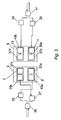
- the wireless optical duplex communication system uses two-element transceivers each of which are connected to an optical transceiver 3 and 5, a modulator 23 and 25, a demodulator 27 and 29 and a converter 39 and 41.
- the combination of optical transceiver, modulator, demodulator and converter is referred to as a semi-set.
- the first 3 and second 5 optical transceivers are located facing each other at the opposite ends of the optical communication line formed therebetween.
- the converters 39 and 41 are connected to the digital information exchange network (transmission and reception) (not shown).
- the input information comes to a converter 39 of the first semi-set connected to the first optical transceiver 3, where it is coded utilising Manchester-type code.
- the input information is then fed at pre-defined logical levels to Modulator 23 which controls the emission of LED 43a which is part of the optical transmitter (optical emitter) 9 in such a way that during transmission of logical "1" light pulses are emitted in the first half of the given clock interval, and during transmission of logical "0" light pulses are transmitted in the second half of the given clock interval.
- the signal emitted by LED 43a comes to optical condenser 37a of the first optical transmitter 9.
- the optical condenser 37a forms the beam angle of the optical transmitter 9(optical emitter) to be between 30 and 60 angular minutes.
- the LED emits infra-red radiation containing a range of wavelengths typically between 820 and 870 nm.
- the radiation absorption characteristics in the transmission path of the optical emitter vary depending on atmospheric conditions.
- the use of a radiation emitter that emits a range of wavelengths ensures that at least some of the radiation reaches the receiver without being absorbed by the atmosphere irrespective of the atmospheric conditions.
- larger wavelength ranges can be used in the infra-red region or other parts of the electromagnetic spectrum.
- Manchester-type coding is used, because it ensures resistance to impulse noise and reduces the probability of false alarms at the signal/noise ratios found in devices of this type.
- the leading edge of the signal is used for coding unities and zeros.
- the bit period time to transmit one bit of data
- Information is coded by potential differences happening in the middle of each bit period.
- a unity is coded by a change from the low level to the high one, and zero by the reverse change.
- At the beginning of each bit period there may be a service signal drop, if several unities or zeros are to be transmitted. Since the signal is changed at least once per bit period such a code possesses good self-synchronizing qualities and advantageously, allows the use of two signal levels for data transmission.
- the optical radiation of the first optical transmitter 9 of the first transceiver 3 irradiates the optical condenser 37c of the first optical receiver 15 of the second transceiver 5, see beam A in Fig. 1).
- the optical energy collected by the optical condenser 37c of the first optical receiver 13 of the second transceiver 5 is directed through a stop or diaphragm aperture 45 (Fig.5) to a photodiode 35a. Thereafter, it is transformed into an electric signal, and then directed to demodulator 29.
- the optical condenser of the optical receiver 35 forms an angular beam of between 30 and 60 angular minutes.
- the signal is transformed into logical levels of the Manchester-type code and is fed to converter 41 where it is transformed into an information signal in accordance with the requirements of the network protocols and directed to the information transmission digital network.
- the spacing of the optical devices creates a separate route of beam transmission for each channel of the duplex communication line (beam A, beam B in Fig. 1).
- beam A, beam B in Fig. 1 The probability of simultaneous emergence of conditions for the maximum beam deviation in both routes of transmission, and, thus, the probability of a simultaneous communication failure in both channels, is reduced as compared to the case of transmission along a common route.
- the present invention with two-element transceivers using two routes (two communication channels) of beam transmission (beams A, B in Fig. 1) provides for integral summation of signals by two spaced beam transmission routes.
- the integral summation thus formed in the communication system realizes the information transmission, reception and processing scheme, in which simultaneous failures in both channels are possible only in case of simultaneous communication failures in both beam transmission routes.
- a special optical scheme is used for each of the optical receivers (Fig. 5), in which a diaphragm or stop aperture 45 is installed in the focal plane of the lens 37, forming the visual angle of the optical receiver (the beam angle).
- the optical scheme sets the maximum and minimum beam angle for transmission and, in conjunction with the diaphragm 45, reduces the density of the light flow on the photodiode surface and consequently increases the operation resource of LED.
- the beam angle of optical transmitters and receivers is standardized. Allowable values of the beam angle of the optical transmitters and receivers are limited to maximum and minimum values and are selected using the above equation to be between 30 and 60 angular minutes in this example.
- an infra-red beam having a frequency of 340000 GHz and wavelength of 850 nm is created having a beam diameter of 10m at a distance of 1.5Km from its source.
- the minimum value of the beam angle is a practical limit which ensures the absence of communication failures in case of an error of mutual angular pointing caused by deformations and slow vibrations of buildings or position errors and change of the angle of arrival of the light beam to the aperture of the optical receiver when the beam passes through turbulent atmosphere.
- the maximum beam angle value is set to provide sufficient power in the communications line to allow effective communication.
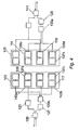
- each consisting of the first optical transmitter 109, the first optical receiver 107, the second optical transmitter 117, and the second optical receiver 119 are located as shown in Fig. 2 and are similar to the optical transmitters and optical receivers of the two-element transceivers 3, 5.
- the information transmission process is as follows, and, since the system is duplex and the operations of information transmission from one transceiver to the other are the same in both directions, the information transmission process will be described with reference to the communication channel from the first transceiver 103 to the second transceiver 105 (Fig. 2, 4).
- the information comes to converter 139 of the first optical transceiver 103, where it is coded using the Manchester-type code and then fed to Modulator M1 123 of first optical transceiver 103 to control emission of LED 143a and 143b of the first and second optical transmitters 109 and 117 through respective optical condensers 137a, 137c in such a way that during transmission of logical "1" light impulses are emitted in the first half of the given clock interval, and during transmission of logical "0" light impulses are transmitted in the second half.
- Optical condensers 137a and 137c of the first and second optical transmitters 109 and 117 are a way that during transmission of logical "1" light impulses are emitted in the first half of the given clock interval, and during transmission of logical "0" light impulses are transmitted in the second half.
- each optical transmitter optical emitter
- Manchester-type coding is used as shown above, because it ensures resistance to impulse noise and reduces the probability of false alarm.
- the optical radiation of each of the optical transmitters 109 and 117 irradiates optical condensers 137b and 137d of the first and second optical receivers 111 and 119 of the second optical transceiver 105(beams C,D,E and F in Fig.2).
- the optical energy collected by the optical condensers 37 (fig.5) is directed through the respective diaphragm apertures 45 to respective photodiodes 35, transformed into electric signals summed later in electronic summator ⁇ 2 133 of the second optical transceiver 105.
- the summator implements the information transmission and processing scheme. A failure of information transmission through the communication channel is possible only where a simultaneous failure in all four beam spreading routes has occured.
- demodulator 129 of the second optical transceiver 105 the signal from the ⁇ 2 summator 133a output is transformed into the logical levels of the Manchester-type code and fed to converter K2 of the second optical transceiver 105, where it is transformed into signals meeting the network protocol requirements and channeled to the digital information (consumer) network.
- the four-element information transmission and reception system as a whole (two transceivers and four respective transmitters and four receivers), its realization allows for the formation of an integral summing system (since summation due to the beam transmission geometry shown in Fig. 2 is made in each communication channel: optical transmitter - optical receiver), which embodies the information transmission and processing system, where a simultaneous failure in all the channels is possible only in case of simultaneous failures in eight beam transmission routes (beams C, D, E, F. G. H, I and J in Fig. 2).
- the present invention incorporates a data confirmation routine in which confirmation that data has been received at a transceiver is provided by sending a separate data stream in the opposite direction in a different vector space. This is achieved by attaching a characteristic group of symbols to the data packet. The receipt of these symbols is acknowledged by the transmission of an acknowledgement to the data packet transmitter. Where receipt of the data packet has not been acknowledged, transmission of the original data package will be repeated.
- Beam angle selection makes it possible to prevent communication failures in case of a mutual angular pointing error where the necessary energy potential in the communication line is available. Spacing of the optical transmitters and receivers at each end (point) of the communication line reduces the probability of failures, when the line is crossed by nontransparent objects.
- the use of a special optical receiver circuit helps reduce the density of the light flow on the photodiode surface and increases the LED operation resource.
- Incoherent light sources use LEDs as incoherent light sources.
- Incoherent light sources have a number of advantages over laser (or coherent) sources for use in communications systems.
- the radiation spectrum width of a laser is many times smaller than that of an incoherent light source and the spectral emission width in the atmosphere can correspond to the typical laser radiation spectrum width. Therefore attenuation of the laser beam by atmospheric conditions can be severe.
- the larger spectrum width of the incoherent light source greatly decreases the likelihood of high attenuation. Therefore, in laser communications systems (depending upon the temperature of the laser, where the wavelength depends upon temperature) attenuation values can exist that correspond to maximum atmospheric spectral emission values, whereas in incoherent systems, such as LED systems, the much larger spectrum width obviates this problem.
- LEDs are much cheaper than lasers to manufacture and unlike lasers, are safe even for personnel located in close proximity to the optical transmitters (emitters).
- high power lasers are used to increase the range over which a communications system can operate, there is an increased health risk to people caught in the beam path. There is no associated health risk with incoherent or LED systems.
- incoherent light sources means that interference between signals in the present invention is minimised.
- the apparatus in accordance with the present invention can have an optical path length of 3000m.
Landscapes
- Physics & Mathematics (AREA)
- Electromagnetism (AREA)
- Engineering & Computer Science (AREA)
- Computer Networks & Wireless Communication (AREA)
- Signal Processing (AREA)
- Optical Communication System (AREA)
Claims (10)
- Appareil pour communication duplex sans fil, comprenant un premier émetteur récepteur optique (3) ayant un premier émetteur optique (9) et un premier récepteur optique (7), un deuxième émetteur récepteur optique (5) ayant un premier émetteur optique (13) et un premier récepteur optique (11), les premier et deuxième émetteurs récepteurs (3, 5) étant situés à des extrémités opposées d'une ligne de communication optique constituée de ceux-ci, dans lequel la sortie de chacun des émetteurs optiques (9, 13) est un faisceau divergent de rayonnement électromagnétique incohérent agencé pour avoir un diamètre de coupe transversale qui est plus grand que le diamètre de coupe transversale du récepteur optique respectif (7, 11) au point de la ligne de communication auquel le récepteur optique respectif (7, 11) est situé, dans lequel chacun des récepteurs optiques (7, 11) comprend une lentille de condensateur optique (37) ayant un plan focal, une photodiode (35), et un diaphragme (45) ayant une ouverture et situé dans le plan focal de la lentille de condensateur optique (37) entre la lentille de condensateur optique (37) et la photodiode (35), dans lequel la distance Δ entre le diaphragme (45) et la photodiode (35) est définie par Δ = b F / Dc, où b est le diamètre d'un site sensible à la lumière de la photodiode (35), Dc est le diamètre de la lentille de condensateur optique (37), et F est la distance focale de la lentille de condensateur optique (37), et dans lequel un angle de faisceau θ caractérisant les premiers émetteurs (9, 13) et les premiers récepteurs (7, 11) est défini par Tan 2θ = a / F, où a est l'ouverture du diaphragme (45).
- Appareil selon la revendication 1, dans lequel chacun des premiers émetteurs optiques (9, 13) émet un rayonnement électromagnétique dans la plage de 800 à 900 nanomètres.
- Appareil selon la revendication 1 ou 2, dans lequel chacun des premiers émetteurs optiques (9, 13) comprend une diode électroluminescente (DEL) fournissant une source du faisceau divergent de rayonnement électromagnétique incohérent, et comprend en outre au moins une lentille de condensateur optique, l'entrée de la lentille de condensateur optique étant assurée par la DEL et la sortie de l'émetteur optique (9, 13) étant assurée par la lentille de condensateur optique.
- Appareil selon l'une quelconque des revendications précédentes, dans lequel une entrée de la lentille de condensateur optique (37) est une entrée de l'un des premiers récepteurs optiques (7, 11), et une sortie de la photodiode (35) est une sortie de l'un des premiers récepteurs optiques (7, 11).
- Appareil selon l'une quelconque des revendications précédentes, dans lequel l'angle de faisceau θ est entre 30 et 60 minutes angulaires.
- Appareil selon l'une quelconque des revendications précédentes, dans lequel la distance entre les premiers émetteurs optiques (9, 13) et les premiers récepteurs optiques (7, 11) de chacun des premier et deuxième émetteurs récepteurs (3, 5) est supérieure ou égale à d/2, où d = 30 cm.
- Appareil selon l'une quelconque des revendications précédentes, dans lequel une entrée du premier émetteur optique (9) du premier émetteur récepteur (3) est connectée à une sortie d'un premier convertisseur (39) à travers un premier modulateur (23), et une sortie du premier récepteur optique (7) du premier émetteur récepteur (3) est connectée à une entrée d'un premier démodulateur (27), dont la sortie est connectée à une entrée du premier convertisseur (39) ; et une entrée du premier émetteur optique (13) du deuxième émetteur récepteur (5) est connectée à une sortie d'un deuxième convertisseur (41) à travers un modulateur (25), et une sortie du premier récepteur optique (11) du deuxième émetteur récepteur (5) est connectée à une entrée d'un deuxième démodulateur (29), dont la sortie est connectée à l'entrée du deuxième convertisseur (41).
- Appareil selon la revendication 7, dans lequel les premier et deuxième convertisseurs (39, 41) sont chacun constitués sous la forme d'un transformateur, dans lequel chacun des premier et deuxième convertisseurs (39, 41) transforme des signaux d'informations discrètes d'entrée en un signal codé en utilisant le code de Manchester pendant la transmission, et dans lequel chacun des premier et deuxième convertisseurs (39, 41) est capable d'effectuer une transformation inverse de signaux provenant des sorties des démodulateurs respectifs (27, 29) pendant la réception.
- Appareil selon l'une quelconque des revendications précédentes, dans lequel chacun des premier et deuxième émetteurs récepteurs optiques (3, 5) comprend en outre un deuxième émetteur optique (117) et un deuxième récepteur optique (111) .
- Appareil selon la revendication 9, dans lequel chacun des premier et deuxième émetteurs récepteurs (3, 5) comprend en outre un sommateur (133a, 133b) et un démodulateur (127, 129) ayant une entrée, et dans lequel les premier et deuxième récepteurs optiques (7, 11, 111) dans chaque émetteur récepteur optique (3, 5) sont connectés à l'entrée du démodulateur respectif (127, 129) à travers le sommateur (133).
Applications Claiming Priority (3)
| Application Number | Priority Date | Filing Date | Title |
|---|---|---|---|
| RU2001105766/09A RU2178954C1 (ru) | 2001-03-01 | 2001-03-01 | Беспроводная дуплексная оптическая система связи |
| RU2001105766 | 2001-03-01 | ||
| PCT/GB2002/000674 WO2002071656A2 (fr) | 2001-03-01 | 2002-02-13 | Systeme de communication optique sans fil en duplex |
Publications (2)
| Publication Number | Publication Date |
|---|---|
| EP1413073A2 EP1413073A2 (fr) | 2004-04-28 |
| EP1413073B1 true EP1413073B1 (fr) | 2008-01-02 |
Family
ID=20246707
Family Applications (1)
| Application Number | Title | Priority Date | Filing Date |
|---|---|---|---|
| EP02711101A Expired - Lifetime EP1413073B1 (fr) | 2001-03-01 | 2002-02-13 | Systeme de communication optique sans fil en duplex |
Country Status (12)
| Country | Link |
|---|---|
| US (1) | US7369775B2 (fr) |
| EP (1) | EP1413073B1 (fr) |
| AT (1) | ATE382997T1 (fr) |
| CA (1) | CA2439369A1 (fr) |
| DE (1) | DE60224399T2 (fr) |
| GB (1) | GB2377570A (fr) |
| IL (1) | IL160244A0 (fr) |
| MX (1) | MXPA03007872A (fr) |
| NZ (1) | NZ531361A (fr) |
| RU (1) | RU2178954C1 (fr) |
| WO (2) | WO2002071655A2 (fr) |
| ZA (1) | ZA200309183B (fr) |
Families Citing this family (23)
| Publication number | Priority date | Publication date | Assignee | Title |
|---|---|---|---|---|
| US7146105B1 (en) * | 2002-04-12 | 2006-12-05 | Paul Tzeng | MEMS-based optical wireless communication system |
| RU2226036C1 (ru) * | 2002-06-27 | 2004-03-20 | Самарский государственный аэрокосмический университет им. акад. С.П. Королева | Устройство оптического соединения для многопроцессорной вычислительной системы |
| US7106973B2 (en) * | 2002-08-13 | 2006-09-12 | Lightpointe Communications, Inc. | Apparatus and method for use in free-space optical communication comprising optically aligned components integrated on circuit boards |
| RU2246177C2 (ru) * | 2002-11-19 | 2005-02-10 | Майер Александр Александрович | Способ передачи информации в системах оптической связи (варианты) |
| US7120363B2 (en) * | 2002-12-20 | 2006-10-10 | Lightpointe Communications, Inc. | Method and apparatus for maintaining optical alignment for free-space optical communication |
| US20040141753A1 (en) * | 2003-01-21 | 2004-07-22 | Lightpointe Communications, Inc. | Apparatus and method for tracking in free-space optical communication systems |
| WO2004106978A2 (fr) * | 2003-05-31 | 2004-12-09 | Lumenlink, Co., Ltd | Procede de mise en boitier pour la fabrication d'un emetteur / recepteur optique dans un systeme optique de communication sans fil |
| KR100800365B1 (ko) * | 2005-11-28 | 2008-02-04 | (주)루멘링크 | 무선 광통신용 송신기와 수신기 제작을 위한 패키징 방법 |
| RU2304846C1 (ru) * | 2005-12-08 | 2007-08-20 | Общество с ограниченной ответственностью "СитиЛинк" | Способ приема-передачи информации и устройство для приема-передачи информации |
| RU2313180C2 (ru) * | 2005-12-30 | 2007-12-20 | Общество с ограниченной ответственностью "Компания "Проксима" | Способ приема-передачи информации и устройство для приема-передачи информации |
| RU2328077C1 (ru) * | 2006-11-30 | 2008-06-27 | Федеральное Государственное Унитарное Предприятие "Государственный Рязанский Приборный Завод" | Устройство двухсторонней оптической связи |
| US7400801B1 (en) | 2007-06-19 | 2008-07-15 | Owlink Technology, Inc. | Bidirectional HDCP module using single optical fiber and waveguide combiner/splitter |
| WO2009096927A1 (fr) * | 2008-01-31 | 2009-08-06 | Hewlett-Packard Development Company, L.P. | Interconnexion optique en espace libre |
| RU2407168C1 (ru) * | 2009-07-09 | 2010-12-20 | Федеральное государственное учреждение 16 Центральный научно-исследовательский испытательный институт Министерства обороны Российской Федерации имени маршала войск связи А.И. Белова | Приемопередатчик волоконно-оптической линии связи |
| RU2459271C2 (ru) * | 2010-05-17 | 2012-08-20 | Федеральное государственное образовательное учреждение высшего профессионального образования "Военный авиационный инженерный университет" (г. Воронеж) Министерства обороны Российской Федерации | Способ многоканальной передачи оптических сигналов |
| TWI467935B (zh) * | 2012-03-06 | 2015-01-01 | Ind Tech Res Inst | 可見光通訊收發器與系統 |
| TWI467937B (zh) * | 2012-06-08 | 2015-01-01 | Univ Nat Chiao Tung | 可降低背景光雜訊之發光二極體通訊裝置 |
| US10291329B2 (en) * | 2013-12-20 | 2019-05-14 | Infineon Technologies Ag | Exchanging information between time-of-flight ranging devices |
| KR20160110432A (ko) * | 2014-01-10 | 2016-09-21 | 팔머 랩스, 엘엘씨 | 발산-광선 통신 시스템 |
| CN105929493A (zh) * | 2016-06-24 | 2016-09-07 | 中国人民解放军信息工程大学 | 可见光接收端的调整方法及相关设备 |
| US10057672B2 (en) | 2016-10-04 | 2018-08-21 | Nxp B.V. | Optical communication interface |
| WO2022123604A1 (fr) * | 2020-12-10 | 2022-06-16 | Lightspeedai Labs Private Limited | Système et procédé pour permettre des canaux optiques pour une communication à grande vitesse |
| CN217656691U (zh) * | 2022-06-20 | 2022-10-25 | 中强光电股份有限公司 | 投影装置 |
Family Cites Families (26)
| Publication number | Priority date | Publication date | Assignee | Title |
|---|---|---|---|---|
| US4056719A (en) | 1975-02-10 | 1977-11-01 | Bell Telephone Laboratories, Incorporated | Two-way telephone transmission system utilizing opto-couplers |
| RU2030834C1 (ru) * | 1986-08-22 | 1995-03-10 | Нижегородский научно-исследовательский институт радиотехники | Световодная система передачи аналоговой информации |
| US4977618A (en) | 1988-04-21 | 1990-12-11 | Photonics Corporation | Infrared data communications |
| US5060303A (en) * | 1988-09-06 | 1991-10-22 | Wilmoth Thomas E | Optical data link system, and methods of constructing and utilizing same |
| JPH03108823A (ja) * | 1989-09-21 | 1991-05-09 | Opt:Kk | 光通信装置 |
| JPH0671266B2 (ja) | 1990-06-01 | 1994-09-07 | 日本航空電子工業株式会社 | 光トランシーバ |
| CA2122644C (fr) | 1990-06-22 | 1997-09-09 | Takeo Kaharu | Methode de transmission par bus a fibres optiques avec codeur pour l'emission et decodeur pour la reception |
| EP0548409B1 (fr) | 1991-12-23 | 1997-12-29 | Alcatel | Système de transmission optique |
| JP3187495B2 (ja) * | 1991-12-28 | 2001-07-11 | ソニー株式会社 | 光空間伝送装置 |
| US5359446A (en) * | 1992-09-10 | 1994-10-25 | Eldec Corporation | Wide-angle, high-speed, free-space optical communications system |
| US5532858A (en) * | 1992-10-16 | 1996-07-02 | Nit Data Communications Victor Company Of Japan | Optical radio transmission system and a method for adjusting optical axes thereof |
| US5345327A (en) | 1993-03-29 | 1994-09-06 | At&T Bell Laboratories | Digital infrared communications system with edge detection |
| JP3302141B2 (ja) * | 1993-11-16 | 2002-07-15 | キヤノン株式会社 | 光空間通信方法 |
| JPH07177092A (ja) * | 1993-12-16 | 1995-07-14 | Kokusai Electric Co Ltd | 光受信機 |
| JPH07235907A (ja) * | 1993-12-29 | 1995-09-05 | Sony Corp | 光空間伝送装置 |
| GB9401643D0 (en) * | 1994-01-28 | 1994-03-23 | Lee Communications Ltd | Data transmission system |
| US5495357A (en) * | 1994-02-14 | 1996-02-27 | Machina, Inc. | Apparatus and method for recording, transmitting, receiving and playing sounds |
| KR100242408B1 (ko) | 1994-04-18 | 2000-02-01 | 포만 제프리 엘 | 무선 광 통신 시스템 및 방법과 그에 사용되는 수신 유닛 |
| EP0783808B1 (fr) | 1994-09-03 | 2000-08-02 | International Business Machines Corporation | Modules emetteur et emetteur-recepteur optiques de transmission de donnees sans fil |
| EP0849896B1 (fr) | 1994-09-03 | 2001-03-07 | International Business Machines Corporation | Module émetteur-récepteur pour transmission de données sans fil |
| US5546211A (en) * | 1995-06-13 | 1996-08-13 | Apple Computer, Inc. | Method and apparatus for multi-protocol infrared data transmission |
| RU2121229C1 (ru) * | 1995-09-12 | 1998-10-27 | Товарищество с ограниченной ответственностью Предприятие "А. & П" | Оптическая система связи |
| JP3701396B2 (ja) * | 1996-07-03 | 2005-09-28 | 株式会社エルテル | 光空間伝送方法と装置 |
| DE19715636A1 (de) | 1997-04-15 | 1998-10-22 | Renfer Robert O | Vorrichtung zur drahtlosen optischen Übertragung |
| CA2314956A1 (fr) | 1997-12-17 | 1999-06-24 | Yaron Ruziack | Liaison de communications reseau |
| US6256296B1 (en) * | 1997-12-17 | 2001-07-03 | Yaron Ruziak | Network communications link |
-
2001
- 2001-03-01 RU RU2001105766/09A patent/RU2178954C1/ru not_active IP Right Cessation
-
2002
- 2002-01-14 WO PCT/GB2002/000139 patent/WO2002071655A2/fr not_active Ceased
- 2002-02-13 CA CA002439369A patent/CA2439369A1/fr not_active Abandoned
- 2002-02-13 EP EP02711101A patent/EP1413073B1/fr not_active Expired - Lifetime
- 2002-02-13 IL IL16024402A patent/IL160244A0/xx unknown
- 2002-02-13 AT AT02711101T patent/ATE382997T1/de not_active IP Right Cessation
- 2002-02-13 WO PCT/GB2002/000674 patent/WO2002071656A2/fr not_active Ceased
- 2002-02-13 DE DE60224399T patent/DE60224399T2/de not_active Expired - Lifetime
- 2002-02-13 GB GB0203337A patent/GB2377570A/en not_active Withdrawn
- 2002-02-13 NZ NZ531361A patent/NZ531361A/en active Application Filing
- 2002-02-13 MX MXPA03007872A patent/MXPA03007872A/es unknown
- 2002-02-27 US US10/083,491 patent/US7369775B2/en not_active Expired - Fee Related
-
2003
- 2003-11-26 ZA ZA200309183A patent/ZA200309183B/en unknown
Also Published As
| Publication number | Publication date |
|---|---|
| US20020126340A1 (en) | 2002-09-12 |
| WO2002071655A2 (fr) | 2002-09-12 |
| GB0203337D0 (en) | 2002-03-27 |
| IL160244A0 (en) | 2004-07-25 |
| WO2002071656A3 (fr) | 2003-09-04 |
| MXPA03007872A (es) | 2005-10-19 |
| GB2377570A (en) | 2003-01-15 |
| CA2439369A1 (fr) | 2002-09-12 |
| EP1413073A2 (fr) | 2004-04-28 |
| US7369775B2 (en) | 2008-05-06 |
| RU2178954C1 (ru) | 2002-01-27 |
| WO2002071656A2 (fr) | 2002-09-12 |
| NZ531361A (en) | 2006-11-30 |
| ZA200309183B (en) | 2004-12-07 |
| ATE382997T1 (de) | 2008-01-15 |
| DE60224399D1 (de) | 2008-02-14 |
| DE60224399T2 (de) | 2008-12-18 |
Similar Documents
| Publication | Publication Date | Title |
|---|---|---|
| US7369775B2 (en) | Wireless duplex optical communication system | |
| US4493114A (en) | Optical non-line-of-sight covert, secure high data communication system | |
| EP0748542B1 (fr) | Procede et appareil de communications optiques sans cable | |
| US4977618A (en) | Infrared data communications | |
| US5959752A (en) | Optical transceiver and optical communications network for both of optical fiber transmission and free space transmission | |
| EP3055937B1 (fr) | Système de communication sous-marin à grande portée | |
| JPH09508249A (ja) | 適応データ速度及び/又は適応光パワーレベルを有するワイヤレス光通信システム | |
| Bhowal et al. | Transmit laser selection for two hop decode and forward FSO communication with pointing errors | |
| Sharma et al. | Literature survey and issue on free space optical communication system | |
| AU2002229992A1 (en) | Wireless duplex optical communication system | |
| Andrews et al. | Free-space optical communication link and atmospheric effects: single aperture and arrays | |
| Deka et al. | Performance analysis of DF based cascaded VLC-FSO-VLC system | |
| JP2002084232A (ja) | 空中光通信のための方法および送受信機 | |
| Nandi et al. | Study of variation of Q-factor using minimum power under different weather conditions | |
| CN119602875B (zh) | 一种基于反射面的可见光通信空间调制方法 | |
| RU2774409C1 (ru) | Способ повышения помехоустойчивости передачи данных по коротковолновому радиоканалу в ведомственной системе связи | |
| Patel et al. | Exploring Challenges in Modern High Speed Free Space Optical Communication | |
| Androutsos et al. | Influence of Pointing Errors at the Block Error Rate Performance of Strong Turbulent SIMO FSO Links | |
| Singha et al. | Performance analysis of dual-hop Double Generalized Gamma (DGG) and Málaga distributed FSO network | |
| Abaza | Cooperative MIMO techniques for outdoor optical wireless communication systems | |
| AT407934B (de) | Übertragungssystem mit transponder | |
| JPH10322276A (ja) | 空間光伝送装置 | |
| Kwok et al. | Receiver sensitivity improvement of optical wireless channels with delayed-diversified pulse-position modulation | |
| Choudhary et al. | Study of trellis coded overlapping ppm and overlapping multi-pulse ppm schemes for deep space optical communication systems | |
| Jh | Performance analysis of free space optical communication system in the presence of physical limitations |
Legal Events
| Date | Code | Title | Description |
|---|---|---|---|
| PUAI | Public reference made under article 153(3) epc to a published international application that has entered the european phase |
Free format text: ORIGINAL CODE: 0009012 |
|
| 17P | Request for examination filed |
Effective date: 20040220 |
|
| AK | Designated contracting states |
Kind code of ref document: A2 Designated state(s): AT BE CH CY DE DK ES FI FR GB GR IE IT LI LU MC NL PT SE TR |
|
| AX | Request for extension of the european patent |
Extension state: AL LT LV MK RO SI |
|
| RAP1 | Party data changed (applicant data changed or rights of an application transferred) |
Owner name: FREEWIRE COMMUNICATIONS LTD. |
|
| GRAP | Despatch of communication of intention to grant a patent |
Free format text: ORIGINAL CODE: EPIDOSNIGR1 |
|
| GRAS | Grant fee paid |
Free format text: ORIGINAL CODE: EPIDOSNIGR3 |
|
| GRAA | (expected) grant |
Free format text: ORIGINAL CODE: 0009210 |
|
| AK | Designated contracting states |
Kind code of ref document: B1 Designated state(s): AT BE CH CY DE DK ES FI FR GB GR IE IT LI LU MC NL PT SE TR |
|
| REG | Reference to a national code |
Ref country code: GB Ref legal event code: FG4D |
|
| REG | Reference to a national code |
Ref country code: IE Ref legal event code: FG4D |
|
| REG | Reference to a national code |
Ref country code: CH Ref legal event code: EP |
|
| REF | Corresponds to: |
Ref document number: 60224399 Country of ref document: DE Date of ref document: 20080214 Kind code of ref document: P |
|
| RAP2 | Party data changed (patent owner data changed or rights of a patent transferred) |
Owner name: MA LING LTD |
|
| PG25 | Lapsed in a contracting state [announced via postgrant information from national office to epo] |
Ref country code: NL Free format text: LAPSE BECAUSE OF FAILURE TO SUBMIT A TRANSLATION OF THE DESCRIPTION OR TO PAY THE FEE WITHIN THE PRESCRIBED TIME-LIMIT Effective date: 20080102 |
|
| NLV1 | Nl: lapsed or annulled due to failure to fulfill the requirements of art. 29p and 29m of the patents act | ||
| PG25 | Lapsed in a contracting state [announced via postgrant information from national office to epo] |
Ref country code: ES Free format text: LAPSE BECAUSE OF FAILURE TO SUBMIT A TRANSLATION OF THE DESCRIPTION OR TO PAY THE FEE WITHIN THE PRESCRIBED TIME-LIMIT Effective date: 20080413 Ref country code: LI Free format text: LAPSE BECAUSE OF FAILURE TO SUBMIT A TRANSLATION OF THE DESCRIPTION OR TO PAY THE FEE WITHIN THE PRESCRIBED TIME-LIMIT Effective date: 20080102 Ref country code: FI Free format text: LAPSE BECAUSE OF FAILURE TO SUBMIT A TRANSLATION OF THE DESCRIPTION OR TO PAY THE FEE WITHIN THE PRESCRIBED TIME-LIMIT Effective date: 20080102 Ref country code: CH Free format text: LAPSE BECAUSE OF FAILURE TO SUBMIT A TRANSLATION OF THE DESCRIPTION OR TO PAY THE FEE WITHIN THE PRESCRIBED TIME-LIMIT Effective date: 20080102 |
|
| REG | Reference to a national code |
Ref country code: CH Ref legal event code: PL |
|
| PG25 | Lapsed in a contracting state [announced via postgrant information from national office to epo] |
Ref country code: AT Free format text: LAPSE BECAUSE OF FAILURE TO SUBMIT A TRANSLATION OF THE DESCRIPTION OR TO PAY THE FEE WITHIN THE PRESCRIBED TIME-LIMIT Effective date: 20080102 |
|
| ET | Fr: translation filed | ||
| PG25 | Lapsed in a contracting state [announced via postgrant information from national office to epo] |
Ref country code: BE Free format text: LAPSE BECAUSE OF FAILURE TO SUBMIT A TRANSLATION OF THE DESCRIPTION OR TO PAY THE FEE WITHIN THE PRESCRIBED TIME-LIMIT Effective date: 20080102 Ref country code: PT Free format text: LAPSE BECAUSE OF FAILURE TO SUBMIT A TRANSLATION OF THE DESCRIPTION OR TO PAY THE FEE WITHIN THE PRESCRIBED TIME-LIMIT Effective date: 20080602 |
|
| PG25 | Lapsed in a contracting state [announced via postgrant information from national office to epo] |
Ref country code: DK Free format text: LAPSE BECAUSE OF FAILURE TO SUBMIT A TRANSLATION OF THE DESCRIPTION OR TO PAY THE FEE WITHIN THE PRESCRIBED TIME-LIMIT Effective date: 20080102 Ref country code: SE Free format text: LAPSE BECAUSE OF FAILURE TO SUBMIT A TRANSLATION OF THE DESCRIPTION OR TO PAY THE FEE WITHIN THE PRESCRIBED TIME-LIMIT Effective date: 20080402 Ref country code: MC Free format text: LAPSE BECAUSE OF NON-PAYMENT OF DUE FEES Effective date: 20080228 |
|
| PLBE | No opposition filed within time limit |
Free format text: ORIGINAL CODE: 0009261 |
|
| STAA | Information on the status of an ep patent application or granted ep patent |
Free format text: STATUS: NO OPPOSITION FILED WITHIN TIME LIMIT |
|
| 26N | No opposition filed |
Effective date: 20081003 |
|
| PG25 | Lapsed in a contracting state [announced via postgrant information from national office to epo] |
Ref country code: IE Free format text: LAPSE BECAUSE OF NON-PAYMENT OF DUE FEES Effective date: 20080213 |
|
| PG25 | Lapsed in a contracting state [announced via postgrant information from national office to epo] |
Ref country code: CY Free format text: LAPSE BECAUSE OF FAILURE TO SUBMIT A TRANSLATION OF THE DESCRIPTION OR TO PAY THE FEE WITHIN THE PRESCRIBED TIME-LIMIT Effective date: 20080102 |
|
| PG25 | Lapsed in a contracting state [announced via postgrant information from national office to epo] |
Ref country code: IT Free format text: LAPSE BECAUSE OF FAILURE TO SUBMIT A TRANSLATION OF THE DESCRIPTION OR TO PAY THE FEE WITHIN THE PRESCRIBED TIME-LIMIT Effective date: 20080102 |
|
| PGFP | Annual fee paid to national office [announced via postgrant information from national office to epo] |
Ref country code: FR Payment date: 20100315 Year of fee payment: 9 |
|
| PGFP | Annual fee paid to national office [announced via postgrant information from national office to epo] |
Ref country code: DE Payment date: 20100208 Year of fee payment: 9 Ref country code: GB Payment date: 20100219 Year of fee payment: 9 |
|
| PG25 | Lapsed in a contracting state [announced via postgrant information from national office to epo] |
Ref country code: LU Free format text: LAPSE BECAUSE OF NON-PAYMENT OF DUE FEES Effective date: 20080213 |
|
| PG25 | Lapsed in a contracting state [announced via postgrant information from national office to epo] |
Ref country code: TR Free format text: LAPSE BECAUSE OF FAILURE TO SUBMIT A TRANSLATION OF THE DESCRIPTION OR TO PAY THE FEE WITHIN THE PRESCRIBED TIME-LIMIT Effective date: 20080102 |
|
| PG25 | Lapsed in a contracting state [announced via postgrant information from national office to epo] |
Ref country code: GR Free format text: LAPSE BECAUSE OF FAILURE TO SUBMIT A TRANSLATION OF THE DESCRIPTION OR TO PAY THE FEE WITHIN THE PRESCRIBED TIME-LIMIT Effective date: 20080403 |
|
| GBPC | Gb: european patent ceased through non-payment of renewal fee |
Effective date: 20110213 |
|
| REG | Reference to a national code |
Ref country code: FR Ref legal event code: ST Effective date: 20111102 |
|
| REG | Reference to a national code |
Ref country code: DE Ref legal event code: R119 Ref document number: 60224399 Country of ref document: DE Effective date: 20110901 |
|
| PG25 | Lapsed in a contracting state [announced via postgrant information from national office to epo] |
Ref country code: FR Free format text: LAPSE BECAUSE OF NON-PAYMENT OF DUE FEES Effective date: 20110228 |
|
| PG25 | Lapsed in a contracting state [announced via postgrant information from national office to epo] |
Ref country code: GB Free format text: LAPSE BECAUSE OF NON-PAYMENT OF DUE FEES Effective date: 20110213 |
|
| PG25 | Lapsed in a contracting state [announced via postgrant information from national office to epo] |
Ref country code: DE Free format text: LAPSE BECAUSE OF NON-PAYMENT OF DUE FEES Effective date: 20110901 |