EP1413233B1 - Wäschebügel, insbesondere für String-Tanga - Google Patents
Wäschebügel, insbesondere für String-Tanga Download PDFInfo
- Publication number
- EP1413233B1 EP1413233B1 EP03024160A EP03024160A EP1413233B1 EP 1413233 B1 EP1413233 B1 EP 1413233B1 EP 03024160 A EP03024160 A EP 03024160A EP 03024160 A EP03024160 A EP 03024160A EP 1413233 B1 EP1413233 B1 EP 1413233B1
- Authority
- EP
- European Patent Office
- Prior art keywords
- connecting member
- hanger
- undergarment
- hanger according
- web
- Prior art date
- Legal status (The legal status is an assumption and is not a legal conclusion. Google has not performed a legal analysis and makes no representation as to the accuracy of the status listed.)
- Expired - Lifetime
Links
- 239000000725 suspension Substances 0.000 claims 1
- 210000002105 tongue Anatomy 0.000 description 24
- 239000004744 fabric Substances 0.000 description 4
- 238000010409 ironing Methods 0.000 description 2
- 239000000463 material Substances 0.000 description 2
- 230000003014 reinforcing effect Effects 0.000 description 2
- 238000009825 accumulation Methods 0.000 description 1
- 238000005452 bending Methods 0.000 description 1
- 238000001816 cooling Methods 0.000 description 1
- 230000001419 dependent effect Effects 0.000 description 1
- 238000001746 injection moulding Methods 0.000 description 1
- 230000037431 insertion Effects 0.000 description 1
- 238000003780 insertion Methods 0.000 description 1
- 238000005507 spraying Methods 0.000 description 1
Images

Classifications
-
- A—HUMAN NECESSITIES
- A47—FURNITURE; DOMESTIC ARTICLES OR APPLIANCES; COFFEE MILLS; SPICE MILLS; SUCTION CLEANERS IN GENERAL
- A47G—HOUSEHOLD OR TABLE EQUIPMENT
- A47G25/00—Household implements used in connection with wearing apparel; Dress, hat or umbrella holders
- A47G25/14—Clothing hangers, e.g. suit hangers
- A47G25/48—Hangers with clamps or the like, e.g. for trousers or skirts
Definitions
- the invention relates to a laundry hanger according to the preamble of claim 1, which is intended in particular for receiving underpants, briefs and especially string thongs.
- a laundry hanger is out of the EP 0 925 749 B 1 the applicant known.
- the terminals described here are composed of an abutment part which is stiffened by a web wall of the cross-sectionally double-T-shaped support bracket, and a substantially downwardly directed resilient tongue, which has a U-shaped or 3 ⁇ 4-annular connecting part with the abutment part is resiliently connected.
- the connecting part is more than 50%, preferably 100%, thicker than the thickness of the lower flange or upper flange of the support bracket and is exposed over an angular range of at least 90 °. It has a curvature diameter of at least 6 mm.
- the laundry hanger is made of plastic by injection molding.
- the resilient tongue can open relatively wide, but on the other hand can exert a sufficiently large clamping force, the U-shaped or annular connecting part in cross section is considerably larger than the cross section of the upper flange or lower flange of the double-T-shaped support bracket. Due to the accumulation of material is achieved that when cooling the plastic bracket made by spraying the resilient tongue bears with bias on its abutment.
- the U-shaped or annular connecting part has a relatively large diameter of curvature and is exposed over an angular range of at least 90 °, so that when opening the resilient tongue in this area, the connecting part is bent.
- an opening resistance in the connecting part can be achieved, which can be overcome manually, so that the terminal to equip with a piece of laundry and to remove the laundry with your fingers can be opened.
- the laundry hanger the EP 0 925 749 B1 is designed so that panties and panties are kept very accurate in the laundry hanger.
- an inner guide web is arranged in the interior of the connecting part, which reduces the free space in the interior so that the collar of an inserted into the clamp pants is held substantially perpendicular to the longitudinal extent of the support bracket.
- String thongs are women's underpants or panties, which have ribbon-like waistbands in the side areas. These are held securely in the clamps in the known laundry hanger when the ribbon-like waistbands are pushed into the region of the terminal in which rests the resilient tongue with bias against the abutment.
- the side straps of the thong are often pulled up as far as possible in the clamp. Here they are moved in all known laundry ironing in an area in which the space between the abutment part and the resilient tongue of the clamp is quite large and the side band of the thong does not provide sufficient support.
- Laundry hanger according to the preamble of claim 1 are in the publications US 6,196,430 B1 and US 5,632,423 known.
- resilient fingers are formed on the tongues, which define a gap together with the abutment part. Small projections form a stop at the end of this gap.
- the object of the invention is to provide, starting from the prior art bracket of the Applicant a laundry hanger, the very thin fabrics, as used in string thongs, provides adequate support and is preferably used universally.
- the upper stop of the free space between the tongue and the abutment part can be integrally formed on the tongue, the abutment part or the connecting part between tongue and abutment part in any manner.
- the upper inner side of the connecting part itself forms the upper stop, so that the free space between the abutment part and tongue in the inner region of the connecting part extends in a gap shape.
- the entire space between the abutment part and tongue is gap-shaped. In other embodiments, greater clearance may be left in certain areas below the stopper, for example, to accommodate thicker pants waistbands.
- the gap near the stop is preferably less than 1 mm wide.
- Partly string thongs are used, which have in the page thin silk ribbon. Such silk ribbons are securely held in gaps having a width of the order of 0.1 mm.
- the gap is delimited by at least one guide web projecting into the free space in the interior of the connecting part.
- a guide bar is also known in the bracket of the applicant according to the prior art, but it does not limit reaching up to the top stop narrow gap.
- the guide bar is formed in a practical embodiment of the bracket according to the invention to a stiffened portion of the bent connecting part.
- the non-stiffened portion of the arcuate connecting part is free on its inner side of a guide web and other components so that it is still elastically deformable for bending the terminal.
- the gap is delimited by at least one resilient finger formed on the inside of the connecting part.
- the resilient finger consists of an elongate plastic part, which is integrally connected on one side with a portion of the connecting part.
- the mounting bracket in a practical embodiment is formed in cross-section substantially double-T-shaped and has a web wall, which also stiffen the abutment part and a portion of the bent connecting part.
- the bracket is thus very strong in the vertical direction, and the abutment part of the terminal is very rigid.
- the connecting part is 3 ⁇ 4 ring-shaped and may - as described above - 50 to 100% thicker than the lower chords and upper straps of the double-T-shaped support bracket to a case of a diameter of the connecting part of about 6 mm one for the application suitable biasing force and spring force, which act on the resilient tongue to realize.
- the edge of the guide bar can be wavy.
- the Fig. 1 shows a laundry hanger made of plastic with double-T-shaped cross-section, a web wall 11, a top flange 12 and a bottom flange 13.
- the top flange 12 also encloses the support hooks. 2
- the mounting bracket 1 forms two lying on both sides of the support hook mounting bracket halves 1 a, and 1b. At the outer ends of the two mounting bracket halves 1a and 1b terminals 3 are formed.
- the clamps consist of a rigidly connected to the support bracket 1 abutment part 4 and a resilient tongue 5, which is connected via a 3 ⁇ 4-annular connecting part 6.
- a guide web 8 is arranged in the interior 7 on the stiffened to the support hook 2 region of the connecting part 6.
- the guide web 8 opposite is a resilient finger 9, the lower end of which is integrally formed on the outer end of the annular connecting part 6.
- a narrow gap 10 having a width of about 0.1 mm. At the upper end of this narrow gap 10 is bounded by the upper inner side of the connecting part 6.
- the wide portions of the clothes hanger for example upper chord 12, lower chord 13, connecting piece 6 and the reinforcing chord 14 delimiting the resilient tongue 5 have a width of about 5 mm.
- a stop bracket 18 is formed, which forms a stop for the pivoting movement of the resilient tongue 5.
- an upper clamp 16 and a lower clamp 17, as well as a fixation clamp 19, are located inwardly from the outer terminal 3 .
- other clothing such as undershirts or the like can be attached or fixed the underpants fixed.
- the in the Fig. 1-3 illustrated laundry hanger invention is ideally suited to take underpants with thin to very thin lateral areas in the terminals.
- the area of the gap between resilient tongue 5 and abutment part 4 below the narrow gap 10 is also quite thin (less than 1 mm gap width) and formed wavy. Thicker frets of underpants can be damaged in such a narrow gap when the clamping force between the resilient tongue 5 and abutment part 4 is too large.
- Fig. 4 shows an alternative embodiment of the clamp 3 ', in which below the narrow gap 10, a large clearance 20 is released with a width of about 3 mm by the guide bar 8' does not extend into this area.
- a large clearance 20 is released with a width of about 3 mm by the guide bar 8' does not extend into this area.
- the ribbon of a thong which are clamped in the upper gap 10, even thicker waistband be added.
Landscapes
- Holders For Apparel And Elements Relating To Apparel (AREA)
Description
- Die Erfindung bezieht sich auf einen Wäschebügel gemäß dem Oberbegriff des Anspruchs 1, der insbesondere zur Aufnahme von Unterhosen, Slips und vor allem String-Tangas bestimmt ist.
- Ein Wäschebügel ist aus der
EP 0 925 749 B 1 der Anmelderin bekannt. Die hier beschriebenen Klemmen setzen sich zusammen aus einem Widerlagerteil, welches von einer Stegwand des im Querschnitt doppel-T-förmigen Tragbügels ausgesteift ist, und aus einer im wesentlichen nach unten gerichteten federnden Zunge, die über ein U-förmiges oder ¾-ringförmiges Verbindungsteil mit dem Widerlagerteil federnd verbunden ist. Das Verbindungsteil ist um mehr als 50%, vorzugsweise 100%, dicker ist als die Dicke des Untergurtes oder Obergurtes des Tragbügels und liegt über einen Winkelbereich von mindestens 90° frei. Es weist einen Krümmungsdurchmesser von mindestens 6 mm auf. Der Wäschebügel ist aus Kunststoff im Spritzgießverfahren hergestellt. - Damit einerseits die federnde Zunge relativ weit öffnen kann, andererseits aber auch eine genügend große Klemmkraft ausüben kann, ist das U-förmige oder ringförmige Verbindungsteil im Querschnitt erheblich größer als der Querschnitt des Obergurtes oder Untergurtes des doppel-T-förmigen Tragbügels. Durch die Materialanhäufung wird erreicht, daß beim Erkalten des im Spritzverfahren hergestellten Kunststoffbügels die federnde Zunge mit Vorspannung an ihrem Widerlager anliegt.
- Das U-förmige oder ringförmige Verbindungsteil hat einen relativ großen Krümmungsdurchmesser und liegt über einen Winkelbereich von mindestens 90° frei, so daß beim Öffnen der federnden Zunge in diesem Bereich das Verbindungsteil aufgebogen wird. Hierdurch läßt sich ein Öffnungswiderstand in dem Verbindungsteil erzielen, der manuell überwunden werden kann, so daß die Klemme zu Bestücken mit einem Wäschestück und zum entnehmen des Wäschestückes mit den Fingern geöffnet werden kann.
- Durch den relativ großen Krümmungsradius ist auch der freie Innenraum des Verbindungsteils relativ groß. Dies hat den Nachteil, daß ein in die federnden Klemmen eingeschobener Bund einer Unterhose oder eines Slips im oberen Bereich nicht ordentlich gehalten ist.
- Der Wäschebügel der
EP 0 925 749 B1 ist so gestaltet, daß Unterhosen und Slips sehr akkurat im Wäschebügel gehalten werden. Hierfür ist im Innenraum des Verbindungsteils ein innerer Führungssteg angeordnet, der den Freiraum im Innenraum so reduziert, daß der Bund einer in die Klemmen eingeschobenen Unterhose im wesentlichen rechtwinklig zur Längserstreckung des Tragbügels gehalten ist. - Herkömmliche Unterhosen und Slips werden durch den beschriebenen Bügel sehr gut und sicher gehalten. Schwierigkeiten bereiten String-Tangas. String-Tangas sind Damen-Unterhosen oder -Slips, die in den seitlichen Bereichen bändchenartige Hosenbunde aufweisen. Diese werden bei den bekannten Wäschebügeln sicher in den Klemmen gehalten, wenn die bändchenartigen Hosenbunde in den Bereich der Klemme geschoben sind, in dem die federnde Zunge mit Vorspannung gegen das Widerlager anliegt. Beim Bestücken des Wäschebügels werden die seitlichen Bänder des Tangas häufig so weit wie möglich in der Klemme nach oben gezogen. Hierbei werden sie bei allen bekannten Wäschebügeln in einen Bereich bewegt, in dem der Freiraum zwischen dem Widerlagerteil und der federnden Zunge der Klemme recht groß ist und dem seitlichen Bändchen des Tangas keinen ausreichenden Halt bietet.
- Wäschebügel gemäß dem Oberbegriff des Patentanspruchs 1 sind in den Druckschriften
US 6,196,430 B1 undUS 5,632,423 bekannt. Hier sind an den Zungen federnde Finger angeformt, die gemeinsam mit dem Widerlagerteil einen Spalt definieren. Kleine Vorsprünge bilden einen Anschlag am Ende dieses Spalts. - Aufgabe der Erfindung ist es, ausgehend von dem vorbekannten Bügel der Anmelderin einen Wäschebügel zu schaffen, der sehr dünnen Textilstoffen, wie sie bei String-Tangas eingesetzt werden, einen ausreichenden Halt bietet und vorzugsweise universell einsetzbar ist.
- Diese Aufgabe wird erfindungsgemäß durch die Gesamtheit der Merkmale des unabhängigen Patentanspruchs 1 gelöst. Vorteilhafte Ausführungsformen der Erfindung ergeben sich aus den unteransprüchen.
- Der Freiraum zwischen dem Widerlagerteil und der federnden Zunge endet in einem schmalen Spalt. Das heißt, beim Einziehen des seitlichen Bändchens eines String-Tangas wird dieses mit relativ großer Klemmkraft in den Spalt eingeklemmt. Es besteht nicht - wie bei bekannten Wäschebügeln - die Gefahr, daß das Bändchen des String-Tangas in einen Bereich mit größerem Querschnitt am Ende des Freiraums eingezogen wird, aus dem es wieder herausrutschen kann.
- Der obere Anschlag des Freiraums zwischen Zunge und Widerlagerteil kann in beliebiger Weise an die Zunge, das Widerlagerteil oder das Verbindungsteil zwischen Zunge und Widerlagerteil angeformt sein. Vorzugsweise bildet die obere Innenseite des Verbindungsteils selbst den oberen Anschlag, so daß der Freiraum zwischen Widerlagerteil und Zunge im Innenbereich des Verbindungsteils spaltförmig verläuft. Bei einer praktischen Ausführungsform ist der gesamte Freiraum zwischen Widerlagerteil und Zunge spaltförmig. Bei anderen Ausführungsformen kann in gewissen Bereichen unterhalb des Anschlags ein größerer Freiraum verbleiben, beispielsweise, um dickere Unterhosenbünde aufzunehmen.
- Der Spalt nahe dem Anschlag ist vorzugsweise weniger als 1 mm breit. Teilweise werden String-Tangas eingesetzt, die in der Seite dünne Seidenbändchen aufweisen. Derartige Seidenbändchen werden in Spalten sicher gehalten, welche eine Breite in der Größenordnung von 0,1 mm aufweisen.
- Der Spalt wird durch mindestens einen in den Freiraum im Innenraum des Verbindungsteils hineinragenden Führungssteg begrenzt. Ein derartiger Führungssteg ist auch bei dem Bügel der Anmelderin gemäß dem Stand der Technik bekannt, jedoch begrenzt er keinen bis zum oberen Anschlag reichenden schmalen Spalt. Der Führungssteg ist bei einer praktischen Ausführungsform des erfindungsgemäßen Bügels an einen ausgesteiften Abschnitt des gebogenen Verbindungsteils angeformt. Insbesondere ist der nicht ausgesteifte Abschnitt des bogenförmigen Verbindungsteils an seiner Innenseite frei von einem Führungssteg und anderen Bauteilen, damit er nach wie vor zum Aufbiegen der Klemme elastisch verformbar ist.
- Zusätzlich ist der Spalt durch mindestens einen an der Innenseite des Verbindungsteils angeformten federnden Finger begrenzt. Der federnde Finger besteht aus einem länglichen Kunststoffteil, welches an einer Seite einstückig mit einem Abschnitt des Verbindungsteils verbunden ist. Durch den federnden Finger kann im Bereich des schmalen Spalts die auf den eingeklemmten Stoffabschnitt wirkende Federkraft gegenüber der Federkraft an der federnden Klemme selbst reduziert werden. Dadurch lassen sich Beschädigungen der empfindlichen dünnen Stoffe eines String-Tangas vermeiden.
- Gemäß dem Stand der Technik ist der Tragbügel bei einer praktischen Ausführungsform im Querschnitt im wesentlichen doppel-T-förmig ausgebildet und weist eine Stegwand auf, welche auch das Widerlagerteil und einen Abschnitt des gebogenen Verbindungsteils aussteift. Der Bügel wird damit in vertikaler Richtung sehr belastbar, und das Widerlagerteil der Klemme wird sehr starr ausgebildet. Wie erwähnt, ist das Verbindungsteil ¾-ringförmig ausgebildet und kann - wie eingangs beschrieben - 50 bis 100% dicker als die Untergurte und Obergurte des doppel-T-förmigen Tragbügels sein, um bei einem Krümmungsdurchmesser des Verbindungsteils von über 6 mm eine für den Anwendungsfall geeignete Vorspannkraft und Federkraft, welche auf die federnde Zunge wirken, zu verwirklichen.
- Der Rand des Führungsstegs kann wellenförmig verlaufen.
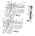
- Nachfolgend werden unter Bezugnahme auf die beigefügten Zeichnungen Ausführungsbeispiele der Erfindung beschrieben. Die Zeichnungen zeigen in:
- Fig. 1
- eine Seitenansicht eines erfindungsgemäßen Wäschebügels,
- Fig. 2
- eine vergrößerte Seitenansicht des Endes der linken Tragbügelhälfte des Wäschebügels aus
Fig. 1 , - Fig. 3
- eine entlang der Schnittlinie III-III in
Fig. 2 geschnittene Darstellung der Klemme, - Fig. 4
- eine Seitenansicht einer alternativen Ausführungsform einer Klemme eines erfindungsgemäßen Wäschebügels.
- Die
Fig. 1 zeigt einen Wäschebügel aus Kunststoff mit doppelt-T-förmigem Querschnitt, einer Stegwand 11, einem Obergurt 12 und einem Untergurt 13. Der Obergurt 12 umschließt auch den Traghaken 2. - Der Tragbügel 1 bildet zwei zu beiden Seiten des Traghakens liegende Tragbügelhälften 1 a, und 1b. An den äußeren Enden der beiden Tragbügelhälften 1a und 1b sind Klemmen 3 angeformt. Die Klemmen bestehen aus einem starr mit dem Tragbügel 1 verbundenen Widerlagerteil 4 und einer federnden Zunge 5, die über ein ¾-ringförmiges Verbindungsteil 6 verbunden ist.
- Um im Innenraum 7 des Verbindungsteils 6 den Freiraum zu einem Spalt zu reduzieren, ist im Innenraum 7 an dem zum Traghaken 2 weisenden ausgesteiften Bereich des Verbindungsteils 6 ein Führungssteg 8 angeordnet. Dem Führungssteg 8 gegenüber liegt ein federnder Finger 9, dessen unteres Ende an das äußere Ende des ringförmigen Verbindungsteils 6 angeformt ist. Zwischen dem federnden Finger 9 und dem Führungssteg 8 verbleibt im oberen Abschnitt des Freiraums zwischen der federnden Zunge 5 und dem Widerlagerteil 4 ein schmaler Spalt 10, der eine Breite von etwa 0,1 mm aufweist. Am oberen Ende ist dieser schmale Spalt 10 durch die obere Innenseite des Verbindungsteils 6 begrenzt.
- Beim Einschieben eines dünnen Stoffbandes, welches das Seitenteil eines String-Tangas bildet, in den Freiraum zwischen Widerlagerteil 4 und federnde Zunge 5 wird am Ende des Einschiebewegs das Bändchen sicher in dem schmalen Spalt 10 gehalten. Der federnde Finger 9 reduziert ein wenig die Andrückkraft, welche in dem schmalen Spalt 10 auf das Stoffbändchen wirkt. Auf diese Weise kann bei einem sicheren Halt eines sehr dünnen Bändchens gleichzeitig eine recht niedrige Kraft gewährleistet werden, die eine Beschädigung des Bändchens ausschließt.
- Die Einzelteile der Klemme und insbesondere der den schmalen Spalt 10 begrenzenden Elemente sind besser in der vergrößerten Ansicht der
Fig. 2 und 3 zu erkennen. In der praktischen Ausführungsform haben die breiten Abschnitte des Wäschebügels, beispielsweise Obergurt 12, Untergurt 13, Verbindungsteil 6 und der die federnde Zunge 5 begrenzende Verstärkungsgurt 14 eine Breite von etwa 5 mm. Die schmalen Teile, nämlich die Stegwand 11, der Führungssteg 8, der federnde Finger 9 und ein Aussteifungssteg 15 der federnden Zunge 5 haben eine Wandstärke von etwa 1,5 mm. - Oberhalb der federnden Zunge 5 ist ein Anschlagsbügel 18 angeformt, der einen Anschlag für die Schwenkbewegung der federnden Zunge 5 bildet.
- Von der äußeren Klemme 3 aus nach innen gelegen sind ferner eine obere Klemme 16 und eine untere Klemme 17 sowie ein Fixierungsbügel 19 angeordnet, welche aus früheren Produkten der Anmelderin bekannt sind. Hierin können andere Bekleidungsstücke wie Unterhemden oder ähnliches befestigt bzw. die befestigten Unterhosen fixiert werden.
- Der in den
Fig. 1 - 3 dargestellte erfindungsgemäße Wäschebügel ist hervorragend geeignet, um Unterhosen mit dünnen bis sehr dünnen seitlichen Bereichen in den Klemmen aufzunehmen. Der Bereich des Zwischenraums zwischen federnder Zunge 5 und Widerlagerteil 4 unterhalb des schmalen Spalts 10 ist ebenfalls recht dünn (unter 1 mm Spaltbreite) und gewellt ausgebildet. Dickere Bünde einer Unterhose können in einem derartig schmalen Spalt beschädigt werden, wenn die Spannkraft zwischen federnder Zunge 5 und Widerlagerteil 4 zu groß ist. -
Fig. 4 zeigt eine alternative Ausführungsform der Klemme 3', in der unterhalb des schmalen Spalts 10 ein großer Freiraum 20 mit einer Breite von etwa 3 mm freigelassen ist, indem der Führungssteg 8' sich nicht in diesen Bereich erstreckt. Hier können neben den Bändchen eines String-Tangas, welche in den oberen Spalt 10 eingeklemmt werden, auch dickere Hosenbünde aufgenommen werden. -
- 1
- Tragbügel
- 1a
- Tragbügelhälfte
- 1b
- Tragbügelhälfte
- 2
- Traghaken
- 3,3'
- äußere Klemme
- 4
- Widerlagerteil
- 5
- federnde Zunge
- 6
- ringförmiges Verbindungsteil
- 7
- Innenraum
- 8,8'
- Führungssteg
- 9
- federnder Finger
- 10
- schmaler Spalt
- 11
- Stegwand
- 12
- Obergurt
- 13
- Untergurt
- 14
- Verstärkungsgurt
- 15
- Aussteifungssteg
- 16
- obere Klemme
- 17
- untere Klemme
- 18
- Anschlagbügel
- 19
- Fixierungsbügel
- 20
- großer Freiraum
- 21
- Führungssteg
Claims (8)
- Wäschebügel, insbesondere zur Aufnahme von Unterhosen, Slips und dergleichen mit- einem Tragbügel (1), der aus zwei Tragbügelhälften (1a und 1b) besteht,- einer in der Mitte des Tragbügels (1) angeordneten Aufhängevorrichtung, die vorzugsweise als Traghaken (2) ausgebildet ist, und- an den äußeren Enden der beiden Tragbügelhälften (1a und 1b) angeformten Klemmen (3,3',3"), die sich jeweils zusammensetzen aus einem Widerlagerteil (4) und einer federnden Zunge (5), die über ein bogenförmiges Verbindungsteil (6) mit dem Widerlagerteil (4) federnd verbunden ist,wobei der Freiraum zwischen Widerlagerteil (4) und federnder Zunge (5) durch einen oberen Anschlag begrenzt ist und daß der an den oberen Anschlag angrenzende Abschnitt des Freiraums zwischen Widerlagerteil (4) und federnder Zunge (5) als schmaler Spalt (10,10') ausgebildet ist,
dadurch gekennzeichnet, daß• das Verbindungsteil (6) ¾-ringförmig ausgebildet ist,• der Spalt (10) durch mindestens einen in den Freiraum im Innenraum des Verbindungsteils (6) hineinragenden inneren Führungssteg (8,8') begrenzt ist und• der Spalt (10) ferner durch einen an der Innenseite des Verbindungsteils (6) angeformten, dem Führungssteg (8,8') gegenüberliegenden, federnden Finger (9) begrenzt ist. - Wäschebügel nach Anspruch 1, dadurch gekennzeichnet, daß der obere Anschlag durch die obere Innenseite des Verbindungsteils (6) gebildet wird.
- Wäschebügel nach Anspruch 1 oder 2, dadurch gekennzeichnet, daß der Spalt (10,10') weniger als 1 mm breit ist.
- Wäschebügel nach einem der vorangehenden Ansprüche, dadurch gekennzeichnet, daß das gebogene Verbindungsteil (6) in einem Abschnitt von einer äußeren Stegwand (11) ausgesteift ist und der Führungssteg (8,8"') im Bereich dieser Stegwand (11) an die Innenseite des Verbindungsteils (6) angeformt ist.
- Wäschebügel nach einem der vorangehenden Ansprüche, dadurch gekennzeichnet, daß der Tragbügel (1) im Querschnitt im wesentlichen doppel-T-förmig ist und eine Stegwand (11) aufweist, welche auch das Widerlagerteil (4) und einen Abschnitt des gebogenen Verbindungsteils (6) aussteift.
- Wäschebügel nach Anspruch 5, dadurch gekennzeichnet, daß das Verbindungsteil (6) um mehr als 50%, vorzugsweise 100%, dicker ist als die Dicke eines Untergurtes (13) oder Obergurtes (12) des Tragbügels (1) und über einen Winkelbereich von mindestens 90° freiliegt und einen Krümmungsdurchmesser von mindestens 6 mm aufweist.
- Wäschebügel nach einem der vorangehenden Ansprüche, dadurch gekennzeichnet, daß der Rand des Führungsstegs (8) wellenförmig verläuft.
- Wäschebügel nach einem der vorangehenden Ansprüche, dadurch gekennzeichnet, daß der nicht ausgesteifte Abschnitt des bogenförmigen Verbindungsteils (6) an seiner Innenseite frei von angeformten Teilen ist.
Applications Claiming Priority (2)
| Application Number | Priority Date | Filing Date | Title |
|---|---|---|---|
| DE20216373U | 2002-10-23 | ||
| DE20216373U DE20216373U1 (de) | 2002-10-23 | 2002-10-23 | Wäschebügel, insbesondere für String-Tanga |
Publications (3)
| Publication Number | Publication Date |
|---|---|
| EP1413233A2 EP1413233A2 (de) | 2004-04-28 |
| EP1413233A3 EP1413233A3 (de) | 2004-12-22 |
| EP1413233B1 true EP1413233B1 (de) | 2009-01-14 |
Family
ID=7976271
Family Applications (1)
| Application Number | Title | Priority Date | Filing Date |
|---|---|---|---|
| EP03024160A Expired - Lifetime EP1413233B1 (de) | 2002-10-23 | 2003-10-20 | Wäschebügel, insbesondere für String-Tanga |
Country Status (3)
| Country | Link |
|---|---|
| EP (1) | EP1413233B1 (de) |
| AT (1) | ATE420579T1 (de) |
| DE (2) | DE20216373U1 (de) |
Families Citing this family (1)
| Publication number | Priority date | Publication date | Assignee | Title |
|---|---|---|---|---|
| DE202011000146U1 (de) | 2011-01-20 | 2011-06-09 | W. Willpütz Kunststoffverarbeitungs GmbH, 50996 | Wäschebügel, zum Beispiel für Büstenhalter |
Family Cites Families (10)
| Publication number | Priority date | Publication date | Assignee | Title |
|---|---|---|---|---|
| US3209966A (en) | 1963-03-04 | 1965-10-05 | Sears Roebuck & Co | Garment hanger |
| US5005742A (en) | 1990-01-16 | 1991-04-09 | Smith James C | Flat garment hanger with retainer slots |
| US5092502A (en) | 1990-09-11 | 1992-03-03 | A & E Products Group | Hanger for thin garments with diversely sized prosections for gripping |
| DE9103803U1 (de) | 1991-03-28 | 1991-06-27 | Dr. Karl Höhn GmbH Papier- und Kartonverarbeitungswerk, 7900 Ulm | Bügel zum Aufhängen von Textilien |
| US5411189A (en) | 1993-09-14 | 1995-05-02 | Spotless Plastics Pty. Ltd. | Garment hanger |
| US5632423A (en) * | 1994-06-30 | 1997-05-27 | Louw; Henry J. | Garment hangers |
| US5573151A (en) | 1994-08-18 | 1996-11-12 | Fildan; G+E,Gra E+Ee Rhard | Garment hanger with waistband and strap clips |
| US6196430B1 (en) * | 1996-05-09 | 2001-03-06 | Spotless Plastics Pty. Ltd. | Garment hanger |
| EP0909138B1 (de) | 1996-07-01 | 2004-08-11 | Spotless Plastics Pty. Ltd. | Kleiderbügel |
| DE29722681U1 (de) * | 1997-12-23 | 1998-04-16 | Willpuetz Kunststoffverarbeitu | Wäschebügel |
-
2002
- 2002-10-23 DE DE20216373U patent/DE20216373U1/de not_active Expired - Lifetime
-
2003
- 2003-10-20 DE DE50311080T patent/DE50311080D1/de not_active Expired - Lifetime
- 2003-10-20 EP EP03024160A patent/EP1413233B1/de not_active Expired - Lifetime
- 2003-10-20 AT AT03024160T patent/ATE420579T1/de active
Also Published As
| Publication number | Publication date |
|---|---|
| EP1413233A3 (de) | 2004-12-22 |
| EP1413233A2 (de) | 2004-04-28 |
| DE20216373U1 (de) | 2002-12-19 |
| ATE420579T1 (de) | 2009-01-15 |
| DE50311080D1 (de) | 2009-03-05 |
Similar Documents
| Publication | Publication Date | Title |
|---|---|---|
| DE69600315T2 (de) | Vorrichtung zum Befestigen horizontalen Konsolen auf einem vertikalen Ständer mit Zahnstangen | |
| DE19882337B4 (de) | Verstellbares flexibles Stirnband für eine Kopfbedeckung | |
| DE3103738A1 (de) | Drehlager fuer den sonnenblendenkoerper von fahrzeug-sonnenblenden | |
| EP1882501A2 (de) | Halter zum Befestigen eines Endes eines Skifells an einem Ende eines Skis | |
| DE3525006A1 (de) | Buegelendstueck fuer einen buegel einer brillenfassung | |
| EP1413233B1 (de) | Wäschebügel, insbesondere für String-Tanga | |
| DE602005001198T2 (de) | Befestigungsvorrichtung für eine rinnen-profilleiste | |
| CH679736A5 (de) | ||
| EP0264086A2 (de) | Halter für einen kartenförmigen Ausweis, Datenträger od.dgl. | |
| DE10304493A1 (de) | Zugfeder für eine elektrische Klemme | |
| DE806666C (de) | Haltevorrichtung fuer Iose Blaetter | |
| DE8218793U1 (de) | Aufreihvorrichtung fuer briefordner oder dgl. | |
| EP0055241A1 (de) | Schliesse | |
| DE10053626B4 (de) | Kleiderbügel | |
| DE3116331C2 (de) | Aufhängevorrichtung für Vorhänge oder dgl. | |
| EP2385161A1 (de) | Fadenfinger für eine Fadenwechselvorrichtung | |
| DE3805603C2 (de) | ||
| EP0398303A2 (de) | Selbsthemmende Klemmvorrichtung | |
| EP0285951A2 (de) | Aufreihvorrichtung für Schriftgutordner oder dergleichen | |
| DE2046510A1 (de) | Haarspange | |
| DE2501030C2 (de) | Aufhänger aus Kunststoff für Vorhänge | |
| EP2478799B1 (de) | Wäschebügel, zum Beispiel für Büstenhalter | |
| DE8916201U1 (de) | Selbsthemmende Klemmvorrichtung | |
| DE10302697B3 (de) | Wickelhaken eines Wickelrahmens | |
| DE7713323U1 (de) | An Gebäudewandungen o.dgl. verlegbarer Kabelführungskanal |
Legal Events
| Date | Code | Title | Description |
|---|---|---|---|
| PUAI | Public reference made under article 153(3) epc to a published international application that has entered the european phase |
Free format text: ORIGINAL CODE: 0009012 |
|
| AK | Designated contracting states |
Kind code of ref document: A2 Designated state(s): AT BE BG CH CY CZ DE DK EE ES FI FR GB GR HU IE IT LI LU MC NL PT RO SE SI SK TR |
|
| AX | Request for extension of the european patent |
Extension state: AL LT LV MK |
|
| PUAL | Search report despatched |
Free format text: ORIGINAL CODE: 0009013 |
|
| AK | Designated contracting states |
Kind code of ref document: A3 Designated state(s): AT BE BG CH CY CZ DE DK EE ES FI FR GB GR HU IE IT LI LU MC NL PT RO SE SI SK TR |
|
| AX | Request for extension of the european patent |
Extension state: AL LT LV MK |
|
| 17P | Request for examination filed |
Effective date: 20050317 |
|
| AKX | Designation fees paid |
Designated state(s): AT BE BG CH CY CZ DE DK EE ES FI FR GB GR HU IE IT LI LU MC NL PT RO SE SI SK TR |
|
| 17Q | First examination report despatched |
Effective date: 20071106 |
|
| GRAP | Despatch of communication of intention to grant a patent |
Free format text: ORIGINAL CODE: EPIDOSNIGR1 |
|
| GRAS | Grant fee paid |
Free format text: ORIGINAL CODE: EPIDOSNIGR3 |
|
| GRAA | (expected) grant |
Free format text: ORIGINAL CODE: 0009210 |
|
| AK | Designated contracting states |
Kind code of ref document: B1 Designated state(s): AT BE BG CH CY CZ DE DK EE ES FI FR GB GR HU IE IT LI LU MC NL PT RO SE SI SK TR |
|
| REG | Reference to a national code |
Ref country code: GB Ref legal event code: FG4D Free format text: NOT ENGLISH |
|
| REG | Reference to a national code |
Ref country code: CH Ref legal event code: EP |
|
| REG | Reference to a national code |
Ref country code: IE Ref legal event code: FG4D Free format text: LANGUAGE OF EP DOCUMENT: GERMAN |
|
| REG | Reference to a national code |
Ref country code: CH Ref legal event code: NV Representative=s name: MICHELI & CIE SA |
|
| REF | Corresponds to: |
Ref document number: 50311080 Country of ref document: DE Date of ref document: 20090305 Kind code of ref document: P |
|
| PG25 | Lapsed in a contracting state [announced via postgrant information from national office to epo] |
Ref country code: SI Free format text: LAPSE BECAUSE OF FAILURE TO SUBMIT A TRANSLATION OF THE DESCRIPTION OR TO PAY THE FEE WITHIN THE PRESCRIBED TIME-LIMIT Effective date: 20090114 Ref country code: ES Free format text: LAPSE BECAUSE OF FAILURE TO SUBMIT A TRANSLATION OF THE DESCRIPTION OR TO PAY THE FEE WITHIN THE PRESCRIBED TIME-LIMIT Effective date: 20090425 Ref country code: FI Free format text: LAPSE BECAUSE OF FAILURE TO SUBMIT A TRANSLATION OF THE DESCRIPTION OR TO PAY THE FEE WITHIN THE PRESCRIBED TIME-LIMIT Effective date: 20090114 |
|
| REG | Reference to a national code |
Ref country code: IE Ref legal event code: FD4D |
|
| PG25 | Lapsed in a contracting state [announced via postgrant information from national office to epo] |
Ref country code: SE Free format text: LAPSE BECAUSE OF FAILURE TO SUBMIT A TRANSLATION OF THE DESCRIPTION OR TO PAY THE FEE WITHIN THE PRESCRIBED TIME-LIMIT Effective date: 20090414 Ref country code: PT Free format text: LAPSE BECAUSE OF FAILURE TO SUBMIT A TRANSLATION OF THE DESCRIPTION OR TO PAY THE FEE WITHIN THE PRESCRIBED TIME-LIMIT Effective date: 20090615 |
|
| PG25 | Lapsed in a contracting state [announced via postgrant information from national office to epo] |
Ref country code: CZ Free format text: LAPSE BECAUSE OF FAILURE TO SUBMIT A TRANSLATION OF THE DESCRIPTION OR TO PAY THE FEE WITHIN THE PRESCRIBED TIME-LIMIT Effective date: 20090114 Ref country code: DK Free format text: LAPSE BECAUSE OF FAILURE TO SUBMIT A TRANSLATION OF THE DESCRIPTION OR TO PAY THE FEE WITHIN THE PRESCRIBED TIME-LIMIT Effective date: 20090114 Ref country code: EE Free format text: LAPSE BECAUSE OF FAILURE TO SUBMIT A TRANSLATION OF THE DESCRIPTION OR TO PAY THE FEE WITHIN THE PRESCRIBED TIME-LIMIT Effective date: 20090114 Ref country code: IE Free format text: LAPSE BECAUSE OF FAILURE TO SUBMIT A TRANSLATION OF THE DESCRIPTION OR TO PAY THE FEE WITHIN THE PRESCRIBED TIME-LIMIT Effective date: 20090114 |
|
| PLBE | No opposition filed within time limit |
Free format text: ORIGINAL CODE: 0009261 |
|
| STAA | Information on the status of an ep patent application or granted ep patent |
Free format text: STATUS: NO OPPOSITION FILED WITHIN TIME LIMIT |
|
| PG25 | Lapsed in a contracting state [announced via postgrant information from national office to epo] |
Ref country code: SK Free format text: LAPSE BECAUSE OF FAILURE TO SUBMIT A TRANSLATION OF THE DESCRIPTION OR TO PAY THE FEE WITHIN THE PRESCRIBED TIME-LIMIT Effective date: 20090114 Ref country code: RO Free format text: LAPSE BECAUSE OF FAILURE TO SUBMIT A TRANSLATION OF THE DESCRIPTION OR TO PAY THE FEE WITHIN THE PRESCRIBED TIME-LIMIT Effective date: 20090114 |
|
| 26N | No opposition filed |
Effective date: 20091015 |
|
| PG25 | Lapsed in a contracting state [announced via postgrant information from national office to epo] |
Ref country code: BG Free format text: LAPSE BECAUSE OF FAILURE TO SUBMIT A TRANSLATION OF THE DESCRIPTION OR TO PAY THE FEE WITHIN THE PRESCRIBED TIME-LIMIT Effective date: 20090414 |
|
| PG25 | Lapsed in a contracting state [announced via postgrant information from national office to epo] |
Ref country code: MC Free format text: LAPSE BECAUSE OF NON-PAYMENT OF DUE FEES Effective date: 20091031 |
|
| PG25 | Lapsed in a contracting state [announced via postgrant information from national office to epo] |
Ref country code: GR Free format text: LAPSE BECAUSE OF FAILURE TO SUBMIT A TRANSLATION OF THE DESCRIPTION OR TO PAY THE FEE WITHIN THE PRESCRIBED TIME-LIMIT Effective date: 20090415 |
|
| PG25 | Lapsed in a contracting state [announced via postgrant information from national office to epo] |
Ref country code: LU Free format text: LAPSE BECAUSE OF NON-PAYMENT OF DUE FEES Effective date: 20091020 |
|
| PG25 | Lapsed in a contracting state [announced via postgrant information from national office to epo] |
Ref country code: HU Free format text: LAPSE BECAUSE OF FAILURE TO SUBMIT A TRANSLATION OF THE DESCRIPTION OR TO PAY THE FEE WITHIN THE PRESCRIBED TIME-LIMIT Effective date: 20090715 |
|
| PG25 | Lapsed in a contracting state [announced via postgrant information from national office to epo] |
Ref country code: TR Free format text: LAPSE BECAUSE OF FAILURE TO SUBMIT A TRANSLATION OF THE DESCRIPTION OR TO PAY THE FEE WITHIN THE PRESCRIBED TIME-LIMIT Effective date: 20090114 |
|
| PG25 | Lapsed in a contracting state [announced via postgrant information from national office to epo] |
Ref country code: CY Free format text: LAPSE BECAUSE OF FAILURE TO SUBMIT A TRANSLATION OF THE DESCRIPTION OR TO PAY THE FEE WITHIN THE PRESCRIBED TIME-LIMIT Effective date: 20090114 |
|
| REG | Reference to a national code |
Ref country code: FR Ref legal event code: PLFP Year of fee payment: 13 |
|
| REG | Reference to a national code |
Ref country code: FR Ref legal event code: PLFP Year of fee payment: 14 |
|
| REG | Reference to a national code |
Ref country code: FR Ref legal event code: PLFP Year of fee payment: 15 |
|
| REG | Reference to a national code |
Ref country code: FR Ref legal event code: PLFP Year of fee payment: 16 |
|
| PGFP | Annual fee paid to national office [announced via postgrant information from national office to epo] |
Ref country code: BE Payment date: 20191022 Year of fee payment: 17 Ref country code: FR Payment date: 20191022 Year of fee payment: 17 Ref country code: IT Payment date: 20191021 Year of fee payment: 17 |
|
| PGFP | Annual fee paid to national office [announced via postgrant information from national office to epo] |
Ref country code: GB Payment date: 20191023 Year of fee payment: 17 |
|
| PGFP | Annual fee paid to national office [announced via postgrant information from national office to epo] |
Ref country code: AT Payment date: 20201016 Year of fee payment: 18 |
|
| GBPC | Gb: european patent ceased through non-payment of renewal fee |
Effective date: 20201020 |
|
| REG | Reference to a national code |
Ref country code: BE Ref legal event code: MM Effective date: 20201031 |
|
| PG25 | Lapsed in a contracting state [announced via postgrant information from national office to epo] |
Ref country code: FR Free format text: LAPSE BECAUSE OF NON-PAYMENT OF DUE FEES Effective date: 20201031 |
|
| PG25 | Lapsed in a contracting state [announced via postgrant information from national office to epo] |
Ref country code: BE Free format text: LAPSE BECAUSE OF NON-PAYMENT OF DUE FEES Effective date: 20201031 Ref country code: GB Free format text: LAPSE BECAUSE OF NON-PAYMENT OF DUE FEES Effective date: 20201020 |
|
| PG25 | Lapsed in a contracting state [announced via postgrant information from national office to epo] |
Ref country code: IT Free format text: LAPSE BECAUSE OF NON-PAYMENT OF DUE FEES Effective date: 20201020 |
|
| REG | Reference to a national code |
Ref country code: AT Ref legal event code: MM01 Ref document number: 420579 Country of ref document: AT Kind code of ref document: T Effective date: 20211020 |
|
| PG25 | Lapsed in a contracting state [announced via postgrant information from national office to epo] |
Ref country code: AT Free format text: LAPSE BECAUSE OF NON-PAYMENT OF DUE FEES Effective date: 20211020 |
|
| PGFP | Annual fee paid to national office [announced via postgrant information from national office to epo] |
Ref country code: NL Payment date: 20221021 Year of fee payment: 20 |
|
| PGFP | Annual fee paid to national office [announced via postgrant information from national office to epo] |
Ref country code: CH Payment date: 20221027 Year of fee payment: 20 |
|
| PGFP | Annual fee paid to national office [announced via postgrant information from national office to epo] |
Ref country code: DE Payment date: 20221227 Year of fee payment: 20 |
|
| REG | Reference to a national code |
Ref country code: DE Ref legal event code: R071 Ref document number: 50311080 Country of ref document: DE |
|
| REG | Reference to a national code |
Ref country code: NL Ref legal event code: MK Effective date: 20231019 |
|
| REG | Reference to a national code |
Ref country code: CH Ref legal event code: PL |