EP1413517A1 - Procédé pour remplir des injecteurs sans aiguille - Google Patents
Procédé pour remplir des injecteurs sans aiguille Download PDFInfo
- Publication number
- EP1413517A1 EP1413517A1 EP04001697A EP04001697A EP1413517A1 EP 1413517 A1 EP1413517 A1 EP 1413517A1 EP 04001697 A EP04001697 A EP 04001697A EP 04001697 A EP04001697 A EP 04001697A EP 1413517 A1 EP1413517 A1 EP 1413517A1
- Authority
- EP
- European Patent Office
- Prior art keywords
- filling
- injector
- filled
- liquid
- filling needle
- Prior art date
- Legal status (The legal status is an assumption and is not a legal conclusion. Google has not performed a legal analysis and makes no representation as to the accuracy of the status listed.)
- Granted
Links
- 238000000034 method Methods 0.000 title claims description 22
- 239000007788 liquid Substances 0.000 claims description 29
- 239000002775 capsule Substances 0.000 claims description 4
- 230000008034 disappearance Effects 0.000 claims description 2
- 239000012530 fluid Substances 0.000 abstract description 3
- 239000011521 glass Substances 0.000 description 11
- 238000007789 sealing Methods 0.000 description 11
- 238000011109 contamination Methods 0.000 description 1
- 230000001419 dependent effect Effects 0.000 description 1
- 238000011161 development Methods 0.000 description 1
- 230000018109 developmental process Effects 0.000 description 1
- 239000000945 filler Substances 0.000 description 1
- 238000005429 filling process Methods 0.000 description 1
- 238000009420 retrofitting Methods 0.000 description 1
Images


Classifications
-
- A—HUMAN NECESSITIES
- A61—MEDICAL OR VETERINARY SCIENCE; HYGIENE
- A61M—DEVICES FOR INTRODUCING MEDIA INTO, OR ONTO, THE BODY; DEVICES FOR TRANSDUCING BODY MEDIA OR FOR TAKING MEDIA FROM THE BODY; DEVICES FOR PRODUCING OR ENDING SLEEP OR STUPOR
- A61M5/00—Devices for bringing media into the body in a subcutaneous, intra-vascular or intramuscular way; Accessories therefor, e.g. filling or cleaning devices, arm-rests
- A61M5/178—Syringes
- A61M5/30—Syringes for injection by jet action, without needle, e.g. for use with replaceable ampoules or carpules
-
- B—PERFORMING OPERATIONS; TRANSPORTING
- B65—CONVEYING; PACKING; STORING; HANDLING THIN OR FILAMENTARY MATERIAL
- B65B—MACHINES, APPARATUS OR DEVICES FOR, OR METHODS OF, PACKAGING ARTICLES OR MATERIALS; UNPACKING
- B65B3/00—Packaging plastic material, semiliquids, liquids or mixed solids and liquids, in individual containers or receptacles, e.g. bags, sacks, boxes, cartons, cans, or jars
- B65B3/003—Filling medical containers such as ampoules, vials, syringes or the like
-
- B—PERFORMING OPERATIONS; TRANSPORTING
- B65—CONVEYING; PACKING; STORING; HANDLING THIN OR FILAMENTARY MATERIAL
- B65B—MACHINES, APPARATUS OR DEVICES FOR, OR METHODS OF, PACKAGING ARTICLES OR MATERIALS; UNPACKING
- B65B3/00—Packaging plastic material, semiliquids, liquids or mixed solids and liquids, in individual containers or receptacles, e.g. bags, sacks, boxes, cartons, cans, or jars
- B65B3/04—Methods of, or means for, filling the material into the containers or receptacles
- B65B3/10—Methods of, or means for, filling the material into the containers or receptacles by application of pressure to material
- B65B3/14—Methods of, or means for, filling the material into the containers or receptacles by application of pressure to material pneumatically
-
- B—PERFORMING OPERATIONS; TRANSPORTING
- B65—CONVEYING; PACKING; STORING; HANDLING THIN OR FILAMENTARY MATERIAL
- B65B—MACHINES, APPARATUS OR DEVICES FOR, OR METHODS OF, PACKAGING ARTICLES OR MATERIALS; UNPACKING
- B65B31/00—Packaging articles or materials under special atmospheric or gaseous conditions; Adding propellants to aerosol containers
- B65B31/04—Evacuating, pressurising or gasifying filled containers or wrappers by means of nozzles through which air or other gas, e.g. an inert gas, is withdrawn or supplied
- B65B31/041—Evacuating, pressurising or gasifying filled containers or wrappers by means of nozzles through which air or other gas, e.g. an inert gas, is withdrawn or supplied the nozzles acting from above on containers or wrappers open at their top
-
- B—PERFORMING OPERATIONS; TRANSPORTING
- B65—CONVEYING; PACKING; STORING; HANDLING THIN OR FILAMENTARY MATERIAL
- B65B—MACHINES, APPARATUS OR DEVICES FOR, OR METHODS OF, PACKAGING ARTICLES OR MATERIALS; UNPACKING
- B65B31/00—Packaging articles or materials under special atmospheric or gaseous conditions; Adding propellants to aerosol containers
- B65B31/04—Evacuating, pressurising or gasifying filled containers or wrappers by means of nozzles through which air or other gas, e.g. an inert gas, is withdrawn or supplied
- B65B31/044—Evacuating, pressurising or gasifying filled containers or wrappers by means of nozzles through which air or other gas, e.g. an inert gas, is withdrawn or supplied the nozzles being combined with a filling device
-
- A—HUMAN NECESSITIES
- A61—MEDICAL OR VETERINARY SCIENCE; HYGIENE
- A61M—DEVICES FOR INTRODUCING MEDIA INTO, OR ONTO, THE BODY; DEVICES FOR TRANSDUCING BODY MEDIA OR FOR TAKING MEDIA FROM THE BODY; DEVICES FOR PRODUCING OR ENDING SLEEP OR STUPOR
- A61M2207/00—Methods of manufacture, assembly or production
-
- A—HUMAN NECESSITIES
- A61—MEDICAL OR VETERINARY SCIENCE; HYGIENE
- A61M—DEVICES FOR INTRODUCING MEDIA INTO, OR ONTO, THE BODY; DEVICES FOR TRANSDUCING BODY MEDIA OR FOR TAKING MEDIA FROM THE BODY; DEVICES FOR PRODUCING OR ENDING SLEEP OR STUPOR
- A61M5/00—Devices for bringing media into the body in a subcutaneous, intra-vascular or intramuscular way; Accessories therefor, e.g. filling or cleaning devices, arm-rests
- A61M5/178—Syringes
- A61M5/1782—Devices aiding filling of syringes in situ
-
- B—PERFORMING OPERATIONS; TRANSPORTING
- B65—CONVEYING; PACKING; STORING; HANDLING THIN OR FILAMENTARY MATERIAL
- B65B—MACHINES, APPARATUS OR DEVICES FOR, OR METHODS OF, PACKAGING ARTICLES OR MATERIALS; UNPACKING
- B65B57/00—Automatic control, checking, warning, or safety devices
- B65B57/10—Automatic control, checking, warning, or safety devices responsive to absence, presence, abnormal feed, or misplacement of articles or materials to be packaged
- B65B57/14—Automatic control, checking, warning, or safety devices responsive to absence, presence, abnormal feed, or misplacement of articles or materials to be packaged and operating to control, or stop, the feed of articles or material to be packaged
- B65B57/145—Automatic control, checking, warning, or safety devices responsive to absence, presence, abnormal feed, or misplacement of articles or materials to be packaged and operating to control, or stop, the feed of articles or material to be packaged for fluent material
Definitions
- Needle-free injectors, capsules or the like are usually filled from the side from which the piston stopper is inserted. However, there are also cases in which the filling should take place from the side of the outlet opening, that is to say through the outlet opening. In the following, only the term injectors is used for this type of container, which is also intended to include the other containers
- the invention has for its object to provide a method and an apparatus for the exact filling of different containers.
- the containers should be filled to the brim and at least approximately free of bubbles.
- the invention proposes a method with the features of claim 1 and a method with the features of claim 5.
- the invention also proposes a device with the features mentioned in claim 13.
- Developments of the invention are the subject of the dependent claims, the wording of which, like the wording of the abstract, is made by reference to the content of the description. Regardless of tolerances of the injector, the piston plug, the stop or the like, the interior of the injector is therefore always completely filled, sometimes even without a metering device having to measure the amount of the liquid to be introduced.
- the method can also be used for injectors of different sizes without retrofitting.
- the injector housing can be filled by means of the so-called suction filling at atmospheric pressure or a slight excess pressure of the liquid.
- the piston stopper is brought to a position corresponding to the desired filling volume before the start of the evacuation. In this position, the plunger stopper is held in place during evacuation and during filling. If a tight-fitting piston is used, no further action is required to hold the piston in this position.
- the position itself can be determined by a stop.
- the disappearance of the vacuum is used to determine the state that the interior of the injector is completely filled.
- the piston plug can be displaced by the pressure of the filled liquid until the filling volume of the injector is reached.
- the filling volume can be predetermined via a metering system, for example suitable pumps.
- the piston is moved by the pressure of the filled-in liquid until a desired position is reached and the reaching of the desired position is used to recognize the filled state.
- the interior of the injector is filled to the brim and without bubbles.
- the target position can be determined, for example, by a fixed stop. In order to be able to carry out the filling quickly enough in this case, it can be provided here that the filling takes place with a significantly greater overpressure by means of the so-called pressure filling.
- the injector to be filled is evacuated beforehand.
- the vacuum bell can be omitted.
- the outlet opening is closed by a stopper.
- the device proposed by the invention can have a holder for the injector to be filled, wherein the holder can preferably have a stop for the piston stopper.
- a vacuum bell is held on the filling needle, in such a way that it can still be moved relative to the filling needle, preferably against the action of a spring. In this way it becomes possible to use the drive for the filling needle to lower the vacuum bell.
- the closure device has a closure rod which axially penetrates the filling needle and which can be moved by a drive.
- a filling needle designed in this way has the advantage that it closes free of drops. Furthermore, such a filling needle can be sterilized in a simple manner.
- the vacuum bell can have a suction opening surrounding the filling needle.
- Evacuation and filling are integrated in a common filling device.
- Sterile filters can be provided at all inlets and outlets of the system that come into contact with the product.
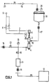
- FIG. 1 shows an overview of a system for suction filling, in which a device according to the invention is arranged.
- the actual device is shown in the middle of FIG. 1. It contains a vacuum bell 1, which is provided with a connection 2 for negative pressure.
- the device also contains a filling device 3, which contains a filling needle 4.
- the filling needle 4 protrudes from the bottom of the vacuum bell 1.
- the injector to be filled which is not shown in FIG. 1, is arranged immediately below the vacuum bell 1 and the filling needle 4.
- the filling needle 4 and the vacuum bell 1 can be lowered and raised again by a first drive 5.
- This drive 5 can be controlled by compressed air, for example.
- a closure device can open and close the filling needle 4.
- pressure lines 7 are provided, which are connected to a compressed air source 9 via control valves 8.
- connection 2 for negative pressure is connected via a valve 10 to a vacuum tank 11, in which the vacuum is maintained by a vacuum pump 12.
- the connection 2 can be ventilated by a further valve 13.
- Sterile filters 14 are present in all lines, since the liquid to be filled is usually medical liquid.
- the pressure prevailing in the line leading to the connection 2 can be measured with the aid of a measuring device 15.
- the filling needle 4 has a connection 16 for the liquid to be filled.
- This connection 16 is connected via a line 17 to a tank 18 in which the liquid to be filled is accommodated.
- a connection to a compressed air source 20 can be established via a control valve 19.
- the pressure prevailing in the tank 18 can also be measured with the aid of a measuring device 20.
- the various valves can be opened and closed via a corresponding control, not shown.
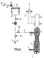
- FIG. 1a shows a schematic representation of the arrangement of a device for pressure filling according to the invention.
- the device contains a filling device 3 with its filling needle 4.
- the filling needle 4 protrudes on the underside from the filling device 3 in the direction of the injector to be filled, which is shown in FIG. 1a.
- the filling device 3 with its filling needle 4 can be lowered and raised again by the first drive 5.
- This drive 5 can be controlled by compressed air, for example, as shown.
- the vacuum bell 1 comes into sealing contact with the sealing sleeve 44, the injector and the space in the sealing sleeve 44 then being able to be evacuated.
- a closure device can open and close the filling needle 4.
- pressure lines 7 are provided, which are connected to a compressed air source 9 via control valves 8.
- the filling needle 4 has a connection 16 for the liquid to be filled.
- This connection 16 is connected via line 17 to the pressure tank 18.
- the liquid to be filled is accommodated in the pressure tank 18.
- a connection to a compressed air source 20 can be established via a control valve 19.
- a sterile filter 14 is preferably arranged between the control valve 19 and the pressure tank 18 on the part of the compressed air supply.
- electrically actuated switching valves 55 are arranged in line 17, for example.
- a further sterile filter 14 can also be arranged in line 17 in the fluid path between tank 18 and filling needle 4. There is also a liquid path which leads from line 17 to a liquid collecting container 56 and via which line 17 can be emptied.
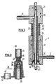
- FIG. 2 shows details of the vacuum bell 1 and the filling needle 4 on a larger scale.
- a hollow cylindrical extension 22 is attached to a component 21, into which the connection 16 for the liquid to be filled opens, on the cylindrical outside of which the vacuum bell 1 is displaceably guided is.
- a spring 25 extends between a shoulder 23 of the component 21 and an end face 24 of the vacuum bell 1 opposite this.
- a tube 26 extends through the hollow cylindrical extension 22 and merges into the filling needle 4 in the region of its free end.
- the filling needle 4 has in the area of its free end, at the bottom in FIG. 2, an opening 27 with a significantly smaller diameter than its outer diameter.
- the tube 26 is connected to the connection 16.
- a closing rod 28 extends through the tube 26 and the filling needle 4 and passes through a side opening in the region of the upper end of the tube 26 through the wall of the feed line for the liquid. There is a seal, not shown.
- the rod is connected to the drive 6 already mentioned and shown in FIG. 1 and can be moved in the direction of the double arrow 29.
- the drive 5 can move the component 21 and thus the filling needle 4 in the direction of the double arrow 30.
- the vacuum bell 1 is also moved at the same time. Only when the vacuum bell 1 strikes a body does it stop, while the filling needle 4 can be moved further.
- connection 2 for negative pressure opens into a cavity 31 surrounding the filling needle, from which air can be sucked in from outside the vacuum bell through a narrow, annular gap 32 from outside the filling needle.
- the vacuum bell 1 has a truncated cone surface 33 surrounding this gap 32, on the end of which facing the gap 32 a seal 34 is arranged.
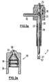
- FIG. 2a shows a schematic representation of the filling needle 4 for filling injectors that do not have a sealing system for sealing the injector-needle tip interface.
- the vacuum bell 1 was not shown.
- the filling needle has a seal 57 on its front edge, which comes into contact with the injector, so that pressure-tight contact with the injector is made possible.
- the connection 16 for the filling device 3 opens into the component 21.
- a hollow cylindrical projection 22 projects from the component 21 in the direction of the injector.
- a tube 26 extends through the hollow cylindrical extension 22 and merges into the filling needle 4 in the region of its free end.
- the filling needle 4 has in the area of its free end, at the bottom in FIG. 2a, an opening 27 with a significantly smaller diameter than its outer diameter.
- a locking rod 28 extends through the tube 26 and the filling needle 4 and passes through a side opening in the region of the upper end of the tube 26 through the wall of the feed line for the liquid ,
- the passage point of the locking rod 28 through the tube 26 is designed to be pressure-tight, so that no leakage of liquid can occur. This seal is not shown in detail.
- the locking rod 28 is connected to the drive 6 shown in FIG. 1 and can be moved in the direction of the double arrow 29.
- the drive 5 can move the component 21 and thus the filling needle 4 in the direction of the double arrow 30, ie in the direction of the injector or away from the injector. During the downward movement of the component 21, the filling needle 4 is moved in the direction of the injector until the seal 57 bears sealingly on the injector.
- the devices shown in Figure 2 and Figure 2a cooperate with the injector 35 shown in Figure 3.
- the injector contains a glass body 36, which is intended to hold the liquid and has a cylindrical interior 37.
- a piston plug 38 is arranged in the interior, which has three circumferential seals and is thereby held in the interior.
- the cylindrical interior 37 merges into a conical space which leads to the outside via a relatively small outlet opening.
- the glass body 36 with the piston plug 38 is inserted in an outer plastic sleeve 39 which forms a holder for a sealing sleeve 40 leading to the outlet opening.
- an outer plastic sleeve 39 which forms a holder for a sealing sleeve 40 leading to the outlet opening.
- the injector 35 is inserted in a sleeve 42 of a receiving nest 43, which is used to transport and hold the injectors 35.
- the receiving nest is designed in the form of a plate and serves to receive several injectors 35.
- the end edge 44 of the sleeve 41 facing away from the glass body 36 is dimensioned such that it is intended and suitable for contact with the underside of the seal 34 of the vacuum bell 1.
- the vacuum bell 1 is lowered onto the sleeve 41 until this end edge 44 abuts the seal 34.
- the sealing sleeve 40 the interior of the glass body 36 is evacuated between its outlet opening and the piston plug 38.
- the filling needle 4 can then be moved into contact with the sealing sleeve 40.
- the glass body 36 is also filled through the sealing sleeve 40.
- FIG. 3a shows a further enlarged detail of the design of an injector, which is particularly suitable for use in a pressure filling.
- the glass body 36 is shown, in which the piston plug 38 is slidably mounted.
- the cylindrical cavity 37 is formed in the glass body, closed by the piston stopper 38.
- the glass body has a conical shape 58, which is particularly advantageous in the case of pressure fillings.
- FIGS. 4 to 9 represent the various stages of the process proposed by the invention.
- Figure 4 shows the starting position of a possible method.
- the injector 35 is held in the receiving nest 43. It is placed on a stop 45 such that the piston plug 38 assumes a certain position that corresponds to the desired set position of the piston plug 38.
- the outlet opening and the sealing sleeve 40 are aligned axially with respect to the filling needle 4.
- the drive 5 By actuating the drive 5, the component 21 with the filling needle 4 and the vacuum bell 1 is lowered. This movement is continued until the seal 34 rests on the end edge 44 so that the spring is biased. Differences in height between the capsules can thus be compensated for. This is shown in Figure 5.
- the connection 2 is now placed under negative pressure, so that the air is sucked out of the interior 37 above the piston plug 38 through the annular gap 32.
- FIG. 7 a bypass is opened in order to reduce any excess pressure that may be present.
- the locking rod 28 is lowered again until it closes the opening 27. This is shown in FIG. 8.
- the space delimited by the sleeve 41 is again ventilated via the vacuum bell 41 so that the vacuum bell 1 can be lifted off the injector 35 again.
- the unit consists of vacuum bell 1 and filling needle 4 raised so that the filled injector 35 can be transported further.
- the method can also be designed so that the piston stopper is pushed further into the interior before the evacuation is started.
- a starting position is shown in FIG. 3.
- the injector 35 is filled to the brim and is at least approximately bubble-free.
Landscapes
- Engineering & Computer Science (AREA)
- Mechanical Engineering (AREA)
- Health & Medical Sciences (AREA)
- Dispersion Chemistry (AREA)
- Chemical & Material Sciences (AREA)
- Biomedical Technology (AREA)
- Heart & Thoracic Surgery (AREA)
- Life Sciences & Earth Sciences (AREA)
- Animal Behavior & Ethology (AREA)
- General Health & Medical Sciences (AREA)
- Public Health (AREA)
- Veterinary Medicine (AREA)
- Hematology (AREA)
- Anesthesiology (AREA)
- Vascular Medicine (AREA)
- Vacuum Packaging (AREA)
- Basic Packing Technique (AREA)
- Infusion, Injection, And Reservoir Apparatuses (AREA)
- Medical Preparation Storing Or Oral Administration Devices (AREA)
Applications Claiming Priority (3)
| Application Number | Priority Date | Filing Date | Title |
|---|---|---|---|
| DE19918721 | 1999-04-24 | ||
| DE19918721A DE19918721A1 (de) | 1999-04-24 | 1999-04-24 | Verfahren und Vorrichtung zum Befüllen von nadelfreien Injektoren |
| EP00927019A EP1171347B1 (fr) | 1999-04-24 | 2000-04-20 | Procede et dispositif de remplissage d'injecteurs sans aiguille |
Related Parent Applications (2)
| Application Number | Title | Priority Date | Filing Date |
|---|---|---|---|
| EP00927019.0 Division | 2000-04-20 | ||
| EP00927019A Division EP1171347B1 (fr) | 1999-04-24 | 2000-04-20 | Procede et dispositif de remplissage d'injecteurs sans aiguille |
Publications (2)
| Publication Number | Publication Date |
|---|---|
| EP1413517A1 true EP1413517A1 (fr) | 2004-04-28 |
| EP1413517B1 EP1413517B1 (fr) | 2007-08-29 |
Family
ID=7905775
Family Applications (2)
| Application Number | Title | Priority Date | Filing Date |
|---|---|---|---|
| EP00927019A Expired - Lifetime EP1171347B1 (fr) | 1999-04-24 | 2000-04-20 | Procede et dispositif de remplissage d'injecteurs sans aiguille |
| EP04001697A Expired - Lifetime EP1413517B1 (fr) | 1999-04-24 | 2000-04-20 | Procédé pour remplir des injecteurs sans aiguille |
Family Applications Before (1)
| Application Number | Title | Priority Date | Filing Date |
|---|---|---|---|
| EP00927019A Expired - Lifetime EP1171347B1 (fr) | 1999-04-24 | 2000-04-20 | Procede et dispositif de remplissage d'injecteurs sans aiguille |
Country Status (6)
| Country | Link |
|---|---|
| US (1) | US6640842B1 (fr) |
| EP (2) | EP1171347B1 (fr) |
| JP (1) | JP2002542127A (fr) |
| AT (2) | ATE371581T1 (fr) |
| DE (3) | DE19918721A1 (fr) |
| WO (1) | WO2000064744A1 (fr) |
Cited By (3)
| Publication number | Priority date | Publication date | Assignee | Title |
|---|---|---|---|---|
| US7956623B2 (en) | 2007-02-16 | 2011-06-07 | Countlab, Inc | Container filling machine |
| US8006468B2 (en) | 2008-04-14 | 2011-08-30 | Countlab Inc. | Container filling machine having vibration trays |
| US8225925B2 (en) | 2008-12-02 | 2012-07-24 | Countlab Inc. | Discrete article spacing apparatus for vibration trays |
Families Citing this family (23)
| Publication number | Priority date | Publication date | Assignee | Title |
|---|---|---|---|---|
| DE19918721A1 (de) | 1999-04-24 | 2000-11-02 | Inova Pac Systeme Gmbh | Verfahren und Vorrichtung zum Befüllen von nadelfreien Injektoren |
| US8459311B2 (en) * | 2002-06-17 | 2013-06-11 | Ronald D. Green | Multi-valve delivery system |
| EP1663787B1 (fr) * | 2003-09-22 | 2010-06-30 | Battelle Memorial Institute | Dispositif de remplissage de recipient |
| DE10346842B4 (de) * | 2003-10-09 | 2015-10-22 | Robert Bosch Gmbh | Vorrichtung zum Füllen und Verschließen von rohrförmigen Behältern, insbesondere in der pharmazeutischen Industrie |
| US20070169434A1 (en) * | 2006-01-26 | 2007-07-26 | Shawn Kinney | Process for aseptic vacuum filling and stoppering of low viscosity liquids in syringes |
| WO2007089295A2 (fr) * | 2006-01-26 | 2007-08-09 | Hyaluron, Inc. | Processus de remplissage sous vide aseptique et de bouchage de liquides à faibles viscosités dans des récipients |
| US20070175538A1 (en) * | 2006-01-30 | 2007-08-02 | Jurgen Rothbauer | System and method for filling containers with liquid under varying pressure conditions |
| US20070267092A1 (en) * | 2006-05-12 | 2007-11-22 | Markus Rink | Vacuum position sensing device |
| CH698602B1 (de) * | 2006-08-09 | 2009-09-15 | Dopag Dosiertechnik Und Pneuma | Vorrichtung und Verfahren zum Befüllen von Spritzenzylindern. |
| US8189967B1 (en) | 2007-09-05 | 2012-05-29 | Wilsons Gun Shop Inc | Fiber optic sight for firearms |
| EP2737952B1 (fr) * | 2009-08-10 | 2016-01-13 | West Pharmaceutical Services, Inc. | Procédé pour remplir des récipients sans flasque |
| US8245889B1 (en) * | 2009-11-03 | 2012-08-21 | Jon Starns | Portable pumpless fuel delivery system |
| US20130042943A1 (en) | 2011-08-18 | 2013-02-21 | Countlab, Inc. | Container filling machine |
| DE102012212527B4 (de) * | 2012-07-18 | 2024-03-28 | Syntegon Technology Gmbh | Verfahren und Vorrichtung zum Konditionieren einer Abfülleinrichtung für flüssige Pharmazeutika vor einer Produktionsphase |
| FR3036389B1 (fr) * | 2015-05-18 | 2019-08-23 | Aptar France Sas | Procede et dispositif de remplissage de reservoir. |
| JP6599208B2 (ja) * | 2015-10-29 | 2019-10-30 | 株式会社吉野工業所 | シリンジ装置への内容物の充填方法 |
| EP3807651A4 (fr) * | 2018-06-14 | 2022-03-16 | Curium US LLC | Station d'évacuation/de remplissage pour la production de récipient de fluide radioactif |
| KR102380848B1 (ko) * | 2020-04-25 | 2022-03-31 | 주식회사 오엘테크 | 황반변성 치료용 임플란트 카트리지 제조 방법 |
| JP2023539254A (ja) * | 2020-08-25 | 2023-09-13 | ヨンヒョン キム | プレフィルド薬液ポンピングアセンブリの製造方法、プレフィルド薬液ポンピングアセンブリ及びプレフィルド薬液注入装置 |
| CN113002828A (zh) * | 2021-03-30 | 2021-06-22 | 陕西煤业化工技术研究院有限责任公司 | 一种纳米吸能材料的灌装系统及其工艺方法 |
| US20240416038A1 (en) * | 2021-07-22 | 2024-12-19 | Dow Silicones Corporation | Apparatus and method for filling syringes |
| CN115957401B (zh) * | 2022-12-02 | 2025-03-18 | 北京快舒尔医疗技术有限公司 | 注射组件和注射系统 |
| CN118439220B (zh) * | 2024-07-08 | 2024-09-17 | 洛阳市奇航化工有限公司 | 一种硅酸钠溶液定量出料装置 |
Citations (6)
| Publication number | Priority date | Publication date | Assignee | Title |
|---|---|---|---|---|
| FR889757A (fr) * | 1943-01-11 | 1944-01-19 | Dispositif de remplissage à l'aiguille et dosage des ampoules de liquide | |
| DE1215541B (de) * | 1961-06-08 | 1966-04-28 | Strunck & Co Maschf H | Vorrichtung zum Fuellen von Ampullen, Flaschen und aehnlichen Behaeltern |
| US4338980A (en) * | 1980-01-14 | 1982-07-13 | Schwebel Paul R | Device for filling medicament injectors |
| DE4320098A1 (de) * | 1993-06-17 | 1994-12-22 | Groninger & Co Gmbh | Verfahren zum Abfüllen |
| WO1997022375A1 (fr) * | 1995-12-16 | 1997-06-26 | Weston Medical Limited | Cartouche de medicament pour injecteur sans aiguille et procede de remplissage associe |
| WO1997036785A1 (fr) * | 1996-04-02 | 1997-10-09 | Weston Medical Limited | Procede pour remplir une capsule avec un medicament et produit resultant |
Family Cites Families (5)
| Publication number | Priority date | Publication date | Assignee | Title |
|---|---|---|---|---|
| US4010747A (en) * | 1974-10-25 | 1977-03-08 | Clark Wesley D | Method of storing an ampoule for a needleless hypodermic injector |
| US4713925A (en) * | 1985-04-01 | 1987-12-22 | Kafkis N H | Method and apparatus for filling a plurality of flexible pipette type vessels |
| FR2668118B1 (fr) * | 1990-10-17 | 1993-12-24 | Valois | Procede de conditionnement de produits liquides a pateux en distributeur sous vide, dispositif pour le mettre en óoeuvre et distributeurs ainsi obtenus. |
| CA2203908A1 (fr) * | 1994-10-28 | 1996-05-09 | Ulrich Speck | Procede pour remplir avec un fluide et obturer des seringues jetables a steriliser |
| DE19918721A1 (de) | 1999-04-24 | 2000-11-02 | Inova Pac Systeme Gmbh | Verfahren und Vorrichtung zum Befüllen von nadelfreien Injektoren |
-
1999
- 1999-04-24 DE DE19918721A patent/DE19918721A1/de not_active Withdrawn
-
2000
- 2000-04-20 AT AT04001697T patent/ATE371581T1/de not_active IP Right Cessation
- 2000-04-20 JP JP2000613708A patent/JP2002542127A/ja active Pending
- 2000-04-20 DE DE50005142T patent/DE50005142D1/de not_active Expired - Lifetime
- 2000-04-20 WO PCT/EP2000/003642 patent/WO2000064744A1/fr not_active Ceased
- 2000-04-20 AT AT00927019T patent/ATE258524T1/de not_active IP Right Cessation
- 2000-04-20 EP EP00927019A patent/EP1171347B1/fr not_active Expired - Lifetime
- 2000-04-20 EP EP04001697A patent/EP1413517B1/fr not_active Expired - Lifetime
- 2000-04-20 US US10/031,262 patent/US6640842B1/en not_active Expired - Fee Related
- 2000-04-20 DE DE50014615T patent/DE50014615D1/de not_active Expired - Lifetime
Patent Citations (6)
| Publication number | Priority date | Publication date | Assignee | Title |
|---|---|---|---|---|
| FR889757A (fr) * | 1943-01-11 | 1944-01-19 | Dispositif de remplissage à l'aiguille et dosage des ampoules de liquide | |
| DE1215541B (de) * | 1961-06-08 | 1966-04-28 | Strunck & Co Maschf H | Vorrichtung zum Fuellen von Ampullen, Flaschen und aehnlichen Behaeltern |
| US4338980A (en) * | 1980-01-14 | 1982-07-13 | Schwebel Paul R | Device for filling medicament injectors |
| DE4320098A1 (de) * | 1993-06-17 | 1994-12-22 | Groninger & Co Gmbh | Verfahren zum Abfüllen |
| WO1997022375A1 (fr) * | 1995-12-16 | 1997-06-26 | Weston Medical Limited | Cartouche de medicament pour injecteur sans aiguille et procede de remplissage associe |
| WO1997036785A1 (fr) * | 1996-04-02 | 1997-10-09 | Weston Medical Limited | Procede pour remplir une capsule avec un medicament et produit resultant |
Cited By (3)
| Publication number | Priority date | Publication date | Assignee | Title |
|---|---|---|---|---|
| US7956623B2 (en) | 2007-02-16 | 2011-06-07 | Countlab, Inc | Container filling machine |
| US8006468B2 (en) | 2008-04-14 | 2011-08-30 | Countlab Inc. | Container filling machine having vibration trays |
| US8225925B2 (en) | 2008-12-02 | 2012-07-24 | Countlab Inc. | Discrete article spacing apparatus for vibration trays |
Also Published As
| Publication number | Publication date |
|---|---|
| EP1413517B1 (fr) | 2007-08-29 |
| US6640842B1 (en) | 2003-11-04 |
| JP2002542127A (ja) | 2002-12-10 |
| ATE371581T1 (de) | 2007-09-15 |
| DE50005142D1 (de) | 2004-03-04 |
| DE50014615D1 (de) | 2007-10-11 |
| ATE258524T1 (de) | 2004-02-15 |
| EP1171347A1 (fr) | 2002-01-16 |
| DE19918721A1 (de) | 2000-11-02 |
| EP1171347B1 (fr) | 2004-01-28 |
| WO2000064744A1 (fr) | 2000-11-02 |
Similar Documents
| Publication | Publication Date | Title |
|---|---|---|
| EP1413517B1 (fr) | Procédé pour remplir des injecteurs sans aiguille | |
| DE60113251T2 (de) | Nadellose spritze mit einem eine isolationsmembran enthaltenden mehrfachkanalinjektor | |
| EP0521460B1 (fr) | Pointe de transfert et prélèvement | |
| DE1902297A1 (de) | Vorrichtung zum Pipettieren mit zusaetzlicher Abgabe einer Reaganzfluessigkeit | |
| DE102009023334A1 (de) | Zur Lagerung von Injektionslösungen geeignete Zylinder-Kolben-Einheit für einen nadelfreien Injektor und Verfahren zum blasenfreien automatischen oder manuellen Befüllen der Zylinder-Kolben-Einheit, auch bei Atmosphärendruck | |
| DE3852499T2 (de) | Vorrichtung zur reparatur von sicherheitsglas. | |
| DE19909995A1 (de) | Verfahren und Vorrichtung zum Befüllen und/oder Evakuieren von Behältern | |
| DE102021109816A1 (de) | Verfahren zum Entleeren von viskosem Material aus einer beidseitig offenen Kartusche sowie hierfür geeignete Entleer-Vorrichtung | |
| DE4324592C1 (de) | Verfahren und Vorrichtung zum Einfüllen einer Flüssigkeit in Gefäße | |
| DE60320543T2 (de) | Verfahren zum Erhalten einer optischen Linse sowie Dichtung und Vorrichtung zum Ausführen des Verfahrens | |
| DE4142567C1 (fr) | ||
| DE19939521A1 (de) | Verfahren zur sauerstoffarmen Abfüllung von Getränken | |
| EP0355456B1 (fr) | Dispositif pour le traitement du sang avec un gaz | |
| DE3307245C2 (de) | Verfahren zum Befüllen eines Behälters mit einem unter Druck stehenden Medium | |
| DE3606977C2 (fr) | ||
| DE69915826T2 (de) | Verfahren, vorrichtung und anlage zum befüllen von behältern | |
| EP3621915A1 (fr) | Dispositif et procédé de remplissage d'un contenant avec un produit de remplissage | |
| DE102008030038A1 (de) | Vorrichtung zur Prüfung der bestimmungsgemäßen Positionierung eines Stopfens in einer einen Hohlkörper aufweisenden Spritze oder Karpule | |
| DE3906361C2 (de) | Vorrichtung zur Prüfung der Dichtigkeit eines flexiblen Kunststoffbehälters | |
| DE1254825B (de) | Injektionsspritze | |
| DE3539167A1 (de) | Einrichtung zur automatischen wasserbefuellung der zellen von elektrobatterien | |
| DE10006474A1 (de) | Verfahren zum Befüllen einer Spritze | |
| CH698602B1 (de) | Vorrichtung und Verfahren zum Befüllen von Spritzenzylindern. | |
| DE3622807A1 (de) | Verfahren zum abfuellen von fluessigkeiten in behaelter | |
| EP3359961B1 (fr) | Procédé pour la séparation de phase d'un mélange liquide et pour la séparation consécutive d'un surnageant liquide et séparateur de phase pour le procédé |
Legal Events
| Date | Code | Title | Description |
|---|---|---|---|
| PUAI | Public reference made under article 153(3) epc to a published international application that has entered the european phase |
Free format text: ORIGINAL CODE: 0009012 |
|
| AC | Divisional application: reference to earlier application |
Ref document number: 1171347 Country of ref document: EP Kind code of ref document: P |
|
| AK | Designated contracting states |
Kind code of ref document: A1 Designated state(s): AT BE CH CY DE DK ES FI FR GB GR IE IT LI LU MC NL PT SE |
|
| RIN1 | Information on inventor provided before grant (corrected) |
Inventor name: DR.GEORG ALFRED KALLMWYER Inventor name: THEO ARNITZ Inventor name: BERND LAUKENMANN Inventor name: JUERGEN ROTHBAUER Inventor name: MICHAEL NIKOLAUS MUELLER |
|
| RIN1 | Information on inventor provided before grant (corrected) |
Inventor name: BERND LAUKENMANN Inventor name: JUERGEN ROTHBAUER Inventor name: MICHAEL NIKOLAUS MUELLER Inventor name: DR.GEORG ALFRED KALLMWYER Inventor name: THEO ARNITZ |
|
| 17P | Request for examination filed |
Effective date: 20040901 |
|
| AKX | Designation fees paid |
Designated state(s): AT BE CH CY DE DK ES FI FR GB GR IE IT LI LU MC NL PT SE |
|
| 17Q | First examination report despatched |
Effective date: 20051007 |
|
| GRAP | Despatch of communication of intention to grant a patent |
Free format text: ORIGINAL CODE: EPIDOSNIGR1 |
|
| GRAS | Grant fee paid |
Free format text: ORIGINAL CODE: EPIDOSNIGR3 |
|
| GRAA | (expected) grant |
Free format text: ORIGINAL CODE: 0009210 |
|
| AC | Divisional application: reference to earlier application |
Ref document number: 1171347 Country of ref document: EP Kind code of ref document: P |
|
| AK | Designated contracting states |
Kind code of ref document: B1 Designated state(s): AT BE CH CY DE DK ES FI FR GB GR IE IT LI LU MC NL PT SE |
|
| REG | Reference to a national code |
Ref country code: GB Ref legal event code: FG4D Free format text: NOT ENGLISH |
|
| REG | Reference to a national code |
Ref country code: CH Ref legal event code: EP |
|
| REG | Reference to a national code |
Ref country code: IE Ref legal event code: FG4D Free format text: LANGUAGE OF EP DOCUMENT: GERMAN |
|
| REF | Corresponds to: |
Ref document number: 50014615 Country of ref document: DE Date of ref document: 20071011 Kind code of ref document: P |
|
| PG25 | Lapsed in a contracting state [announced via postgrant information from national office to epo] |
Ref country code: FI Free format text: LAPSE BECAUSE OF FAILURE TO SUBMIT A TRANSLATION OF THE DESCRIPTION OR TO PAY THE FEE WITHIN THE PRESCRIBED TIME-LIMIT Effective date: 20070829 Ref country code: ES Free format text: LAPSE BECAUSE OF FAILURE TO SUBMIT A TRANSLATION OF THE DESCRIPTION OR TO PAY THE FEE WITHIN THE PRESCRIBED TIME-LIMIT Effective date: 20071210 Ref country code: NL Free format text: LAPSE BECAUSE OF FAILURE TO SUBMIT A TRANSLATION OF THE DESCRIPTION OR TO PAY THE FEE WITHIN THE PRESCRIBED TIME-LIMIT Effective date: 20070829 |
|
| NLV1 | Nl: lapsed or annulled due to failure to fulfill the requirements of art. 29p and 29m of the patents act | ||
| GBV | Gb: ep patent (uk) treated as always having been void in accordance with gb section 77(7)/1977 [no translation filed] |
Effective date: 20070829 |
|
| REG | Reference to a national code |
Ref country code: IE Ref legal event code: FD4D |
|
| EN | Fr: translation not filed | ||
| PG25 | Lapsed in a contracting state [announced via postgrant information from national office to epo] |
Ref country code: DK Free format text: LAPSE BECAUSE OF FAILURE TO SUBMIT A TRANSLATION OF THE DESCRIPTION OR TO PAY THE FEE WITHIN THE PRESCRIBED TIME-LIMIT Effective date: 20070829 Ref country code: GR Free format text: LAPSE BECAUSE OF FAILURE TO SUBMIT A TRANSLATION OF THE DESCRIPTION OR TO PAY THE FEE WITHIN THE PRESCRIBED TIME-LIMIT Effective date: 20071130 |
|
| PG25 | Lapsed in a contracting state [announced via postgrant information from national office to epo] |
Ref country code: IE Free format text: LAPSE BECAUSE OF FAILURE TO SUBMIT A TRANSLATION OF THE DESCRIPTION OR TO PAY THE FEE WITHIN THE PRESCRIBED TIME-LIMIT Effective date: 20070829 Ref country code: GB Free format text: LAPSE BECAUSE OF FAILURE TO SUBMIT A TRANSLATION OF THE DESCRIPTION OR TO PAY THE FEE WITHIN THE PRESCRIBED TIME-LIMIT Effective date: 20070829 Ref country code: PT Free format text: LAPSE BECAUSE OF FAILURE TO SUBMIT A TRANSLATION OF THE DESCRIPTION OR TO PAY THE FEE WITHIN THE PRESCRIBED TIME-LIMIT Effective date: 20080129 |
|
| PG25 | Lapsed in a contracting state [announced via postgrant information from national office to epo] |
Ref country code: SE Free format text: LAPSE BECAUSE OF FAILURE TO SUBMIT A TRANSLATION OF THE DESCRIPTION OR TO PAY THE FEE WITHIN THE PRESCRIBED TIME-LIMIT Effective date: 20071129 |
|
| PLBE | No opposition filed within time limit |
Free format text: ORIGINAL CODE: 0009261 |
|
| STAA | Information on the status of an ep patent application or granted ep patent |
Free format text: STATUS: NO OPPOSITION FILED WITHIN TIME LIMIT |
|
| 26N | No opposition filed |
Effective date: 20080530 |
|
| BERE | Be: lapsed |
Owner name: INOVA PHARMA SYSTEMS G.M.B.H. Effective date: 20080430 |
|
| PG25 | Lapsed in a contracting state [announced via postgrant information from national office to epo] |
Ref country code: MC Free format text: LAPSE BECAUSE OF NON-PAYMENT OF DUE FEES Effective date: 20080430 |
|
| REG | Reference to a national code |
Ref country code: CH Ref legal event code: PL |
|
| PG25 | Lapsed in a contracting state [announced via postgrant information from national office to epo] |
Ref country code: LI Free format text: LAPSE BECAUSE OF NON-PAYMENT OF DUE FEES Effective date: 20080430 Ref country code: CH Free format text: LAPSE BECAUSE OF NON-PAYMENT OF DUE FEES Effective date: 20080430 |
|
| PG25 | Lapsed in a contracting state [announced via postgrant information from national office to epo] |
Ref country code: BE Free format text: LAPSE BECAUSE OF NON-PAYMENT OF DUE FEES Effective date: 20080430 |
|
| PG25 | Lapsed in a contracting state [announced via postgrant information from national office to epo] |
Ref country code: CY Free format text: LAPSE BECAUSE OF FAILURE TO SUBMIT A TRANSLATION OF THE DESCRIPTION OR TO PAY THE FEE WITHIN THE PRESCRIBED TIME-LIMIT Effective date: 20070829 |
|
| PG25 | Lapsed in a contracting state [announced via postgrant information from national office to epo] |
Ref country code: AT Free format text: LAPSE BECAUSE OF NON-PAYMENT OF DUE FEES Effective date: 20080420 |
|
| PG25 | Lapsed in a contracting state [announced via postgrant information from national office to epo] |
Ref country code: LU Free format text: LAPSE BECAUSE OF NON-PAYMENT OF DUE FEES Effective date: 20080420 |
|
| PG25 | Lapsed in a contracting state [announced via postgrant information from national office to epo] |
Ref country code: IT Free format text: LAPSE BECAUSE OF NON-PAYMENT OF DUE FEES Effective date: 20080430 |
|
| PG25 | Lapsed in a contracting state [announced via postgrant information from national office to epo] |
Ref country code: FR Free format text: LAPSE BECAUSE OF FAILURE TO SUBMIT A TRANSLATION OF THE DESCRIPTION OR TO PAY THE FEE WITHIN THE PRESCRIBED TIME-LIMIT Effective date: 20080425 |
|
| PGFP | Annual fee paid to national office [announced via postgrant information from national office to epo] |
Ref country code: DE Payment date: 20140430 Year of fee payment: 15 |
|
| REG | Reference to a national code |
Ref country code: DE Ref legal event code: R119 Ref document number: 50014615 Country of ref document: DE |
|
| PG25 | Lapsed in a contracting state [announced via postgrant information from national office to epo] |
Ref country code: DE Free format text: LAPSE BECAUSE OF NON-PAYMENT OF DUE FEES Effective date: 20151103 |