EP1413691A2 - Wandelement zur Raumgliederung oder Raumgestaltung - Google Patents
Wandelement zur Raumgliederung oder Raumgestaltung Download PDFInfo
- Publication number
- EP1413691A2 EP1413691A2 EP03024280A EP03024280A EP1413691A2 EP 1413691 A2 EP1413691 A2 EP 1413691A2 EP 03024280 A EP03024280 A EP 03024280A EP 03024280 A EP03024280 A EP 03024280A EP 1413691 A2 EP1413691 A2 EP 1413691A2
- Authority
- EP
- European Patent Office
- Prior art keywords
- element according
- wall element
- wall body
- wall
- lighting
- Prior art date
- Legal status (The legal status is an assumption and is not a legal conclusion. Google has not performed a legal analysis and makes no representation as to the accuracy of the status listed.)
- Withdrawn
Links
Images

Classifications
-
- E—FIXED CONSTRUCTIONS
- E04—BUILDING
- E04B—GENERAL BUILDING CONSTRUCTIONS; WALLS, e.g. PARTITIONS; ROOFS; FLOORS; CEILINGS; INSULATION OR OTHER PROTECTION OF BUILDINGS
- E04B2/00—Walls, e.g. partitions, for buildings; Wall construction with regard to insulation; Connections specially adapted to walls
- E04B2/74—Removable non-load-bearing partitions; Partitions with a free upper edge
- E04B2/7407—Removable non-load-bearing partitions; Partitions with a free upper edge assembled using frames with infill panels or coverings only; made-up of panels and a support structure incorporating posts
- E04B2/7416—Removable non-load-bearing partitions; Partitions with a free upper edge assembled using frames with infill panels or coverings only; made-up of panels and a support structure incorporating posts with free upper edge, e.g. for use as office space dividers
- E04B2/7422—Removable non-load-bearing partitions; Partitions with a free upper edge assembled using frames with infill panels or coverings only; made-up of panels and a support structure incorporating posts with free upper edge, e.g. for use as office space dividers with separate framed panels without intermediary support posts
-
- F—MECHANICAL ENGINEERING; LIGHTING; HEATING; WEAPONS; BLASTING
- F21—LIGHTING
- F21V—FUNCTIONAL FEATURES OR DETAILS OF LIGHTING DEVICES OR SYSTEMS THEREOF; STRUCTURAL COMBINATIONS OF LIGHTING DEVICES WITH OTHER ARTICLES, NOT OTHERWISE PROVIDED FOR
- F21V33/00—Structural combinations of lighting devices with other articles, not otherwise provided for
- F21V33/0004—Personal or domestic articles
- F21V33/0012—Furniture
-
- E—FIXED CONSTRUCTIONS
- E04—BUILDING
- E04B—GENERAL BUILDING CONSTRUCTIONS; WALLS, e.g. PARTITIONS; ROOFS; FLOORS; CEILINGS; INSULATION OR OTHER PROTECTION OF BUILDINGS
- E04B2/00—Walls, e.g. partitions, for buildings; Wall construction with regard to insulation; Connections specially adapted to walls
- E04B2/74—Removable non-load-bearing partitions; Partitions with a free upper edge
- E04B2002/7488—Details of wiring
-
- F—MECHANICAL ENGINEERING; LIGHTING; HEATING; WEAPONS; BLASTING
- F21—LIGHTING
- F21Y—INDEXING SCHEME ASSOCIATED WITH SUBCLASSES F21K, F21L, F21S and F21V, RELATING TO THE FORM OR THE KIND OF THE LIGHT SOURCES OR OF THE COLOUR OF THE LIGHT EMITTED
- F21Y2115/00—Light-generating elements of semiconductor light sources
- F21Y2115/10—Light-emitting diodes [LED]
Definitions
- the invention relates to a wall element for dividing or designing a room, in particular a mobile partition, with a preferably sound-absorbing flat wall body and holding means for setting up or hanging up / hanging down the wall body in a building room.
- Wall elements of this type are used primarily in open-plan offices for flexible room division. In addition to a sound-absorbing function, such partitions should also form a screen. Often, however, this also involves additional shading of the workplace in question.
- the object of the invention is to avoid the disadvantages encountered in the prior art and to further improve the utility of a partition.
- the invention is based on the idea of integrating lighting into the wall element. Accordingly it is proposed according to the invention that the wall body delimits at least one internal lighting chamber and that at least one electrical lighting device which is at least partially illuminated during operation is arranged in the lighting chamber. In this way, an additional lighting function can be performed without having to attach ceiling or wall lights. This enables mobile use, whereby the lighting can be changed with the workstation by moving the wall element.
- the integrated installation also fulfills aesthetic and design requirements, since when switched off the illuminants remain hidden from the viewer and in the operating state an appealing backlighting of the wall surface is possible.
- the hollow wall body has an at least partially transparent, in particular transparent outer jacket.
- the light chamber can advantageously be delimited to the outside by a preferably diffusely radiolucent flat material, in particular textile or foil material or glass.
- Indirect lighting if appropriate, can also be achieved in that the wall body has a light outlet that is optically coupled to the illuminant, in particular via a reflector.
- the wall body has a supporting structure, preferably a profile frame composed of profile legs.
- the opening area of the profile frame is advantageously covered by a flat material, in particular acrylic glass plates, preferably with double walls. It is advantageous if the lamps and / or holding means are attached to the supporting frame or profile frame.
- the illuminant is linear or flat, in particular as a fluorescent lamp.
- the illuminant is formed by light-emitting diodes.
- the illuminant is arranged in the region of a flap that can be opened and delimits the lighting chamber. Another improvement provides that the illuminant is slidably arranged on a rail.
- the holding means are formed by brackets attached to a foot edge of the wall body.
- the holding means are formed by anchoring elements which protrude from the wall body and can be connected to a wall or ceiling of the building.
- the power supply can take place without complex installations in that the wall body expediently has a cable duct, preferably leading to its base edge, for the electrical connection of the illuminants via a floor duct on the building side.
- the wall body has a presentation or advertising area backlit by the illuminants.
- the mobile or convertible partition 10 shown in the drawing consists essentially of a flat wall body 12, two foot brackets 14 for tilt-proof installation of the wall body 12 and four light sources 18 arranged in the light chamber 16 formed by the hollow interior of the wall body 12.
- the wall body 12 designed as a panel has a rectangular profile frame 20 and a flat material cover 22 applied to the profile frame on both sides.
- the profile frame 20 is formed from four profile legs 24 that are assembled around a miter.
- a fluorescent lamp forming the illuminant 18 is arranged on each of these profile legs 24.
- flat irons running as foot pieces 14 are attached to the lower profile leg transversely to the frame plane.
- the light chamber 16 in the embodiment shown is formed by the entire interior of the frame between the broadside coverings 22, it is also conceivable that this area is at least partially filled with a structural or insulating material.
- the covering 22 is formed by an at least partially translucent textile or film material.
- the wall body 12 can preferably have an open light outlet on the narrow side, which is optionally optically coupled to the illuminants 18 via a reflector.
- the covering 22 can also serve as a backlit information or advertising area.
- the wall body 12 has a horizontal cross leg 26, on which two L-shaped flaps 28 are articulated in the region of their angular edges 30.
- the flaps 28 shown in an unfolded position are each provided on the inside with a row of light-emitting diodes 18 as illuminants. It is also conceivable that the flaps 28 or a rotationally fixed support bar (not shown) for the light-emitting diodes are arranged displaceably on a rail of the wall body 12.
- a cable routing preferably within the profile frame 20 enables the electrical supply of the lamps 18 via a floor connection.
- switches for the optional actuation of the illuminants 18 can be provided.
Landscapes
- Engineering & Computer Science (AREA)
- Architecture (AREA)
- Physics & Mathematics (AREA)
- Electromagnetism (AREA)
- Civil Engineering (AREA)
- Structural Engineering (AREA)
- Health & Medical Sciences (AREA)
- Public Health (AREA)
- General Engineering & Computer Science (AREA)
- Arrangement Of Elements, Cooling, Sealing, Or The Like Of Lighting Devices (AREA)
- Non-Portable Lighting Devices Or Systems Thereof (AREA)
Abstract
Description
- Die Erfindung betrifft ein Wandelement zur Raumgliederung oder Raumgestaltung, insbesondere mobile Trennwand, mit einem vorzugsweise schalldämmenden flachen Wandkörper und Haltemitteln zum Aufstellen oder Auf/Abhängen des Wandkörpers in einem Gebäuderaum.
- Wandelement dieser Art werden vor allem in Großraumbüros zur flexiblen Raumuntergliederung eingesetzt. Dabei sollen solche Trennwände neben einer schalldämmenden Funktion auch einen Sichtschutz bilden. Häufig ist damit jedoch auch eine zusätzliche Abschattung des betreffenden Arbeitsplatzes verbunden.
- Ausgehend hiervon liegt der Erfindung die Aufgabe zugrunde, die im Stand der Technik aufgetretenen Nachteile zu vermeiden und den Nutzwert einer Trennwand weiter zu verbessern.
- Zur Lösung dieser Aufgabe wird die im Patentanspruch 1 angegebene Merkmalskombination vorgeschlagen. Vorteilhafte Ausgestaltungen und Weiterbildungen der Erfindung ergeben sich aus den abhängigen Ansprüchen.
- Die Erfindung geht von dem Gedanken aus, eine Beleuchtung in das Wandelement zu integrieren. Dementsprechend wird erfindungsgemäß vorgeschlagen, dass der Wandkörper mindestens eine innenliegende Leuchtkammer begrenzt und dass in der Leuchtkammer mindestens ein im Betrieb zumindest bereichsweise nach außen leuchtendes elektrisches Leuchtmittel angeordnet ist. Auf diese Weise kann zusätzlich eine Beleuchtungsfunktion erfüllt werden, ohne dass Decken- oder Wandleuchten angebracht werden müssten. Damit ist ein mobiler Einsatz möglich, wobei die Beleuchtung gleichsam mit dem Arbeitsplatz durch Umsetzen des Wandelement verändert werden kann. Der integrierte Einbau erfüllt auch ästhetische bzw. gestalterische Ansprüche, da im ausgeschalteten Zustand die Leuchtmittel für den Betrachter verborgen bleiben und im Betriebszustand eine ansprechende Hinterleuchtung der Wandfläche möglich ist.
- Eine vorteilhafte Ausführung sieht vor, dass der hohle Wandkörper einen zumindest partiell lichtdurchlässigen, insbesondere transparent ausgebildeten Außenmantel aufweist. Dabei kann die Leuchtkammer vorteilhafterweise durch ein vorzugsweise diffus durchleuchtbares Flachmaterial, insbesondere Textil- oder Folienmaterial oder Glas nach außen begrenzt sein.
- Eine gegebenenfalls indirekte Beleuchtung kann auch dadurch erreicht werden, dass der Wandkörper einen mit dem Leuchtmittel insbesondere über einen Reflektor optisch gekoppelten Lichtauslass aufweist.
- Eine baulich vorteilhafte Ausführung sieht vor, dass der Wandkörper ein Traggerüst, vorzugsweise einen aus Profilschenkeln zusammengesetzten Profilrahmen aufweist. Der Öffnungsbereich des Profilrahmens ist vorteilhafterweise durch ein Flachmaterial, insbesondere Acrylglasplatten vorzugsweise doppelwandig abgedeckt. Dabei ist es günstig, wenn die Leuchtmittel und/oder Haltemittel an dem Traggerüst bzw. Profilrahmen befestigt sind.
- Um die Bautiefe und damit den Raumbedarf zu verringern, ist es vorteilhaft, wenn das Leuchtmittel insbesondere als Leuchtstofflampe linienförmig oder flächig ausgebildet ist.
- Eine weitere vorteilhafte Ausführung sieht vor, dass das Leuchtmittel durch Leuchtdioden gebildet ist.
- Für eine variable Beleuchtung ist es von Vorteil, wenn das Leuchtmittel im Bereich einer aufklappbaren, die Leuchtkammer begrenzenden Klappe angeordnet ist. Eine weitere Verbesserung sieht vor, dass das Leuchtmittel an einer Schiene verschiebbar angeordnet ist.
- Eine Anpassung an wechselnde Beleuchtungsanforderungen ist auch dadurch möglich, dass mehrere Leuchtmittel über zugeordnete Schalterelemente wahlweise betätigbar sind.
- Zur kippsicheren Aufstellung ist es von Vorteil, wenn die Haltemittel durch an einer Fußkante des Wandkörpers befestigte Ausleger gebildet sind. Zum wandseitigen Aufhängen oder deckenseitigen Abhängen ist es vorteilhaft, wenn die Haltemittel durch an dem Wandkörper abstehende und mit einer Wand oder Decke des Gebäudes verbindbare Verankerungselemente gebildet sind.
- Die Stromversorgung kann ohne aufwendige Installationen dadurch erfolgen, dass der Wandkörper eine vorzugsweise zu seiner Fußkante führende Kabelführung für den elektrischen Anschluss der Leuchtmittel zweckmäßig über einen gebäudeseitigen Bodenkanal aufweist.
- Ein Zusatznutzen kann dadurch erreicht werden, dass der Wandkörper eine durch die Leuchtmittel hinterleuchtete Präsentations- oder Werbefläche aufweist.
- Im folgenden wird die Erfindung anhand der in der Zeichnung in schematischer Weise dargestellten Ausführungsbeispiele näher erläutert. Es zeigen
- Fig. 1
- eine mobile Trennwand mit einem hohlen Wandkörper und darin angeordneten Leuchtmitteln in einer teilweise aufgebrochenen perspektivischen Darstellung;
- Fig. 2
- eine Schmalseitenansicht der Trennwand nach Fig. 1;
- Fig. 3
- einen Tragrahmen der Trennwand mit daran angebrachten Leuchtmitteln in einer Breitseitenansicht; und
- Fig. 4
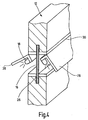
- eine weitere Ausführungsform einer Trennwand mit aufklappbarer Lichtleiste in LED-Technik in einer ausschnittsweisen perspektivischen Ansicht.
- Die in der Zeichnung dargestellte mobile bzw. umsetzbare Trennwand 10 besteht im wesentlichen aus einem flachen Wandkörper 12, zwei Fußauslegern 14 zum kippfesten Aufstellen des Wandkörpers 12 und vier in der durch den hohlen Innenraum des Wandkörpers 12 gebildeten Leuchtkammer 16 angeordneten Leuchtmitteln 18.
Der als Paneel ausgebildete Wandkörper 12 weist einen rechteckförmigen Profilrahmen 20 sowie eine beidseitig auf den Profilrahmen aufgebrachte Flachmaterialabdeckung 22 auf. Wie am besten aus Fig. 3 ersichtlich, ist der Profilrahmen 20 aus vier umlaufend auf Gehrung zusammengesetzten Profilschenkeln 24 gebildet. An diesen Profilschenkeln 24 ist jeweils eine das Leuchtmittel 18 bildende Leuchtstofflampe angeordnet. Zusätzlich sind an dem unteren Profilschenkel quer zur Rahmenebene verlaufende Flacheisen als Fußstücke 14 angebracht. - Während die Leuchtkammer 16 in der gezeigten Ausführung durch den gesamten Rahmeninnenraum zwischen den breitseitigen Bespannungen 22 gebildet wird, ist es auch denkbar, dass dieser Bereich zumindest teilweise mit einem Struktur- oder Dämmmaterial ausgefüllt ist.
- Um eine diffuse Beleuchtung zu ermöglichen, ist es vorgesehen, dass die Bespannung 22 durch ein zumindest partiell lichtdurchlässiges Textil- oder Folienmaterial gebildet ist. Alternativ oder ergänzend kann der Wandkörper 12 vorzugsweise schmalseitig einen offenen Lichtauslass aufweisen, welcher gegebenenfalls über einen Reflektor mit den Leuchtmitteln 18 optisch gekoppelt ist. Die Bespannung 22 kann dabei zugleich als hinterleuchtete Informations- oder Werbefläche dienen.
- Bei der in Fig. 4 gezeigten Ausführungsform weist der Wandkörper 12 einen horizontalen Querschenkel 26 auf, an welchem zwei L-förmige Klappen 28 im Bereich ihrer Winkelkanten 30 angelenkt sind. Die in einer aufgeklappten Stellung gezeigten Klappen 28 sind innenseitig jeweils mit einer Reihe von Leuchtdioden 18 als Leuchtmittel versehen. Denkbar ist es auch, dass die Klappen 28 oder eine nicht gezeigte drehfeste Tragleiste für die Leuchtdioden an einer Schiene des Wandkörpers 12 verschiebbar angeordnet sind.
- Eine nicht eigens dargestellte Kabelführung vorzugsweise innerhalb des Profilrahmens 20 ermöglicht die elektrische Versorgung der Leuchtmittel 18 über einen Bodenanschluss. Zusätzlich können Schalter zur wahlweisen Betätigung der Leuchtmittel 18 vorgesehen sein.
Claims (16)
- Wandelement zur Raumgliederung oder Raumgestaltung, insbesondere mobile Trennwand, mit einem vorzugsweise schalldämmenden flachen Wandkörper (12) und Haltemitteln (14) zum Aufstellen oder Auf/Abhängen des Wandkörpers (12) in einem Gebäuderaum, dadurch gekennzeichnet, dass der Wandkörper (12) mindestens eine innenliegende Leuchtkammer (16) begrenzt und dass in der Leuchtkammer (16) mindestens ein im Betrieb zumindest bereichsweise nach außen leuchtendes elektrisches Leuchtmittel (18) angeordnet ist.
- Wandelement nach Anspruch 1, dadurch gekennzeichnet, dass der hohle Wandkörper (12) einen zumindest partiell lichtdurchlässigen, insbesondere transparent ausgebildeten Außenmantel (22) aufweist.
- Wandelement nach Anspruch 1 oder 2, dadurch gekennzeichnet, dass die Leuchtkammer (16) durch ein vorzugsweise diffus durchleuchtbares Flachmaterial, insbesondere Textil- oder Folienmaterial oder Glas nach außen begrenzt ist.
- Wandelement nach einem der Ansprüche 1 bis 3, dadurch gekennzeichnet, dass der Wandkörper (12) einen mit dem Leuchtmittel (18) insbesondere über einen Reflektor optisch gekoppelten Lichtauslass aufweist.
- Wandelement nach einem der Ansprüche 1 bis 4, dadurch gekennzeichnet, dass der Wandkörper (12) ein Traggerüst (20) aufweist.
- Wandelement nach einem der Ansprüche 1 bis 5, dadurch gekennzeichnet, dass der Wandkörper (12) einen aus Profilschenkeln zusammengesetzten Profilrahmen (20) aufweist, und dass der Öffnungsbereich des Profilrahmens durch ein Flachmaterial (22), insbesondere Acrylglasplatten vorzugsweise doppelwandig abgedeckt ist.
- Wandelement nach Anspruch 5 oder 6, dadurch gekennzeichnet, dass das Leuchtmittel (18) und/oder Haltemittel (14) an dem Traggerüst (20) befestigt ist.
- Wandelement nach einem der Ansprüche 1 bis 7, dadurch gekennzeichnet, dass das Leuchtmittel (18) insbesondere als Leuchtstofflampe linienförmig oder flächig ausgebildet ist.
- Wandelement nach einem der Ansprüche 1 bis 7, dadurch gekennzeichnet, dass das Leuchtmittel (18) durch Leuchtdioden gebildet ist.
- Wandelement nach einem der Ansprüche 1 bis 9, dadurch gekennzeichnet, dass das Leuchtmittel (18) im Bereich einer aufklappbaren, die Leuchtkammer (16) begrenzenden Klappe (28) angeordnet ist.
- Wandelement nach einem der Ansprüche 1 bis 10, dadurch gekennzeichnet, dass das Leuchtmittel (18) an einer Schiene (26) verschiebbar angeordnet ist.
- Wandelement nach einem der Ansprüche 1 bis 11, dadurch gekennzeichnet, dass mehrere Leuchtmittel (18) über zugeordnete Schalterelemente wahlweise betätigbar sind.
- Wandelement nach einem der Ansprüche 1 bis 12, dadurch gekennzeichnet, dass die Haltemittel durch an einer Fußkante des Wandkörpers (12) befestigte Ausleger (14) gebildet sind.
- Wandelement nach einem der Ansprüche 1 bis 12, dadurch gekennzeichnet, dass die Haltemittel (14) durch an dem Wandkörper (12) abstehende und mit einer Wand oder Decke des Gebäudes verbindbare Verankerungselemente gebildet sind.
- Wandelement nach einem der Ansprüche 1 bis 14, dadurch gekennzeichnet, dass der Wandkörper (12) eine vorzugsweise zu seiner Fußkante führende Kabelführung für den elektrischen Anschluss der Leuchtmittel (18) aufweist.
- Wandelement nach einem der Ansprüche 1 bis 15, dadurch gekennzeichnet, dass der Wandkörper (12) eine durch die Leuchtmittel (18) hinterleuchtete Präsentationsfläche aufweist.
Applications Claiming Priority (2)
| Application Number | Priority Date | Filing Date | Title |
|---|---|---|---|
| DE10249807A DE10249807A1 (de) | 2002-10-24 | 2002-10-24 | Wandelement zur Raumgliederung oder Raumgestaltung |
| DE10249807 | 2002-10-24 |
Publications (2)
| Publication Number | Publication Date |
|---|---|
| EP1413691A2 true EP1413691A2 (de) | 2004-04-28 |
| EP1413691A3 EP1413691A3 (de) | 2004-12-22 |
Family
ID=32049613
Family Applications (1)
| Application Number | Title | Priority Date | Filing Date |
|---|---|---|---|
| EP03024280A Withdrawn EP1413691A3 (de) | 2002-10-24 | 2003-10-23 | Wandelement zur Raumgliederung oder Raumgestaltung |
Country Status (2)
| Country | Link |
|---|---|
| EP (1) | EP1413691A3 (de) |
| DE (1) | DE10249807A1 (de) |
Cited By (2)
| Publication number | Priority date | Publication date | Assignee | Title |
|---|---|---|---|---|
| AT509687B1 (de) * | 2010-04-09 | 2012-04-15 | Hierzer Andreas | Trennwand mit integrierter beleuchtung |
| WO2015000874A1 (en) * | 2013-07-02 | 2015-01-08 | Koninklijke Philips N.V. | Sound attenuating panel |
Families Citing this family (2)
| Publication number | Priority date | Publication date | Assignee | Title |
|---|---|---|---|---|
| DE202006005039U1 (de) | 2006-03-22 | 2006-07-06 | Octanorm-Vertriebs-GmbH für Bauelemente | Profil für eine Leuchtwand und Leuchtwandprofilsystem |
| DE202008000413U1 (de) * | 2008-01-08 | 2009-05-20 | Munichfashion.Company Gmbh | Leuchtwand Weiß |
Family Cites Families (2)
| Publication number | Priority date | Publication date | Assignee | Title |
|---|---|---|---|---|
| US4876835A (en) * | 1984-09-10 | 1989-10-31 | Herman Miller, Inc. | Work space management system |
| US6311441B1 (en) * | 2000-03-13 | 2001-11-06 | The Artglo Company | Panel-based modular wall system |
-
2002
- 2002-10-24 DE DE10249807A patent/DE10249807A1/de not_active Withdrawn
-
2003
- 2003-10-23 EP EP03024280A patent/EP1413691A3/de not_active Withdrawn
Cited By (4)
| Publication number | Priority date | Publication date | Assignee | Title |
|---|---|---|---|---|
| AT509687B1 (de) * | 2010-04-09 | 2012-04-15 | Hierzer Andreas | Trennwand mit integrierter beleuchtung |
| EP2375151A3 (de) * | 2010-04-09 | 2013-12-11 | Andreas Hierzer | Trennwand mit integrierter Beleuchtung |
| WO2015000874A1 (en) * | 2013-07-02 | 2015-01-08 | Koninklijke Philips N.V. | Sound attenuating panel |
| CN105340002A (zh) * | 2013-07-02 | 2016-02-17 | 皇家飞利浦有限公司 | 声音衰减面板 |
Also Published As
| Publication number | Publication date |
|---|---|
| DE10249807A1 (de) | 2004-05-13 |
| EP1413691A3 (de) | 2004-12-22 |
Similar Documents
| Publication | Publication Date | Title |
|---|---|---|
| EP2375151B1 (de) | Trennwand mit integrierter beleuchtung | |
| WO2005066540A1 (de) | Beleuchtungseinrichtung | |
| EP1413691A2 (de) | Wandelement zur Raumgliederung oder Raumgestaltung | |
| EP3804563B1 (de) | Spiegelschrank, insbesondere für ein badezimmer | |
| EP2886950A1 (de) | Leuchte | |
| DE202004013324U1 (de) | Lichtquelle zur Innenraumbeleuchtung | |
| DE202005005616U1 (de) | Trennwandelement | |
| EP1832808B1 (de) | Leuchtenanordnung sowie daraus hergestellter Sichtschutz, Raumteiler und Glasscheibenelement | |
| AT509646B1 (de) | Zwischendeckenlichtsystem | |
| EP3524880A1 (de) | Pfettenprofil, terrassenüberdachung | |
| DE20104346U1 (de) | Leuchte | |
| DE10036312B4 (de) | Heizgerät, insbesondere Kaminofen | |
| AT413438B (de) | Leuchte | |
| EP1045196A2 (de) | Beleuchtungseinrichtung mit einer Tragbasis | |
| DE4315640C1 (de) | Dachleuchte auf einem Telefonhäuschen oder einer Telefonhaube | |
| DE202007013177U1 (de) | Leuchte | |
| EP1918635B1 (de) | Stimmungsleuchte | |
| DE102006001976A1 (de) | Leuchte umfassend eine Scheibe | |
| DE19522055C1 (de) | Beleuchtungsanlage für eine eine Bühnenfläche aufweisende Bühne | |
| DE1764535C3 (de) | Leuchte | |
| DE9304479U1 (de) | Leuchte | |
| DE102011077742B4 (de) | Leuchte mit einem Leuchtelement | |
| EP1876386A2 (de) | Vorrichtung zur Beleuchtung | |
| DE202004003955U1 (de) | Stehleuchte | |
| DE29822249U1 (de) | Beleuchtungseinrichtung für einen Schirm |
Legal Events
| Date | Code | Title | Description |
|---|---|---|---|
| PUAI | Public reference made under article 153(3) epc to a published international application that has entered the european phase |
Free format text: ORIGINAL CODE: 0009012 |
|
| AK | Designated contracting states |
Kind code of ref document: A2 Designated state(s): AT BE BG CH CY CZ DE DK EE ES FI FR GB GR HU IE IT LI LU MC NL PT RO SE SI SK TR |
|
| AX | Request for extension of the european patent |
Extension state: AL LT LV MK |
|
| PUAL | Search report despatched |
Free format text: ORIGINAL CODE: 0009013 |
|
| AK | Designated contracting states |
Kind code of ref document: A3 Designated state(s): AT BE BG CH CY CZ DE DK EE ES FI FR GB GR HU IE IT LI LU MC NL PT RO SE SI SK TR |
|
| AX | Request for extension of the european patent |
Extension state: AL LT LV MK |
|
| AKX | Designation fees paid | ||
| REG | Reference to a national code |
Ref country code: DE Ref legal event code: 8566 |
|
| STAA | Information on the status of an ep patent application or granted ep patent |
Free format text: STATUS: THE APPLICATION IS DEEMED TO BE WITHDRAWN |
|
| 18D | Application deemed to be withdrawn |
Effective date: 20050623 |