EP1413767A2 - Assemblage de roue de compresseur - Google Patents
Assemblage de roue de compresseur Download PDFInfo
- Publication number
- EP1413767A2 EP1413767A2 EP03256589A EP03256589A EP1413767A2 EP 1413767 A2 EP1413767 A2 EP 1413767A2 EP 03256589 A EP03256589 A EP 03256589A EP 03256589 A EP03256589 A EP 03256589A EP 1413767 A2 EP1413767 A2 EP 1413767A2
- Authority
- EP
- European Patent Office
- Prior art keywords
- compressor wheel
- shaft
- bore
- wheel
- compressor
- Prior art date
- Legal status (The legal status is an assumption and is not a legal conclusion. Google has not performed a legal analysis and makes no representation as to the accuracy of the status listed.)
- Withdrawn
Links
Images

Classifications
-
- F—MECHANICAL ENGINEERING; LIGHTING; HEATING; WEAPONS; BLASTING
- F02—COMBUSTION ENGINES; HOT-GAS OR COMBUSTION-PRODUCT ENGINE PLANTS
- F02B—INTERNAL-COMBUSTION PISTON ENGINES; COMBUSTION ENGINES IN GENERAL
- F02B39/00—Component parts, details, or accessories relating to, driven charging or scavenging pumps, not provided for in groups F02B33/00 - F02B37/00
-
- F—MECHANICAL ENGINEERING; LIGHTING; HEATING; WEAPONS; BLASTING
- F04—POSITIVE - DISPLACEMENT MACHINES FOR LIQUIDS; PUMPS FOR LIQUIDS OR ELASTIC FLUIDS
- F04D—NON-POSITIVE-DISPLACEMENT PUMPS
- F04D29/00—Details, component parts, or accessories
- F04D29/26—Rotors specially for elastic fluids
- F04D29/266—Rotors specially for elastic fluids mounting compressor rotors on shafts
Definitions
- This invention relates to the assembly of a compressor wheel to a rotating shaft.
- the invention relates to the compressor wheel assembly of a turbocharger.
- Turbochargers are well known devices for supplying air to the intake of an internal combustion engine at pressures above atmospheric (boost pressures).
- a conventional turbocharger essentially comprises an exhaust gas driven turbine wheel mounted on a rotatable shaft within a turbine housing. Rotation of the turbine wheel rotates a compressor wheel mounted on the other end of the shaft within a compressor housing. The compressor wheel delivers compressed air to the intake manifold of the engine, thereby increasing engine power.
- the shaft is supported on journal and thrust bearings located within a central bearing housing connected between the turbine and compressor wheel housings.
- a conventional compressor wheel comprises an array of blades extending from a central hub provided with a bore for receiving one end of the turbocharger shaft.
- the compressor wheel is secured to the shaft by a nut which threads onto the end of the shaft where it extends through the wheel bore, and bears against the nose end of the wheel to clamp the wheel against a shaft shoulder (or other radially extending abutment that rotates with the shaft).
- a compressor wheel assembly comprising a compressor wheel mounted to a rotating shaft, the shaft extending through a bore provided along the rotational axis of the wheel, wherein the bore has an inner diameter greater than the outer diameter of the portion of the shaft which passes through the compressor wheel, and a cylindrical sleeve is located concentrically around the shaft between the inner surface of the bore and the outer surface of the shaft to thereby support the shaft co-axially within the bore.
- the present invention enables the shaft bore to be machined with a diameter suitable for accurate mass production, the bore diameter then effectively being reduced to suite the shaft diameter by provision of said sleeve. The manufacturing difficulties of the prior art are therefore avoided.
- the sleeve may be pre-fitted to the compressor wheel.
- the present invention also provides a compressor wheel for a turbocharger, which in use is mounted to one end of a turbocharger shaft, wherein the compressor wheel defines an internal axial through bore of a relatively large diameter, and is provided with a cylindrical sleeve of a relatively small inner diameter, selected to correspond to the diameter of the shaft, located co-axially within said bore.
- FIG. 1 illustrates the basic components of a conventional centripetal type turbocharger.
- the turbocharger comprises a turbine 1 joined to a compressor 2 via a central bearing housing 3.
- the turbine 1 comprises a turbine housing 4 which houses a turbine wheel 5.
- the compressor 2 comprises a compressor housing 6 which houses a compressor wheel 7.
- the turbine wheel 5 and compressor wheel 7 are mounted on opposite ends of a common shaft 8 which is supported on bearing assemblies 9 within the bearing housing 3.
- the turbine housing 4 is provided with an exhaust gas inlet 10 and an exhaust gas outlet 11.
- the inlet 10 directs incoming exhaust gas to an annular inlet chamber 12 surrounding the turbine wheel 5.
- the exhaust gas flows through the turbine and into the outlet 11 via a circular outlet opening which is co-axial with the turbine wheel 5.
- Rotation of the turbine wheel 5 rotates the compressor wheel 7 which draws in air through axial inlet 13 and delivers compressed air to the engine intake via an annular outlet volute 14.
- the compressor wheel comprises a plurality of blades 15 extending from a central hub 16 which is provided with a through bore to receive one end of the shaft 8.
- the shaft 8 extends slightly from the nose of the compressor wheel 7 and is threaded to receive a nut 17 which bears against the compressor wheel nose to clamp the compressor wheel 7 against a thrust bearing and oil seal assembly 18.
- Details of the thrust bearing/oil seal assembly may vary and are not important to understanding of the compressor wheel mounting arrangement. Essentially, the compressor wheel 7 is prevented from slipping on the shaft 8 by the clamping force applied by the nut 17.
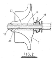
- Figure 2 illustrates a compressor wheel assembly in accordance with the present invention. Details of the shaft 8, thrust bearing and seal assembly 18, and clamp nut 17 may be entirely conventional, as for instance illustrated in Figure 1.
- the compressor wheel bore 21 has a relatively large diameter (i.e. larger than the diameter of the shaft 8) and in particular is of a size that can be easily machined and mass produced to the required accuracy.
- the diameter of the bore 21 is then effectively reduced to the diameter of the shaft 8 by introduction of a cylindrical sleeve 22 in to the bore 21.
- the sleeve 22 has an outer diameter corresponding to the inner diameter of the bore 21, and an inner diameter corresponding to the outer diameter of the shaft 8. The shaft 8 is therefore accurately located and maintained along the axis of the bore 21.
- the sleeve 21 is provided slightly shorter than the length of the bore 20 to ensure that the clamping force is transferred through the compressor wheel and not through the sleeve.
- the sleeve 21 Since the sleeve 21 is not subjected to the same stresses as the compressor wheel, it may be manufactured from a material which is much easier to work than the material of the compressor wheel.
- the relatively small diameter bore required to mount a compressor wheel on to a small diameter shaft can be provided with a high degree of accuracy and manufacturing ease. Since the sleeve 21 fits within the bore 20 in the same manner as would a larger diameter shaft, wheel balancing issues are essentially unchanged. In addition, with the present invention it is not necessary to modify other components of the compressor wheel assembly, such as the wheel clamping arrangement.
Landscapes
- Engineering & Computer Science (AREA)
- Mechanical Engineering (AREA)
- General Engineering & Computer Science (AREA)
- Chemical & Material Sciences (AREA)
- Combustion & Propulsion (AREA)
- Structures Of Non-Positive Displacement Pumps (AREA)
- Supercharger (AREA)
- Compressor (AREA)
- Turbine Rotor Nozzle Sealing (AREA)
Applications Claiming Priority (2)
| Application Number | Priority Date | Filing Date | Title |
|---|---|---|---|
| GB0224723 | 2002-10-24 | ||
| GBGB0224723.7A GB0224723D0 (en) | 2002-10-24 | 2002-10-24 | Compressor wheel assembly |
Publications (2)
| Publication Number | Publication Date |
|---|---|
| EP1413767A2 true EP1413767A2 (fr) | 2004-04-28 |
| EP1413767A3 EP1413767A3 (fr) | 2005-04-13 |
Family
ID=9946475
Family Applications (1)
| Application Number | Title | Priority Date | Filing Date |
|---|---|---|---|
| EP03256589A Withdrawn EP1413767A3 (fr) | 2002-10-24 | 2003-10-20 | Assemblage de roue de compresseur |
Country Status (6)
| Country | Link |
|---|---|
| US (1) | US20040126231A1 (fr) |
| EP (1) | EP1413767A3 (fr) |
| JP (1) | JP2004144094A (fr) |
| KR (1) | KR20040036655A (fr) |
| CN (1) | CN1508445A (fr) |
| GB (1) | GB0224723D0 (fr) |
Cited By (2)
| Publication number | Priority date | Publication date | Assignee | Title |
|---|---|---|---|---|
| CN102639841A (zh) * | 2009-12-22 | 2012-08-15 | 博格华纳公司 | 排气涡轮增压器的轴组件 |
| WO2015175214A1 (fr) | 2014-05-12 | 2015-11-19 | Borgwarner Inc. | Roue de compresseur comportant un manchon en titane |
Families Citing this family (17)
| Publication number | Priority date | Publication date | Assignee | Title |
|---|---|---|---|---|
| GB0224727D0 (en) * | 2002-10-24 | 2002-12-04 | Holset Engineering Co | Compressor wheel assembly |
| GB0224726D0 (en) * | 2002-10-24 | 2002-12-04 | Holset Engineering Co | Compressor wheel assembly |
| GB0224721D0 (en) * | 2002-10-24 | 2002-12-04 | Holset Engineering Co | Compressor wheel assembly |
| JP4053563B2 (ja) * | 2005-12-01 | 2008-02-27 | ファナック株式会社 | 流体機械 |
| DE602006020239D1 (de) | 2006-01-24 | 2011-04-07 | Ihi Corp | Motorbetriebene Aufladung |
| EP1813782B1 (fr) | 2006-01-26 | 2009-08-05 | IHI Corporation | Turbo-Surpresseur |
| WO2007108234A1 (fr) * | 2006-03-23 | 2007-09-27 | Ihi Corporation | Arbre à haute vitesse de rotation pour compresseur |
| JP4753033B2 (ja) | 2006-06-02 | 2011-08-17 | 株式会社Ihi | 電動過給機 |
| CN101506489B (zh) | 2006-08-18 | 2011-11-16 | 株式会社Ihi | 电动增压器 |
| JP4826417B2 (ja) * | 2006-09-29 | 2011-11-30 | 株式会社ジェイテクト | 過給器 |
| DE102007012641A1 (de) * | 2007-03-16 | 2008-09-18 | Daimler Ag | Laufzeug für einen Abgasturbolader |
| US8794905B2 (en) * | 2008-04-08 | 2014-08-05 | Ihi Corporation | Turbocharger |
| DE102012111154A1 (de) * | 2011-11-21 | 2013-05-23 | Ecomotors International, Inc. | Bimetallisches Verdichterrad und Verfahren zu dessen Herstellung |
| KR101912799B1 (ko) * | 2012-04-16 | 2018-10-29 | 한화파워시스템 주식회사 | 압축기용 오일 실 |
| JP7166048B2 (ja) * | 2017-04-18 | 2022-11-07 | 株式会社荏原製作所 | 中間部材、ポンプ、及びポンプのメンテナンス方法 |
| CN110529324B (zh) * | 2019-09-05 | 2020-10-02 | 江西理工大学 | 立式斜击式双喷嘴整装机 |
| CN114704499A (zh) * | 2022-04-24 | 2022-07-05 | 珠海格力电器股份有限公司 | 一种转子组件和空气循环机 |
Family Cites Families (13)
| Publication number | Priority date | Publication date | Assignee | Title |
|---|---|---|---|---|
| US2799445A (en) * | 1955-12-12 | 1957-07-16 | Gen Electric | High speed rotor |
| US3019039A (en) * | 1956-04-09 | 1962-01-30 | Fairchild Stratos Corp | Means for mounting a body on a rotating shaft |
| DE2621201C3 (de) * | 1976-05-13 | 1979-09-27 | Maschinenfabrik Augsburg-Nuernberg Ag, 8900 Augsburg | Laufrad für eine Strömungsmaschine |
| US4705463A (en) * | 1983-04-21 | 1987-11-10 | The Garrett Corporation | Compressor wheel assembly for turbochargers |
| US5163816A (en) * | 1991-07-12 | 1992-11-17 | General Motors Corporation | Wheel lock, centering and drive means and turbocharger impeller combination |
| JP3777648B2 (ja) * | 1996-04-03 | 2006-05-24 | 石川島播磨重工業株式会社 | 羽根車の締結構造 |
| DE19736333C1 (de) * | 1997-08-21 | 1999-03-04 | Man B & W Diesel Ag | Befestigung eines Laufrades einer Strömungsmaschine an einer Welle |
| US6164931A (en) * | 1999-12-15 | 2000-12-26 | Caterpillar Inc. | Compressor wheel assembly for turbochargers |
| US6481970B2 (en) * | 2000-06-28 | 2002-11-19 | Honeywell International Inc. | Compressor wheel with prestressed hub and interference fit insert |
| DE10101165C2 (de) * | 2001-01-12 | 2003-06-05 | Man B & W Diesel Ag | Befestigungsvorrichtung für ein radial durchströmtes Verdichterrad |
| GB0224726D0 (en) * | 2002-10-24 | 2002-12-04 | Holset Engineering Co | Compressor wheel assembly |
| GB0224721D0 (en) * | 2002-10-24 | 2002-12-04 | Holset Engineering Co | Compressor wheel assembly |
| GB0224727D0 (en) * | 2002-10-24 | 2002-12-04 | Holset Engineering Co | Compressor wheel assembly |
-
2002
- 2002-10-24 GB GBGB0224723.7A patent/GB0224723D0/en not_active Ceased
-
2003
- 2003-10-20 EP EP03256589A patent/EP1413767A3/fr not_active Withdrawn
- 2003-10-22 US US10/691,077 patent/US20040126231A1/en not_active Abandoned
- 2003-10-24 JP JP2003364665A patent/JP2004144094A/ja active Pending
- 2003-10-24 CN CNA2003101198350A patent/CN1508445A/zh active Pending
- 2003-10-24 KR KR1020030074545A patent/KR20040036655A/ko not_active Withdrawn
Cited By (3)
| Publication number | Priority date | Publication date | Assignee | Title |
|---|---|---|---|---|
| CN102639841A (zh) * | 2009-12-22 | 2012-08-15 | 博格华纳公司 | 排气涡轮增压器的轴组件 |
| CN102639841B (zh) * | 2009-12-22 | 2014-07-09 | 博格华纳公司 | 排气涡轮增压器的轴组件 |
| WO2015175214A1 (fr) | 2014-05-12 | 2015-11-19 | Borgwarner Inc. | Roue de compresseur comportant un manchon en titane |
Also Published As
| Publication number | Publication date |
|---|---|
| CN1508445A (zh) | 2004-06-30 |
| GB0224723D0 (en) | 2002-12-04 |
| EP1413767A3 (fr) | 2005-04-13 |
| JP2004144094A (ja) | 2004-05-20 |
| KR20040036655A (ko) | 2004-04-30 |
| US20040126231A1 (en) | 2004-07-01 |
Similar Documents
| Publication | Publication Date | Title |
|---|---|---|
| EP1413767A2 (fr) | Assemblage de roue de compresseur | |
| US7008191B2 (en) | Compressor wheel assembly | |
| EP1413764A2 (fr) | Assemblage de roue de compresseur | |
| EP1193372B1 (fr) | Dispositif de palier et de joint d'étanchéité ainsi que leur montage | |
| US4986733A (en) | Turbocharger compressor wheel assembly with boreless hub compressor wheel | |
| EP1805398B1 (fr) | Turbochargeur a caracteristiques d'equilibrage | |
| CN101709667A (zh) | 涡轮机 | |
| US5193989A (en) | Compressor wheel and shaft assembly for turbocharger | |
| EP1681473B1 (fr) | Roue de compresseur | |
| US11401942B2 (en) | Fastener arrangement for rotating group of turbomachine | |
| EP0395826A1 (fr) | Assemblage d'une turbosoufflante d'un côté | |
| CN101460723A (zh) | 电动增压器 | |
| EP1413765B1 (fr) | Assemblage de roue de compresseur | |
| JP2009174358A (ja) | 過給機 | |
| EP0129311B1 (fr) | Assemblage de roue de compresseur | |
| EP3910173B1 (fr) | Turbocompresseur avec structure de palier, et procédé d'assemblage pour turbocompresseur |
Legal Events
| Date | Code | Title | Description |
|---|---|---|---|
| PUAI | Public reference made under article 153(3) epc to a published international application that has entered the european phase |
Free format text: ORIGINAL CODE: 0009012 |
|
| AK | Designated contracting states |
Kind code of ref document: A2 Designated state(s): AT BE BG CH CY CZ DE DK EE ES FI FR GB GR HU IE IT LI LU MC NL PT RO SE SI SK TR |
|
| AX | Request for extension of the european patent |
Extension state: AL LT LV MK |
|
| PUAL | Search report despatched |
Free format text: ORIGINAL CODE: 0009013 |
|
| AK | Designated contracting states |
Kind code of ref document: A3 Designated state(s): AT BE BG CH CY CZ DE DK EE ES FI FR GB GR HU IE IT LI LU MC NL PT RO SE SI SK TR |
|
| AX | Request for extension of the european patent |
Extension state: AL LT LV MK |
|
| RIC1 | Information provided on ipc code assigned before grant |
Ipc: 7F 04D 25/04 B Ipc: 7F 04D 29/26 A |
|
| 17P | Request for examination filed |
Effective date: 20050509 |
|
| AKX | Designation fees paid |
Designated state(s): DE FR GB |
|
| STAA | Information on the status of an ep patent application or granted ep patent |
Free format text: STATUS: THE APPLICATION IS DEEMED TO BE WITHDRAWN |
|
| 18D | Application deemed to be withdrawn |
Effective date: 20060105 |