EP1414008A2 - Système de commande pour un panneau d' affichage émettent de la lumière - Google Patents
Système de commande pour un panneau d' affichage émettent de la lumière Download PDFInfo
- Publication number
- EP1414008A2 EP1414008A2 EP03023848A EP03023848A EP1414008A2 EP 1414008 A2 EP1414008 A2 EP 1414008A2 EP 03023848 A EP03023848 A EP 03023848A EP 03023848 A EP03023848 A EP 03023848A EP 1414008 A2 EP1414008 A2 EP 1414008A2
- Authority
- EP
- European Patent Office
- Prior art keywords
- display panel
- supply voltage
- lighting rate
- organic
- light emitting
- Prior art date
- Legal status (The legal status is an assumption and is not a legal conclusion. Google has not performed a legal analysis and makes no representation as to the accuracy of the status listed.)
- Withdrawn
Links
Images


Classifications
-
- G—PHYSICS
- G09—EDUCATION; CRYPTOGRAPHY; DISPLAY; ADVERTISING; SEALS
- G09G—ARRANGEMENTS OR CIRCUITS FOR CONTROL OF INDICATING DEVICES USING STATIC MEANS TO PRESENT VARIABLE INFORMATION
- G09G3/00—Control arrangements or circuits, of interest only in connection with visual indicators other than cathode-ray tubes
- G09G3/20—Control arrangements or circuits, of interest only in connection with visual indicators other than cathode-ray tubes for presentation of an assembly of a number of characters, e.g. a page, by composing the assembly by combination of individual elements arranged in a matrix no fixed position being assigned to or needed to be assigned to the individual characters or partial characters
- G09G3/22—Control arrangements or circuits, of interest only in connection with visual indicators other than cathode-ray tubes for presentation of an assembly of a number of characters, e.g. a page, by composing the assembly by combination of individual elements arranged in a matrix no fixed position being assigned to or needed to be assigned to the individual characters or partial characters using controlled light sources
- G09G3/30—Control arrangements or circuits, of interest only in connection with visual indicators other than cathode-ray tubes for presentation of an assembly of a number of characters, e.g. a page, by composing the assembly by combination of individual elements arranged in a matrix no fixed position being assigned to or needed to be assigned to the individual characters or partial characters using controlled light sources using electroluminescent panels
- G09G3/32—Control arrangements or circuits, of interest only in connection with visual indicators other than cathode-ray tubes for presentation of an assembly of a number of characters, e.g. a page, by composing the assembly by combination of individual elements arranged in a matrix no fixed position being assigned to or needed to be assigned to the individual characters or partial characters using controlled light sources using electroluminescent panels semiconductive, e.g. using light-emitting diodes [LED]
- G09G3/3208—Control arrangements or circuits, of interest only in connection with visual indicators other than cathode-ray tubes for presentation of an assembly of a number of characters, e.g. a page, by composing the assembly by combination of individual elements arranged in a matrix no fixed position being assigned to or needed to be assigned to the individual characters or partial characters using controlled light sources using electroluminescent panels semiconductive, e.g. using light-emitting diodes [LED] organic, e.g. using organic light-emitting diodes [OLED]
- G09G3/3275—Details of drivers for data electrodes
-
- G—PHYSICS
- G09—EDUCATION; CRYPTOGRAPHY; DISPLAY; ADVERTISING; SEALS
- G09G—ARRANGEMENTS OR CIRCUITS FOR CONTROL OF INDICATING DEVICES USING STATIC MEANS TO PRESENT VARIABLE INFORMATION
- G09G3/00—Control arrangements or circuits, of interest only in connection with visual indicators other than cathode-ray tubes
- G09G3/20—Control arrangements or circuits, of interest only in connection with visual indicators other than cathode-ray tubes for presentation of an assembly of a number of characters, e.g. a page, by composing the assembly by combination of individual elements arranged in a matrix no fixed position being assigned to or needed to be assigned to the individual characters or partial characters
- G09G3/22—Control arrangements or circuits, of interest only in connection with visual indicators other than cathode-ray tubes for presentation of an assembly of a number of characters, e.g. a page, by composing the assembly by combination of individual elements arranged in a matrix no fixed position being assigned to or needed to be assigned to the individual characters or partial characters using controlled light sources
- G09G3/30—Control arrangements or circuits, of interest only in connection with visual indicators other than cathode-ray tubes for presentation of an assembly of a number of characters, e.g. a page, by composing the assembly by combination of individual elements arranged in a matrix no fixed position being assigned to or needed to be assigned to the individual characters or partial characters using controlled light sources using electroluminescent panels
- G09G3/32—Control arrangements or circuits, of interest only in connection with visual indicators other than cathode-ray tubes for presentation of an assembly of a number of characters, e.g. a page, by composing the assembly by combination of individual elements arranged in a matrix no fixed position being assigned to or needed to be assigned to the individual characters or partial characters using controlled light sources using electroluminescent panels semiconductive, e.g. using light-emitting diodes [LED]
- G09G3/3208—Control arrangements or circuits, of interest only in connection with visual indicators other than cathode-ray tubes for presentation of an assembly of a number of characters, e.g. a page, by composing the assembly by combination of individual elements arranged in a matrix no fixed position being assigned to or needed to be assigned to the individual characters or partial characters using controlled light sources using electroluminescent panels semiconductive, e.g. using light-emitting diodes [LED] organic, e.g. using organic light-emitting diodes [OLED]
- G09G3/3216—Control arrangements or circuits, of interest only in connection with visual indicators other than cathode-ray tubes for presentation of an assembly of a number of characters, e.g. a page, by composing the assembly by combination of individual elements arranged in a matrix no fixed position being assigned to or needed to be assigned to the individual characters or partial characters using controlled light sources using electroluminescent panels semiconductive, e.g. using light-emitting diodes [LED] organic, e.g. using organic light-emitting diodes [OLED] using a passive matrix
-
- G—PHYSICS
- G09—EDUCATION; CRYPTOGRAPHY; DISPLAY; ADVERTISING; SEALS
- G09G—ARRANGEMENTS OR CIRCUITS FOR CONTROL OF INDICATING DEVICES USING STATIC MEANS TO PRESENT VARIABLE INFORMATION
- G09G3/00—Control arrangements or circuits, of interest only in connection with visual indicators other than cathode-ray tubes
- G09G3/20—Control arrangements or circuits, of interest only in connection with visual indicators other than cathode-ray tubes for presentation of an assembly of a number of characters, e.g. a page, by composing the assembly by combination of individual elements arranged in a matrix no fixed position being assigned to or needed to be assigned to the individual characters or partial characters
- G09G3/22—Control arrangements or circuits, of interest only in connection with visual indicators other than cathode-ray tubes for presentation of an assembly of a number of characters, e.g. a page, by composing the assembly by combination of individual elements arranged in a matrix no fixed position being assigned to or needed to be assigned to the individual characters or partial characters using controlled light sources
- G09G3/30—Control arrangements or circuits, of interest only in connection with visual indicators other than cathode-ray tubes for presentation of an assembly of a number of characters, e.g. a page, by composing the assembly by combination of individual elements arranged in a matrix no fixed position being assigned to or needed to be assigned to the individual characters or partial characters using controlled light sources using electroluminescent panels
- G09G3/32—Control arrangements or circuits, of interest only in connection with visual indicators other than cathode-ray tubes for presentation of an assembly of a number of characters, e.g. a page, by composing the assembly by combination of individual elements arranged in a matrix no fixed position being assigned to or needed to be assigned to the individual characters or partial characters using controlled light sources using electroluminescent panels semiconductive, e.g. using light-emitting diodes [LED]
- G09G3/3208—Control arrangements or circuits, of interest only in connection with visual indicators other than cathode-ray tubes for presentation of an assembly of a number of characters, e.g. a page, by composing the assembly by combination of individual elements arranged in a matrix no fixed position being assigned to or needed to be assigned to the individual characters or partial characters using controlled light sources using electroluminescent panels semiconductive, e.g. using light-emitting diodes [LED] organic, e.g. using organic light-emitting diodes [OLED]
- G09G3/3266—Details of drivers for scan electrodes
-
- G—PHYSICS
- G09—EDUCATION; CRYPTOGRAPHY; DISPLAY; ADVERTISING; SEALS
- G09G—ARRANGEMENTS OR CIRCUITS FOR CONTROL OF INDICATING DEVICES USING STATIC MEANS TO PRESENT VARIABLE INFORMATION
- G09G3/00—Control arrangements or circuits, of interest only in connection with visual indicators other than cathode-ray tubes
- G09G3/20—Control arrangements or circuits, of interest only in connection with visual indicators other than cathode-ray tubes for presentation of an assembly of a number of characters, e.g. a page, by composing the assembly by combination of individual elements arranged in a matrix no fixed position being assigned to or needed to be assigned to the individual characters or partial characters
- G09G3/22—Control arrangements or circuits, of interest only in connection with visual indicators other than cathode-ray tubes for presentation of an assembly of a number of characters, e.g. a page, by composing the assembly by combination of individual elements arranged in a matrix no fixed position being assigned to or needed to be assigned to the individual characters or partial characters using controlled light sources
- G09G3/30—Control arrangements or circuits, of interest only in connection with visual indicators other than cathode-ray tubes for presentation of an assembly of a number of characters, e.g. a page, by composing the assembly by combination of individual elements arranged in a matrix no fixed position being assigned to or needed to be assigned to the individual characters or partial characters using controlled light sources using electroluminescent panels
- G09G3/32—Control arrangements or circuits, of interest only in connection with visual indicators other than cathode-ray tubes for presentation of an assembly of a number of characters, e.g. a page, by composing the assembly by combination of individual elements arranged in a matrix no fixed position being assigned to or needed to be assigned to the individual characters or partial characters using controlled light sources using electroluminescent panels semiconductive, e.g. using light-emitting diodes [LED]
- G09G3/3208—Control arrangements or circuits, of interest only in connection with visual indicators other than cathode-ray tubes for presentation of an assembly of a number of characters, e.g. a page, by composing the assembly by combination of individual elements arranged in a matrix no fixed position being assigned to or needed to be assigned to the individual characters or partial characters using controlled light sources using electroluminescent panels semiconductive, e.g. using light-emitting diodes [LED] organic, e.g. using organic light-emitting diodes [OLED]
- G09G3/3275—Details of drivers for data electrodes
- G09G3/3283—Details of drivers for data electrodes in which the data driver supplies a variable data current for setting the current through, or the voltage across, the light-emitting elements
-
- G—PHYSICS
- G09—EDUCATION; CRYPTOGRAPHY; DISPLAY; ADVERTISING; SEALS
- G09G—ARRANGEMENTS OR CIRCUITS FOR CONTROL OF INDICATING DEVICES USING STATIC MEANS TO PRESENT VARIABLE INFORMATION
- G09G2320/00—Control of display operating conditions
- G09G2320/06—Adjustment of display parameters
- G09G2320/0626—Adjustment of display parameters for control of overall brightness
-
- G—PHYSICS
- G09—EDUCATION; CRYPTOGRAPHY; DISPLAY; ADVERTISING; SEALS
- G09G—ARRANGEMENTS OR CIRCUITS FOR CONTROL OF INDICATING DEVICES USING STATIC MEANS TO PRESENT VARIABLE INFORMATION
- G09G2330/00—Aspects of power supply; Aspects of display protection and defect management
- G09G2330/02—Details of power systems and of start or stop of display operation
- G09G2330/021—Power management, e.g. power saving
Definitions
- the present invention relates to a drive system for a display panel that has, for example, organic electroluminescent (referred to simply as "organic EL” hereinafter) elements.
- organic EL organic electroluminescent
- organic EL display panels have organic EL elements arranged in the form of a matrix on a panel.
- the display panel is driven by an anode driver circuit and a cathode driver circuit.
- These driver circuits are often constituted by single-chip ICs (integrated circuits) in order to miniaturize the organic EL display system.
- a drive current for the organic EL elements on the panel is supplied from the anode driver IC to the organic EL elements and then flows to the cathode driver IC.
- the anode driver IC contains a plurality of constant current circuits such that one constant current circuit is associated with each column of the organic EL elements on the panel. These constant current circuits use a voltage Va, which is supplied by the supply circuit for an anode driver IC, to generate a constant drive current "Idrv" for lighting an organic EL element.
- the output-stage transistors of the constant current circuits in the anode driver IC drive the organic EL elements at the constant current, i.e., the drive current Idrv.
- the organic EL elements are the load of the constant current circuits in the anode driver IC. Consequently, the drain-source voltage Vds of the output-stage transistor must have an adequate margin to the drain-source saturation voltage so that the transistor operates reliably in the saturation condition even when all the organic EL elements are lit.
- an aluminum alloy is generally used for the wiring connecting the organic EL elements with the cathode driver IC, the influence of the wiring impedance is not negligible.
- the potential on the cathode side of the organic EL elements rises due to the voltage drop caused by the cathode wiring impedance. That is, the further the positions of the organic EL elements on the panel from the cathode driver IC, the higher the potential on the anode side which is required for light emission. If all the organic EL elements on the panel are lit, an anode voltage Van, which is generated at the anodes of organic EL elements located in the column furthest from the cathode driver IC, is highest. Consequently, the voltage Va supplied to the anode driver IC must be determined with this point in mind.
- the voltage Va supplied to the anode driver IC should satisfy the following relationship: Va ⁇ Vds + Van
- the supply voltage Va must be set to an adequately high voltage in order to have the drain-source voltage Vds which allows the output-stage transistor of the constant current circuit to operate in the saturation region even when all the organic EL elements on the panel are lit and the anode potential of the organic EL elements is at a maximum.
- the lighting rate that indicates the percentage (proportion) of lit elements among the organic EL elements on the panel is 100%.
- the lighting rate is often some 50% on average.
- organic EL elements are susceptible to the effects of heat.
- the luminance lifetime of the organic EL element tends to fall rapidly.
- the heat generated by the anode driver IC increases, and the temperature of the organic EL elements near the anode driver IC also rises, then there is the risk of shortening the luminance lifetime of the organic EL elements.
- the COG (Chip On Glass) method which directly crimps the bare chip of the anode driver IC onto the glass of the display panel is coming into widespread use.
- the distance between the anode driver IC and the organic EL elements continues to decrease.
- a reduction in the amount of heat generated by the anode driver IC is critical.
- Japanese Patent Kokai (Laid Open Publication) No. 2002-175046 discloses a technique for preventing a drop in the quality of the display image caused by the heat generation of organic EL elements in a display panel.
- a drive system for a display panel including a plurality of light emitting display elements.
- the drive system includes a driver circuit for driving the display panel.
- the drive system also includes a power supply circuit for supplying a supply voltage to the driver circuit.
- the value of the supply voltage is regulated in accordance with a voltage control signal.
- Pixel data which is displayed on the display panel is stored in a storage circuit.
- the drive system further includes a control circuit for generating lighting instructions for the display panel on the basis of pixel data extracted from the pixel data storage circuit at a predetermined timing and then supplying the lighting instructions to the driver circuit.
- the control circuit generates the voltage control signal to increase the supply voltage when a lighting rate determined by the lighting instructions is high and generates the voltage control signal to reduce the supply voltage when the lighting rate is low.
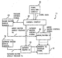
- a display panel drive system to which the present invention is applied will be described with reference to Fig. 1. Specifically, a drive system for a display panel having organic EL elements as light emitting elements will be described.
- the organic EL display panel 10 has a number of organic EL elements arranged in a matrix.
- the organic EL elements on the display panel are driven by an anode driver IC 20 and a cathode driver IC 30 so that the organic EL elements light up.
- the driver ICs 20 and 30 are controlled by control signals from a control circuit 40.
- the control circuit 40 is principally constituted by a microcomputer, a memory circuit and peripheral circuits therefore (not shown).
- the memory circuit includes memory elements such as a RAM and a ROM.
- Programs for controlling the various operations of the display panel drive system 15 are stored in the memory circuit of the control circuit 40 , and the microcomputer of the control circuit 40 executes these programs at a predetermined timing. If there is a large number of organic EL elements provided on the panel, the control circuit 40 may further contain a dedicated display processing controller for performing display processing exclusively in order to decrease the processing by the microcomputer. Alternatively, a separate display processing controller IC may be provided in addition to the microcomputer.
- the pixel data ROM circuit 50 is a storage circuit for storing pixel data which is displayed on the organic EL display panel 10.
- the control circuit 40 reads pixel data from the pixel data storage circuit 50 at a predetermined timing, and the pixel data are used for the display data displayed on the organic EL display panel 10.
- An anode driver supply circuit 60 and a cathode driver supply circuit 70 are supply circuits (power source circuits) for supplying voltages to the driver ICs 20 and 30 so as to drive the organic EL elements.
- the anode driver voltage Va is supplied to the anode driver IC 20 by the anode driver supply circuit 60, while a cathode driver voltage Vc is supplied to the cathode driver IC 30 by the cathode driver supply circuit 70.
- the value of the supply voltage Va is regulated by a voltage control signal from the control circuit 40.
- the organic EL display panel 10 shown in Fig. 2 has a so-called simple matrix constitution, i.e., the organic EL elements are arranged in a matrix shape on the panel to form the "n row x m column" matrix.
- a simple matrix configuration is generally adopted for a part color organic EL display panel so as to reduce product costs.
- Each organic EL element has an organic EL light emission layer sandwiched between an anode electrode and a cathode electrode, and possesses a current rectification characteristic like that of an ordinary diode.
- the anodes of the organic EL elements are line-concentrated for each of the columns and connected to the anode driver IC 20
- the cathodes of the organic EL elements are line-concentrated for each of the rows and connected to the cathode driver IC 30.
- the anode driver IC 20 includes switch elements Sal to Sam, constant current circuits CCg and pull-down resistors Ra.
- One switch element is associated with one constant current circuit CCg and one pull-down resistor Ra.
- the switching operations of the switch elements Sal to Sam are controlled by anode driver control signals supplied from the control circuit 40.
- the output-stage transistor of the constant current circuit CCg is, for example, a PMOS-FET.
- the constant current circuit CCg generates an organic EL element drive current Idrv on the basis of the voltage Va supplied by the anode driver supply circuit 60.
- the cathode driver IC 30 includes switch elements Scl to Scn, pull-up resistors Rc and pull-down resistors Rg.
- One switch element is associated with one pull-up resistor Rc and one pull-down resistor Rg.
- the switching operations of the switch elements Scl to Scn are controlled by cathode driver control signals supplied from the control circuit 40.
- the control circuit 40 supplies the cathode driver control signal, which selects a desired scan line (horizontal display line) from 1 to n rows, to the cathode driver IC 30.
- the cathode driver IC 30 switches the switch element, which corresponds to the line (row) designated by the control signal, from the pull-up resistor Rc side to the pull-down resistor Rg side.
- the second row is selected as the scan line.
- the control circuit 40 reads the pixel data required for the selected scan line(s) from the pixel data ROM circuit 50 and edits (prepares) display data. The control circuit 40 then supplies the display data to the anode driver IC 20 as the anode driver control signal.
- the anode driver IC 20 switches the switch elements of the columns on the panel which are to be lit from the pull-down resistor Rg side to the constant current circuit CCg side on the basis of the control signal.
- the control signal instructs lighting of the first column and the mth column.
- the switch elements Sal and Sam are switched over from the pull-down resistor Ra side to the constant current circuit CCg side, while other switch elements are all set to the pull-down resistor Ra side.
- the drive current Idrv flows to the organic EL elements of the first column and the mth column in the second row on the panel, so that these organic EL elements emit light.
- the anodes of the other organic EL elements are grounded via the pull-down resistors Ra in the anode driver IC 20 while the cathodes of these EL elements are pulled up to the supply voltage Vc via the pull-up resistors Rc in the cathode driver IC 30, and therefore these organic EL elements do not light up.
- the cathode driver IC 30 sequentially scans at a predetermined scanning timing and the anode driver IC 20 receives the display data for the respective scan lines in sync with the scanning timing, thereby displaying a desired image on the organic EL display panel 10.
- Figs. 3A to 3D is a set of time charts that show the display data (which designates EL elements to be lit) for the scan lines of the organic EL display panel 10, and the change in the voltage Va supplied to the anode driver IC 20.
- Fig. 3A shows a line scanning pulse for scanning lines of 1 to n rows of the organic EL display panel 10.
- Fig. 3B shows display data which is set in the buffer memory of the control circuit 40.
- Fig. 3C shows the change in the voltage Va supplied from the anode driver supply circuit 60 to the anode driver IC 20.
- Fig. 3D shows display data which is set in the register in the anode driver IC 20.
- Fig. 3D shows the actual lit states of the organic EL elements on the display lines.
- the line scanning pulse shown in Fig. 3A is supplied each time one line of the organic EL display panel 10 is scanned on the basis of instructions from the control circuit 40. That is, the line scanning of the cathode driver IC 30 is performed in the pulse cycles shown in Fig. 3A.
- the control circuit 40 reads pixel data from the pixel data ROM circuit by accessing the pixel data ROM circuit at an arbitrary timing (e.g., at the rising edge of the line scanning pulse in Fig. 3A) .
- the control circuit 40 then generates display data to be displayed in the next scan line, stores this display data in the buffer memory provided in the control circuit 40, and transfers the display data to the anode driver IC 20 (Fig. 3B).
- the control circuit 40 calculates the lighting rate of the display data at the same time the display data is generated.
- the control circuit 40 generates a voltage control signal which is supplied to the anode driver supply circuit 60 on the basis of the lighting rate thus calculated.
- the anode driver supply circuit 60 gets the voltage control signal from the control circuit 40 and determines the value of the supply voltage that is supplied to the anode driver IC 20.
- another equation or function for deriving the supply voltage Va( ⁇ ) from the lighting rate ⁇ may be established beforehand, and the supply voltage Va( ⁇ ) may be calculated from this equation.
- a conversion table which indicates (pre-fixes) the relationship between the lighting rate ⁇ and the supply voltage Va( ⁇ ) may be prepared, and the supply voltage Va(a) may be determined by using this table.
- the anode driver IC 20 also receives the display data from the buffer memory of the control circuit 40 when the next line scanning pulse rises (Fig. 3B), and latches the display data into the register of the anode driver IC 20 (Fig. 3D).
- the voltage supplied to the anode driver IC 20 is regulated by the lighting rate of the display data such that the higher the lighting rate, the higher the supply voltage is set. Consequently, the drain-source voltage Vds of the output-stage transistor of the constant current circuit of the anode driver IC 20 can always be kept at the appropriate value and hence wasteful power consumption by this transistor can be suppressed. At the same time, the heat generation of the anode driver IC 20 is suppressed, or unnecessary heat generation occurs.
- the supply voltage supplied to the anode driver IC 20 is controlled each time a single line of the display screen is scanned, but the present invention is not limited to or by this example.
- a buffer memory that is capable of storing display data for a plurality of rows (i.e., a plurality of display lines) may be provided in the control circuit 40 .
- the display data may be first stored in this buffer memory, the lighting rate for the whole of this stored data may be calculated, and control of the supply voltage Va for these lines may be performed on the basis of the lighting rate.
- the capacity of the buffer memory may be increased, the display data of a whole frame may be stored in the buffer memory, the lighting rate for the display data of a whole frame may be calculated, and control of the supply voltage Va may be carried out for each frame.
- a large-capacity buffer memory may be provided, the display data of plurality of frames may be stored in this buffer memory, the lighting rate for the display data of the frames may be calculated, and control of the supply voltage Va may be performed for the frames.
- a fluctuation range of the lighting rates for several lines or frames may be detected, and control of the supply voltage Va may be carried out only when this fluctuation range exceeds a predetermined threshold value.
- the supply voltage control for the line may be combined with the supply voltage control for the frame in accordance with the lighting rate fluctuation range.
- organic EL elements are used as light emitting elements in the above embodiment, the present invention is not limited to or by this example.
Landscapes
- Engineering & Computer Science (AREA)
- Physics & Mathematics (AREA)
- Computer Hardware Design (AREA)
- General Physics & Mathematics (AREA)
- Theoretical Computer Science (AREA)
- Electroluminescent Light Sources (AREA)
- Control Of Indicators Other Than Cathode Ray Tubes (AREA)
- Control Of El Displays (AREA)
Applications Claiming Priority (2)
| Application Number | Priority Date | Filing Date | Title |
|---|---|---|---|
| JP2002305948 | 2002-10-21 | ||
| JP2002305948A JP2004138976A (ja) | 2002-10-21 | 2002-10-21 | 表示パネル駆動装置 |
Publications (2)
| Publication Number | Publication Date |
|---|---|
| EP1414008A2 true EP1414008A2 (fr) | 2004-04-28 |
| EP1414008A3 EP1414008A3 (fr) | 2006-03-08 |
Family
ID=32064286
Family Applications (1)
| Application Number | Title | Priority Date | Filing Date |
|---|---|---|---|
| EP03023848A Withdrawn EP1414008A3 (fr) | 2002-10-21 | 2003-10-20 | Système de commande pour un panneau d' affichage émettent de la lumière |
Country Status (3)
| Country | Link |
|---|---|
| US (1) | US20040080473A1 (fr) |
| EP (1) | EP1414008A3 (fr) |
| JP (1) | JP2004138976A (fr) |
Families Citing this family (15)
| Publication number | Priority date | Publication date | Assignee | Title |
|---|---|---|---|---|
| US20050180083A1 (en) | 2002-04-26 | 2005-08-18 | Toshiba Matsushita Display Technology Co., Ltd. | Drive circuit for el display panel |
| JP4302104B2 (ja) * | 2003-05-28 | 2009-07-22 | 三菱電機株式会社 | 電流供給回路および電流供給回路を備える表示装置 |
| JP2005055726A (ja) * | 2003-08-06 | 2005-03-03 | Toshiba Matsushita Display Technology Co Ltd | El表示装置 |
| JP4491207B2 (ja) * | 2003-08-22 | 2010-06-30 | 富士フイルム株式会社 | ディスプレイ表示装置及びディスプレイ表示装置の駆動方法 |
| JP4589614B2 (ja) * | 2003-10-28 | 2010-12-01 | 株式会社 日立ディスプレイズ | 画像表示装置 |
| US7298351B2 (en) * | 2004-07-01 | 2007-11-20 | Leadia Technology, Inc. | Removing crosstalk in an organic light-emitting diode display |
| CN100433099C (zh) * | 2004-07-21 | 2008-11-12 | 松下电器产业株式会社 | 等离子显示装置 |
| US7710356B2 (en) | 2004-07-21 | 2010-05-04 | Panasonic Corporation | Plasma display device |
| JP4743685B2 (ja) * | 2005-01-06 | 2011-08-10 | 東北パイオニア株式会社 | 発光表示パネルの駆動装置および駆動方法 |
| JP2006215097A (ja) * | 2005-02-01 | 2006-08-17 | Tohoku Pioneer Corp | 発光表示パネルの駆動装置および駆動方法 |
| JP4716310B2 (ja) * | 2005-03-03 | 2011-07-06 | 東北パイオニア株式会社 | 発光表示パネルの駆動装置および駆動方法 |
| JP2007114308A (ja) * | 2005-10-18 | 2007-05-10 | Tohoku Pioneer Corp | 発光表示パネルの駆動装置および駆動方法 |
| JP2007114309A (ja) * | 2005-10-18 | 2007-05-10 | Tohoku Pioneer Corp | 発光表示パネルの駆動装置および駆動方法 |
| JP2009069555A (ja) * | 2007-09-14 | 2009-04-02 | Pioneer Electronic Corp | 自発光表示パネルの駆動装置、電子機器および自発光表示パネルの駆動方法 |
| JP2013097169A (ja) * | 2011-11-01 | 2013-05-20 | Mitsubishi Electric Corp | 表示ユニットの駆動装置 |
Family Cites Families (6)
| Publication number | Priority date | Publication date | Assignee | Title |
|---|---|---|---|---|
| US5075596A (en) * | 1990-10-02 | 1991-12-24 | United Technologies Corporation | Electroluminescent display brightness compensation |
| JP2000020004A (ja) * | 1998-06-26 | 2000-01-21 | Mitsubishi Electric Corp | 画像表示装置 |
| JP2000181382A (ja) * | 1998-12-10 | 2000-06-30 | Matsushita Electric Ind Co Ltd | Led式行先表示装置 |
| JP4073107B2 (ja) * | 1999-03-18 | 2008-04-09 | 三洋電機株式会社 | アクティブ型el表示装置 |
| JP2002175046A (ja) * | 2000-12-07 | 2002-06-21 | Sony Corp | 画像表示装置 |
| JP2003150115A (ja) * | 2001-08-29 | 2003-05-23 | Seiko Epson Corp | 電流生成回路、半導体集積回路、電気光学装置および電子機器 |
-
2002
- 2002-10-21 JP JP2002305948A patent/JP2004138976A/ja not_active Withdrawn
-
2003
- 2003-10-20 EP EP03023848A patent/EP1414008A3/fr not_active Withdrawn
- 2003-10-21 US US10/688,981 patent/US20040080473A1/en not_active Abandoned
Also Published As
| Publication number | Publication date |
|---|---|
| JP2004138976A (ja) | 2004-05-13 |
| EP1414008A3 (fr) | 2006-03-08 |
| US20040080473A1 (en) | 2004-04-29 |
Similar Documents
| Publication | Publication Date | Title |
|---|---|---|
| EP1480195B1 (fr) | Procédé d'affichage d'images sur un grand écran d'affichage à diodes organique luminescentes et l'afficheur utilisé à cet effet | |
| EP1414008A2 (fr) | Système de commande pour un panneau d' affichage émettent de la lumière | |
| US7777738B2 (en) | Active matrix display with reduction of power consumption | |
| KR101615393B1 (ko) | 표시 장치 및 그 구동 방법 | |
| CN101751866B (zh) | 用于面板显示装置的背光亮度控制 | |
| US7262753B2 (en) | Method and system for measuring and controlling an OLED display element for improved lifetime and light output | |
| US20070132674A1 (en) | Driving method of self-luminous type display unit, display control device of self-luminous type display unit, current output type drive circuit of self-luminous type display unit | |
| EP2398013B1 (fr) | Dispositif d'affichage comprenant une unité pour calculer la température découvrant le chute de tension directe d'une DEL utilisé comme l'unité d'illumination | |
| US6650307B1 (en) | Method of driving display panel and panel display apparatus | |
| US7561147B2 (en) | Current output type of semiconductor circuit, source driver for display drive, display device, and current output method | |
| US8330684B2 (en) | Organic light emitting display and its driving method | |
| US8803869B2 (en) | Display device and method of driving display device | |
| JP3404357B2 (ja) | 平面ディスプレイ装置の明るさ制御装置及び方法 | |
| JP2006091681A (ja) | 表示装置及び表示方法 | |
| US20060208974A1 (en) | Organic electroluminescent device, driving method thereof and electronic apparatus | |
| US11132949B2 (en) | Compensation method of display device | |
| US7277105B2 (en) | Drive control apparatus and method for matrix panel | |
| US20020190934A1 (en) | Drive unit for a luminescence display panel | |
| JP2006523322A (ja) | 表示装置、及びこのような装置の表示画素のスパークリング方法 | |
| US20240135889A1 (en) | Driving Controlling Device And Driving Controlling Method As Well As Information Processing System | |
| WO2005109903A1 (fr) | Dispositif d'affichage couleur | |
| KR20120061542A (ko) | 발광다이오드 백라이트 및 이를 포함하는 액정표시장치 | |
| CN115050317B (zh) | 数据驱动电路、显示模组以及输出驱动信号的方法 | |
| JP2005338294A (ja) | 有機elディスプレイ装置の駆動装置 | |
| CN118942387A (zh) | Led显示装置的驱动方法及相关装置 |
Legal Events
| Date | Code | Title | Description |
|---|---|---|---|
| PUAI | Public reference made under article 153(3) epc to a published international application that has entered the european phase |
Free format text: ORIGINAL CODE: 0009012 |
|
| AK | Designated contracting states |
Kind code of ref document: A2 Designated state(s): AT BE BG CH CY CZ DE DK EE ES FI FR GB GR HU IE IT LI LU MC NL PT RO SE SI SK TR |
|
| AX | Request for extension of the european patent |
Extension state: AL LT LV MK |
|
| PUAL | Search report despatched |
Free format text: ORIGINAL CODE: 0009013 |
|
| AK | Designated contracting states |
Kind code of ref document: A3 Designated state(s): AT BE BG CH CY CZ DE DK EE ES FI FR GB GR HU IE IT LI LU MC NL PT RO SE SI SK TR |
|
| AX | Request for extension of the european patent |
Extension state: AL LT LV MK |
|
| RIC1 | Information provided on ipc code assigned before grant |
Ipc: G09G 3/30 20060101ALI20060118BHEP Ipc: G09G 3/32 20060101AFI20040128BHEP |
|
| 17P | Request for examination filed |
Effective date: 20060418 |
|
| 17Q | First examination report despatched |
Effective date: 20060630 |
|
| AKX | Designation fees paid |
Designated state(s): DE FR GB |
|
| STAA | Information on the status of an ep patent application or granted ep patent |
Free format text: STATUS: THE APPLICATION IS DEEMED TO BE WITHDRAWN |
|
| 18D | Application deemed to be withdrawn |
Effective date: 20061111 |