EP1414083A1 - Dispositif de stockage de poudre - Google Patents
Dispositif de stockage de poudre Download PDFInfo
- Publication number
- EP1414083A1 EP1414083A1 EP02755728A EP02755728A EP1414083A1 EP 1414083 A1 EP1414083 A1 EP 1414083A1 EP 02755728 A EP02755728 A EP 02755728A EP 02755728 A EP02755728 A EP 02755728A EP 1414083 A1 EP1414083 A1 EP 1414083A1
- Authority
- EP
- European Patent Office
- Prior art keywords
- sealing bag
- sheet
- aqueous electrolyte
- spacers
- face
- Prior art date
- Legal status (The legal status is an assumption and is not a legal conclusion. Google has not performed a legal analysis and makes no representation as to the accuracy of the status listed.)
- Withdrawn
Links
- 238000003860 storage Methods 0.000 title claims abstract description 60
- 239000011255 nonaqueous electrolyte Substances 0.000 claims abstract description 135
- 238000007789 sealing Methods 0.000 claims abstract description 118
- 125000006850 spacer group Chemical group 0.000 claims abstract description 90
- 238000010248 power generation Methods 0.000 claims abstract description 55
- 239000011091 composite packaging material Substances 0.000 claims abstract description 28
- 239000003792 electrolyte Substances 0.000 claims abstract description 16
- 229920003002 synthetic resin Polymers 0.000 claims abstract description 14
- 239000000057 synthetic resin Substances 0.000 claims abstract description 14
- 230000035515 penetration Effects 0.000 claims description 8
- 229920000098 polyolefin Polymers 0.000 claims description 6
- 239000004035 construction material Substances 0.000 claims description 5
- QVGXLLKOCUKJST-UHFFFAOYSA-N atomic oxygen Chemical compound [O] QVGXLLKOCUKJST-UHFFFAOYSA-N 0.000 claims description 4
- 229910052760 oxygen Inorganic materials 0.000 claims description 4
- 239000001301 oxygen Substances 0.000 claims description 4
- 229920000106 Liquid crystal polymer Polymers 0.000 claims description 2
- 239000004977 Liquid-crystal polymers (LCPs) Substances 0.000 claims description 2
- 229920000642 polymer Polymers 0.000 claims description 2
- 239000010410 layer Substances 0.000 description 60
- 239000011888 foil Substances 0.000 description 19
- 229910052782 aluminium Inorganic materials 0.000 description 18
- XAGFODPZIPBFFR-UHFFFAOYSA-N aluminium Chemical compound [Al] XAGFODPZIPBFFR-UHFFFAOYSA-N 0.000 description 18
- 239000003990 capacitor Substances 0.000 description 14
- 238000005452 bending Methods 0.000 description 13
- 238000004519 manufacturing process Methods 0.000 description 9
- 238000000034 method Methods 0.000 description 9
- 239000012212 insulator Substances 0.000 description 8
- -1 polypropylene Polymers 0.000 description 8
- 239000008151 electrolyte solution Substances 0.000 description 7
- 239000004020 conductor Substances 0.000 description 5
- OKTJSMMVPCPJKN-UHFFFAOYSA-N Carbon Chemical compound [C] OKTJSMMVPCPJKN-UHFFFAOYSA-N 0.000 description 4
- PXHVJJICTQNCMI-UHFFFAOYSA-N Nickel Chemical compound [Ni] PXHVJJICTQNCMI-UHFFFAOYSA-N 0.000 description 4
- 239000004698 Polyethylene Substances 0.000 description 4
- 229920000573 polyethylene Polymers 0.000 description 4
- 239000000758 substrate Substances 0.000 description 4
- 238000003466 welding Methods 0.000 description 4
- RYGMFSIKBFXOCR-UHFFFAOYSA-N Copper Chemical compound [Cu] RYGMFSIKBFXOCR-UHFFFAOYSA-N 0.000 description 3
- OIFBSDVPJOWBCH-UHFFFAOYSA-N Diethyl carbonate Chemical compound CCOC(=O)OCC OIFBSDVPJOWBCH-UHFFFAOYSA-N 0.000 description 3
- KMTRUDSVKNLOMY-UHFFFAOYSA-N Ethylene carbonate Chemical compound O=C1OCCO1 KMTRUDSVKNLOMY-UHFFFAOYSA-N 0.000 description 3
- LYCAIKOWRPUZTN-UHFFFAOYSA-N Ethylene glycol Chemical compound OCCO LYCAIKOWRPUZTN-UHFFFAOYSA-N 0.000 description 3
- HBBGRARXTFLTSG-UHFFFAOYSA-N Lithium ion Chemical compound [Li+] HBBGRARXTFLTSG-UHFFFAOYSA-N 0.000 description 3
- 239000004743 Polypropylene Substances 0.000 description 3
- 239000002253 acid Substances 0.000 description 3
- 239000000853 adhesive Substances 0.000 description 3
- 230000001070 adhesive effect Effects 0.000 description 3
- 229910001416 lithium ion Inorganic materials 0.000 description 3
- 239000003960 organic solvent Substances 0.000 description 3
- 229920013716 polyethylene resin Polymers 0.000 description 3
- 229920001155 polypropylene Polymers 0.000 description 3
- 229920005989 resin Polymers 0.000 description 3
- 239000011347 resin Substances 0.000 description 3
- XLYOFNOQVPJJNP-UHFFFAOYSA-N water Substances O XLYOFNOQVPJJNP-UHFFFAOYSA-N 0.000 description 3
- 229910001290 LiPF6 Inorganic materials 0.000 description 2
- 239000011248 coating agent Substances 0.000 description 2
- 238000000576 coating method Methods 0.000 description 2
- 230000000052 comparative effect Effects 0.000 description 2
- 239000011889 copper foil Substances 0.000 description 2
- 230000007797 corrosion Effects 0.000 description 2
- 238000005260 corrosion Methods 0.000 description 2
- 229920001903 high density polyethylene Polymers 0.000 description 2
- 239000004700 high-density polyethylene Substances 0.000 description 2
- 238000001746 injection moulding Methods 0.000 description 2
- 238000003475 lamination Methods 0.000 description 2
- 239000000463 material Substances 0.000 description 2
- 229910052751 metal Inorganic materials 0.000 description 2
- 239000002184 metal Substances 0.000 description 2
- 239000007769 metal material Substances 0.000 description 2
- 239000005022 packaging material Substances 0.000 description 2
- 229910000838 Al alloy Inorganic materials 0.000 description 1
- 229920002799 BoPET Polymers 0.000 description 1
- VYZAMTAEIAYCRO-UHFFFAOYSA-N Chromium Chemical compound [Cr] VYZAMTAEIAYCRO-UHFFFAOYSA-N 0.000 description 1
- JOYRKODLDBILNP-UHFFFAOYSA-N Ethyl urethane Chemical compound CCOC(N)=O JOYRKODLDBILNP-UHFFFAOYSA-N 0.000 description 1
- 238000003109 Karl Fischer titration Methods 0.000 description 1
- 229910032387 LiCoO2 Inorganic materials 0.000 description 1
- WHXSMMKQMYFTQS-UHFFFAOYSA-N Lithium Chemical compound [Li] WHXSMMKQMYFTQS-UHFFFAOYSA-N 0.000 description 1
- 239000004677 Nylon Substances 0.000 description 1
- 239000004952 Polyamide Substances 0.000 description 1
- RTAQQCXQSZGOHL-UHFFFAOYSA-N Titanium Chemical compound [Ti] RTAQQCXQSZGOHL-UHFFFAOYSA-N 0.000 description 1
- 239000006230 acetylene black Substances 0.000 description 1
- 239000011149 active material Substances 0.000 description 1
- 239000012790 adhesive layer Substances 0.000 description 1
- 239000010405 anode material Substances 0.000 description 1
- 230000003466 anti-cipated effect Effects 0.000 description 1
- 230000015572 biosynthetic process Effects 0.000 description 1
- 239000010406 cathode material Substances 0.000 description 1
- 229910052804 chromium Inorganic materials 0.000 description 1
- 239000011651 chromium Substances 0.000 description 1
- 238000010276 construction Methods 0.000 description 1
- 229910052802 copper Inorganic materials 0.000 description 1
- 239000010949 copper Substances 0.000 description 1
- 238000004132 cross linking Methods 0.000 description 1
- 229920003020 cross-linked polyethylene Polymers 0.000 description 1
- 239000004703 cross-linked polyethylene Substances 0.000 description 1
- 238000005520 cutting process Methods 0.000 description 1
- 230000007423 decrease Effects 0.000 description 1
- 230000006866 deterioration Effects 0.000 description 1
- IEJIGPNLZYLLBP-UHFFFAOYSA-N dimethyl carbonate Chemical compound COC(=O)OC IEJIGPNLZYLLBP-UHFFFAOYSA-N 0.000 description 1
- 238000009820 dry lamination Methods 0.000 description 1
- 229920006351 engineering plastic Polymers 0.000 description 1
- JBTWLSYIZRCDFO-UHFFFAOYSA-N ethyl methyl carbonate Chemical compound CCOC(=O)OC JBTWLSYIZRCDFO-UHFFFAOYSA-N 0.000 description 1
- 238000011156 evaluation Methods 0.000 description 1
- 238000001125 extrusion Methods 0.000 description 1
- 230000005251 gamma ray Effects 0.000 description 1
- 239000011521 glass Substances 0.000 description 1
- 229910002804 graphite Inorganic materials 0.000 description 1
- 239000010439 graphite Substances 0.000 description 1
- 238000010438 heat treatment Methods 0.000 description 1
- 239000012943 hotmelt Substances 0.000 description 1
- 230000005865 ionizing radiation Effects 0.000 description 1
- 230000001678 irradiating effect Effects 0.000 description 1
- 238000004898 kneading Methods 0.000 description 1
- 229910052744 lithium Inorganic materials 0.000 description 1
- MHCFAGZWMAWTNR-UHFFFAOYSA-M lithium perchlorate Chemical compound [Li+].[O-]Cl(=O)(=O)=O MHCFAGZWMAWTNR-UHFFFAOYSA-M 0.000 description 1
- 229910001486 lithium perchlorate Inorganic materials 0.000 description 1
- 229910003002 lithium salt Inorganic materials 0.000 description 1
- 159000000002 lithium salts Chemical class 0.000 description 1
- 229910001537 lithium tetrachloroaluminate Inorganic materials 0.000 description 1
- 229910001496 lithium tetrafluoroborate Inorganic materials 0.000 description 1
- 230000013011 mating Effects 0.000 description 1
- 238000002844 melting Methods 0.000 description 1
- 230000008018 melting Effects 0.000 description 1
- 239000000203 mixture Substances 0.000 description 1
- 238000000465 moulding Methods 0.000 description 1
- 229910052759 nickel Inorganic materials 0.000 description 1
- 239000004745 nonwoven fabric Substances 0.000 description 1
- 229920001778 nylon Polymers 0.000 description 1
- 238000007254 oxidation reaction Methods 0.000 description 1
- 229920002647 polyamide Polymers 0.000 description 1
- 229920005672 polyolefin resin Polymers 0.000 description 1
- 239000004810 polytetrafluoroethylene Substances 0.000 description 1
- 229920001343 polytetrafluoroethylene Polymers 0.000 description 1
- 230000002265 prevention Effects 0.000 description 1
- RUOJZAUFBMNUDX-UHFFFAOYSA-N propylene carbonate Chemical compound CC1COC(=O)O1 RUOJZAUFBMNUDX-UHFFFAOYSA-N 0.000 description 1
- 238000005096 rolling process Methods 0.000 description 1
- 150000003839 salts Chemical class 0.000 description 1
- 239000000243 solution Substances 0.000 description 1
- 239000011877 solvent mixture Substances 0.000 description 1
- 230000003068 static effect Effects 0.000 description 1
- 238000010998 test method Methods 0.000 description 1
- 229920002397 thermoplastic olefin Polymers 0.000 description 1
- 229920005992 thermoplastic resin Polymers 0.000 description 1
- WYXIGTJNYDDFFH-UHFFFAOYSA-Q triazanium;borate Chemical compound [NH4+].[NH4+].[NH4+].[O-]B([O-])[O-] WYXIGTJNYDDFFH-UHFFFAOYSA-Q 0.000 description 1
- 238000009816 wet lamination Methods 0.000 description 1
Images






Classifications
-
- H—ELECTRICITY
- H01—ELECTRIC ELEMENTS
- H01G—CAPACITORS; CAPACITORS, RECTIFIERS, DETECTORS, SWITCHING DEVICES, LIGHT-SENSITIVE OR TEMPERATURE-SENSITIVE DEVICES OF THE ELECTROLYTIC TYPE
- H01G9/00—Electrolytic capacitors, rectifiers, detectors, switching devices, light-sensitive or temperature-sensitive devices; Processes of their manufacture
- H01G9/004—Details
- H01G9/08—Housing; Encapsulation
-
- H—ELECTRICITY
- H01—ELECTRIC ELEMENTS
- H01G—CAPACITORS; CAPACITORS, RECTIFIERS, DETECTORS, SWITCHING DEVICES, LIGHT-SENSITIVE OR TEMPERATURE-SENSITIVE DEVICES OF THE ELECTROLYTIC TYPE
- H01G9/00—Electrolytic capacitors, rectifiers, detectors, switching devices, light-sensitive or temperature-sensitive devices; Processes of their manufacture
- H01G9/004—Details
- H01G9/08—Housing; Encapsulation
- H01G9/10—Sealing, e.g. of lead-in wires
-
- H—ELECTRICITY
- H01—ELECTRIC ELEMENTS
- H01M—PROCESSES OR MEANS, e.g. BATTERIES, FOR THE DIRECT CONVERSION OF CHEMICAL ENERGY INTO ELECTRICAL ENERGY
- H01M50/00—Constructional details or processes of manufacture of the non-active parts of electrochemical cells other than fuel cells, e.g. hybrid cells
- H01M50/10—Primary casings; Jackets or wrappings
- H01M50/116—Primary casings; Jackets or wrappings characterised by the material
- H01M50/124—Primary casings; Jackets or wrappings characterised by the material having a layered structure
- H01M50/126—Primary casings; Jackets or wrappings characterised by the material having a layered structure comprising three or more layers
-
- H—ELECTRICITY
- H01—ELECTRIC ELEMENTS
- H01M—PROCESSES OR MEANS, e.g. BATTERIES, FOR THE DIRECT CONVERSION OF CHEMICAL ENERGY INTO ELECTRICAL ENERGY
- H01M50/00—Constructional details or processes of manufacture of the non-active parts of electrochemical cells other than fuel cells, e.g. hybrid cells
- H01M50/10—Primary casings; Jackets or wrappings
- H01M50/172—Arrangements of electric connectors penetrating the casing
- H01M50/174—Arrangements of electric connectors penetrating the casing adapted for the shape of the cells
- H01M50/178—Arrangements of electric connectors penetrating the casing adapted for the shape of the cells for pouch or flexible bag cells
-
- H—ELECTRICITY
- H01—ELECTRIC ELEMENTS
- H01M—PROCESSES OR MEANS, e.g. BATTERIES, FOR THE DIRECT CONVERSION OF CHEMICAL ENERGY INTO ELECTRICAL ENERGY
- H01M50/00—Constructional details or processes of manufacture of the non-active parts of electrochemical cells other than fuel cells, e.g. hybrid cells
- H01M50/50—Current conducting connections for cells or batteries
- H01M50/543—Terminals
- H01M50/547—Terminals characterised by the disposition of the terminals on the cells
- H01M50/55—Terminals characterised by the disposition of the terminals on the cells on the same side of the cell
-
- H—ELECTRICITY
- H01—ELECTRIC ELEMENTS
- H01M—PROCESSES OR MEANS, e.g. BATTERIES, FOR THE DIRECT CONVERSION OF CHEMICAL ENERGY INTO ELECTRICAL ENERGY
- H01M50/00—Constructional details or processes of manufacture of the non-active parts of electrochemical cells other than fuel cells, e.g. hybrid cells
- H01M50/50—Current conducting connections for cells or batteries
- H01M50/543—Terminals
- H01M50/552—Terminals characterised by their shape
- H01M50/553—Terminals adapted for prismatic, pouch or rectangular cells
-
- H—ELECTRICITY
- H01—ELECTRIC ELEMENTS
- H01M—PROCESSES OR MEANS, e.g. BATTERIES, FOR THE DIRECT CONVERSION OF CHEMICAL ENERGY INTO ELECTRICAL ENERGY
- H01M10/00—Secondary cells; Manufacture thereof
- H01M10/05—Accumulators with non-aqueous electrolyte
-
- H—ELECTRICITY
- H01—ELECTRIC ELEMENTS
- H01M—PROCESSES OR MEANS, e.g. BATTERIES, FOR THE DIRECT CONVERSION OF CHEMICAL ENERGY INTO ELECTRICAL ENERGY
- H01M50/00—Constructional details or processes of manufacture of the non-active parts of electrochemical cells other than fuel cells, e.g. hybrid cells
- H01M50/10—Primary casings; Jackets or wrappings
- H01M50/116—Primary casings; Jackets or wrappings characterised by the material
- H01M50/124—Primary casings; Jackets or wrappings characterised by the material having a layered structure
-
- H—ELECTRICITY
- H01—ELECTRIC ELEMENTS
- H01M—PROCESSES OR MEANS, e.g. BATTERIES, FOR THE DIRECT CONVERSION OF CHEMICAL ENERGY INTO ELECTRICAL ENERGY
- H01M6/00—Primary cells; Manufacture thereof
- H01M6/04—Cells with aqueous electrolyte
- H01M6/06—Dry cells, i.e. cells wherein the electrolyte is rendered non-fluid
- H01M6/12—Dry cells, i.e. cells wherein the electrolyte is rendered non-fluid with flat electrodes
-
- Y—GENERAL TAGGING OF NEW TECHNOLOGICAL DEVELOPMENTS; GENERAL TAGGING OF CROSS-SECTIONAL TECHNOLOGIES SPANNING OVER SEVERAL SECTIONS OF THE IPC; TECHNICAL SUBJECTS COVERED BY FORMER USPC CROSS-REFERENCE ART COLLECTIONS [XRACs] AND DIGESTS
- Y02—TECHNOLOGIES OR APPLICATIONS FOR MITIGATION OR ADAPTATION AGAINST CLIMATE CHANGE
- Y02E—REDUCTION OF GREENHOUSE GAS [GHG] EMISSIONS, RELATED TO ENERGY GENERATION, TRANSMISSION OR DISTRIBUTION
- Y02E60/00—Enabling technologies; Technologies with a potential or indirect contribution to GHG emissions mitigation
- Y02E60/10—Energy storage using batteries
-
- Y—GENERAL TAGGING OF NEW TECHNOLOGICAL DEVELOPMENTS; GENERAL TAGGING OF CROSS-SECTIONAL TECHNOLOGIES SPANNING OVER SEVERAL SECTIONS OF THE IPC; TECHNICAL SUBJECTS COVERED BY FORMER USPC CROSS-REFERENCE ART COLLECTIONS [XRACs] AND DIGESTS
- Y02—TECHNOLOGIES OR APPLICATIONS FOR MITIGATION OR ADAPTATION AGAINST CLIMATE CHANGE
- Y02P—CLIMATE CHANGE MITIGATION TECHNOLOGIES IN THE PRODUCTION OR PROCESSING OF GOODS
- Y02P70/00—Climate change mitigation technologies in the production process for final industrial or consumer products
- Y02P70/50—Manufacturing or production processes characterised by the final manufactured product
Definitions
- the present invention relates to a electric power storage device used as a power source of electronic equipment or the like.
- a power storage device such as an electrolytic capacitor (aluminum electrolytic capacitor, etc.), an electric double layer capacitor, and a non-aqueous electrolyte battery, which include an anode, a cathode, a non-aqueous electrolyte, an anode lead, and a cathode lead, the anode, the cathode, and the non-aqueous electrolyte being enclosed in a sealing bag constituted by using a composite packaging material.
- the non-aqueous electrolyte battery such as a lithium ion secondary battery, taking a form where an anode, a cathode, and an electrolytic solution are enclosed in a small-sized lightweight sealing bag, has high battery voltage and high energy density, and the non-aqueous electrolyte battery is required to be easily miniaturized and reduced in weight. Accordingly, the non-aqueous electrolyte battery is anticipated to be the power source of the above described small-sized electronic equipment.
- non-aqueous electrolyte battery with a constitution using a lightweight sealing bag for enclosing the anode, the cathode, and the non-aqueous electrolyte for the purpose of improving energy density per unit weight of the battery.
- the sealing bag is fabricated by superposing two sheets composed of a composite packaging material including a synthetic resin layer and a metallic layer such as a metallic foil and then by heat-sealing edges thereof or the like.
- the section including the anode, the cathode, and the non-aqueous electrolyte, which are enclosed within the power storage device such as the non-aqueous electrolyte battery, is generally referred to as a "power generation unit" as needed.
- the power generation unit may further include a separator, a collector, or the like.
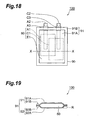
- a non-aqueous electrolyte battery 100 with a structure shown in Figs. 18 and 19 and a non-aqueous electrolyte battery 200 with a structure shown in Figs. 20 and 21
- Fig. 18 is a front view showing a basic constitution of the conventional non-aqueous electrolyte battery 100.
- Fig. 19 is a sectional view taken along a line X-X of Fig. 18.
- Fig. 20 is a front view showing a basic constitution of the conventional non-aqueous electrolyte battery 200.
- Fig. 21 is a sectional view taken along a line X-X of Fig. 20.
- the conventional non-aqueous electrolyte battery 100 shown in Figs. 18 and 19 mainly includes a power generation unit 80 containing an anode A1, a cathode C1, and a non-aqueous electrolyte E1, a sealing bag 90 enclosing the power generation unit 80, an anode lead A2, and a cathode lead C2.
- One end of the anode lead A2 is electrically connected to the anode A1, and the other end is projected out of the sealing bag 90.
- One end of the cathode lead C2 is electrically connected to the cathode C1, and the other end is projected out of the sealing bag 90.
- the sealing bag 90 is formed by sealing edges (that is, an edge 91B in the sheet 91, and an edge 92B in the sheet 92) of the two sheets 91 and 92 facing each other, which are composed of the above described composite packaging material, by means of adhesive or heat sealing.
- the edge of each sheet after being sealed is referred to as a "sealed portion".
- a portion of the anode lead A2 in contact with the sealed portion 91B, 92B and a portion of the cathode lead C2 in contact with the sealed potion 92 are covered with an insulator A3 and an insulator C3, respectively, for preventing contact between these leads and the metallic layer within the composite packaging material.
- FIG. 20 and 21 Another conventional non-aqueous electrolyte battery 200 shown in Figs. 20 and 21 has a similar constitution to the conventional non-aqueous electrolyte battery 100 shown in Figs. 18 and 19 except that with the difference being the sealing bag 90 being different from that of the conventional non-aqueous electrolyte battery 100.
- the sealing bag 90 is formed in the following manner. First, a pair of facing edges of a rectangular sheet 91 composed of a sheet of the composite packaging material are overlapped each other and sealed as a sealed portion 91B to form a tubular body having two openings. Subsequently, edges of the two openings of the tubular body are sealed as sealed portions 91C.
- volume of such dead space increases, the battery energy density per unit volume of space for mounting the battery (hereinafter, referred to as "volumetric energy density on the basis of a volume of space for the battery to be mounted") decreases.
- volumetric energy density of a power storage device such as a battery
- volumetric energy density is defined by a ratio of full output energy from the power generation unit to the volume of the power storage device such as a battery.
- our specification uses a volumetric energy density based on the volume of space for the power storage device such as a battery to be mounted, not based on the volume of the power storage device itself such as a battery.
- the "volumetric energy density on the basis of the volume of the space for the battery to be mounted” means a ratio of full output energy from the power generation unit to an apparent volume of the battery obtained based on a maximum height, a maximum width, and a maximum thickness of the power storage device such as the battery. In fact, it becomes important to improve the volumetric energy density on the basis of the volume of the space for the battery to be mounted, as well as to improve the original definition of volumetric energy density described above.
- Japanese Patent Laid-Open No. 11(1999)-260327 gazette has proposed a non-aqueous electrolyte battery, in which a battery like the above described non-aqueous electrolyte battery 200 is shown, with at least any one of the three sealed portions 91B and 91C folded, and the bent portion designed to be limited within a thickness of a body of an exterior package. Accordingly, this non-aqueous electrolyte battery is intended only to reduce dead space created due to the sealed portions of the sealing bag of the non-aqueous electrolyte battery in the space for mounting the battery within the equipment where the battery is to be used.
- the problems in the above described non-aqueous electrolyte battery were generated similarly in the other power storage devices having a constitution similar to that in the above described non-aqueous electrolyte battery, such as the electrolytic capacitor (aluminum electrolytic capacitor) and the electric double layer capacitor.
- the present invention is made in the light of the problems contained in the above described conventional art.
- An object thereof is to provide a power storage device with high "volumetric energy density on the basis of the volume of space for the device to be mounted".
- the present invention provides a power storage device having a power generation unit including an anode, a cathode, and an electrolyte, a sealing bag for enclosing the power generation unit, an anode lead having one end electrically connected to the anode and the other end projected out of the sealing bag, and a cathode lead having one end electrically connected to the cathode and the other end projected out of the sealing bag.
- the sealing bag includes a first sheet composed of a composite packaging material, and a second sheet composed of the composite packaging material, which face each other, and spacers made of synthetic resin, the spacers being arranged between a face of the first sheet facing the second sheet and a face of the second sheet facing the face of the first sheet to secure space for accommodating the power generation unit. Moreover, the spacers are arranged in edges of the face of the first sheet facing the second sheet.
- the sealing bag is constituted by use of the above described spacers. Accordingly, the dead space created in the space for mounting the device due to the sealed portions of the sealing bag in the conventional power storage device can be sufficiently reduced without lowering strength of the composite packaging material constituting the sealing bag.
- the volume occupied by the power generation unit in the sealing bag can be easily increased, compared to the conventional power storage device. Therefore, a power storage device is able to be provided, which is high in "the volumetric energy density on the basis of the volume of space for the device to be mounted" and capable of efficiently utilizing the space for the device to be mounted.
- the composite packaging material indicates a packaging material including a plurality of layers containing at least a synthetic resin layer and a metallic layer such as a metallic foil.
- the first and second sheets which constitute the sealing bag, may be connected with each other.
- one sheet is folded at the center, and sheet portions having mating faces facing each other may be individually used as the first and second sheets.
- the first and second sheets are continuous, and the sealing bag is formed by bending one sheet. In this way, the sealed portions in the sealing bag can be further reduced, thus improving the volumetric energy density on the basis of "the volume of space for the power storage device to be mounted".
- the spacer may be arranged along a portion where the sheet is bent. Therefore, the mechanical strength of the sealing bag can be improved.
- the sealing bag can accommodate the power generation unit with a larger volume, thus improving the volumetric energy density on the basis of the volume of space for the power storage device to be mounted.
- the power storage device indicates a device of a configuration including a power generation unit which includes an anode, a cathode, and an electrolyte, a sealing bag for enclosing the power generation unit, an anode lead having one end electrically connected to the anode and the other end projected out of the sealing bag, and a cathode lead having one end electrically connected to the cathode and the other end projected out of the sealing bag.
- the power storage device indicates, for example, a non-aqueous electrolyte battery such as the lithium ion secondary battery, the electrolytic capacitor such as the aluminum electrolytic capacitor, and the electric double layer capacitor having polarizable electrodes as the anode and the cathode.
- the power storage device may be a primary battery or a secondary battery.
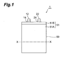
- Fig. 1 is a front view showing a first embodiment of the non-aqueous electrolyte battery as a power storage device of the present invention.
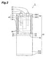
- Fig. 2 is a developed view showing a basic constitution of the non-aqueous electrolyte battery shown in Fig. 1.
- Fig. 3 is a sectional view taken along a line X-X of Fig. 1.
- a non-aqueous electrolyte battery 1 mainly includes a power generation unit 40 containing an anode 10, a cathode 20, and a non-aqueous electrolyte 30, a sealing bag 50 enclosing the power generation unit 40, an anode lead 12, and a cathode lead 22.
- One end of the anode lead 12 is electrically connected to the anode 10, and the other end is projected out of the sealing bag 50.
- One end of the cathode lead 22 is electrically connected to the cathode 20, and the other end is projected out of the sealing bag 50.
- the sealing bag 50 includes a first sheet 51 composed of a composite packaging material, a second sheet 52 composed of a composite packaging material, and a pair of spacers 60 made of synthetic resin for securing space to accommodate the power generation unit 40, the first and second sheets 51 and 52 facing each other of the first sheet 51 facing the second sheet.
- the pair of spacers 60 is arranged between a face F51 of the first sheet 51, facing the second sheet 52, and a face F52 of the second sheet 52, facing the face F51.
- the spacers 60 in a pair are individually arranged at facing positions on edges of the face F51 of the first sheet 51 facing the second sheet.
- the pair of spacers is arranged in the manner, as previously described, dead space in the sealing bag 50, due to shapes of the spacers 60, can be reduced more efficiently. Consequently, the power generation unit 40 of a larger volume can be accommodated in the sealing bag 50, thus improving "the volumetric energy density on the basis of the volume of space for the battery 1 to be mounted".
- the first and second sheets 51 and 52 in this embodiment are connected.
- the sealing bag 50 in this embodiment is formed in a manner that one rectangular sheet composed of a composite packaging material is bent at bending lines X1-X1 and X2-X2 shown in Fig. 2, and a pair of facing edges (in the drawing, an edge 51B of the first sheet 51 and an edge 52B of the second sheet 52) of the rectangular sheet is overlapped and sealed.
- the first and second sheets 51 and 52 denote the sheet portions including the faces (F51 and F52) facing each other, which are formed in bending the rectangular sheet as described above.
- the spacer since the spacer does not necessarily need to be disposed at the bottom portion 53 of the first and second sheets 51 and 52, the bottom portion 53 being formed between the bending lines X1-X1 and X2-X2, thus the sealed portions in the sealing bag 50 can be further reduced. Consequently, the volumetric energy density of the battery 1, on the basis of the volume of the space for the battery 1 to be mounted, can be further improved.
- a distance between the bending lines X1-X1 and X2-X2 is substantially equal to a thickness of the spacers 60.
- a spacer may be disposed along the bottom portion 53 of the first and second sheets 51 and 52, the bottom portion 53 being formed between the bending lines X1-X1 and X2-X2, as needed.
- the construction material of the spacers 60 is not particularly limited as long as the construction material is synthetic resin.
- the construction material of the spacers 60 is any one type of polymer selected from a group consisting of cross-linked polyolefin and liquid crystal polymer.
- the cross-linked polyolefin indicates polyolefin having molecules cross-linked in a three dimensional mesh, which is difficult to dissolve in an organic solvent and difficult to be melted at a temperature other than melting point.
- cross-linked polypropylene or cross-linked polyethylene is further preferred. From the viewpoint of productivity, among the above described cross-linked polyolefin, one cross-linked by irradiation of ionizing radiation is preferred.
- the composite packaging material constituting the first and second sheets 51 and 52 is not particularly limited as long as the packaging material includes a synthetic resin layer or a metallic layer such as a metallic foil.
- the composite packaging material preferably includes three layers or more, containing an innermost layer made of synthetic resin; which is arranged on the innermost side of the sealing bag 50 in contact with the power generation unit 40; an outermost layer made of synthetic resin, which is arranged on a side of an outer surface of the sealing bag 50 farthest from the power generation unit 40; and at least one metallic layer arranged between the innermost layer and the outermost layer.
- a layer formed of a corrosion-resistant metallic material is preferred.
- a metallic foil made of aluminum, an aluminum alloy, titan, chromium, or the like may be used.
- a thermoplastic resin layer made of polyethylene, acid modified polyethylene, polypropylene, acid modified polypropylene, or the like may be used.
- a layer made of engineering plastic such as polyethylene telephthalate (PET), polyamide (nylon) may be used.
- a sealing method for all the sealed portions in the sealing bag 50 including, the sealed portions between the spacers 60 and each of the first and second sheets and the sealed portion of the sealing bag composed of the edge 51B of the first sheet 51 and the edge 52B of the second sheet 52, is preferable, but not particularly limited to, a heat sealing or ultrasonic welding method from the viewpoint of productivity.
- non-aqueous electrolytic solution 50 a solution obtained by dissolving metal salt in an organic solvent is used.
- a solution obtained by dissolving metal salt in an organic solvent is used as lithium salt.
- the organic solvent dimethyl carbonate, diethyl carbonate, ethylene carbonate, methyl ethyl carbonate, or the like is used.
- Each of the anode 10 and the cathode 20 is composed of a metallic substrate (not shown) of a metallic foil or expanded metal, which is called a collector, and an active material layer (not shown) formed on the metallic substrate, which is to be the collector. Between the anode 10 and the cathode 20, a separator (not shown) may be arranged as needed.
- the metallic substrate of the cathode 20 is electrically connected to one end of the cathode lead 22 made of, for example, aluminum. The other end of the cathode lead 22 is extended out of the sealing bag 50.
- the metallic substrate of the anode 10 is electrically connected to one end of the anode lead conductor 12 made of, for example, copper or nickel. The other end of the anode lead conductor 12 is extended out of the sealing bag 14.
- a portion of the anode lead 12 in contact with the sealed portion of the sealing'bag which is composed of the edge 51B of the first sheet 51 and the edge 52B of the second sheet 52, is covered with an insulator 14 for preventing contact between the anode lead 12 and the metallic layer in the composite packaging material constituting each sheet.
- a portion of the cathode lead 22 in contact with the sealed portion of the sealing bag which is composed of the edge 51B of the first sheet 51 and the edge 52B of the second sheet 52, is covered with an insulator 24 for preventing contact between the cathode lead 22 and the metallic layer in the composite packaging material constituting each sheet.
- each of the insulators 14 and 24 may be constituted of a layer 25a made of thermoplastic polyolefin resin, which is adhered to the anode lead 12 or the cathode lead 22, and a layer 25b made of the cross-linked polyolefin resin, which is provided on the outside thereof.
- the composite packaging material constituting the first and second sheets is fabricated by use of a known manufacturing method such as dry lamination, wet lamination, hot melt lamination, or extrusion lamination.
- a film which is a synthetic resin layer that constitutes the composite packaging material and a metallic foil made of aluminum or the like, are prepared.
- the metallic foil can be prepared by rolling process of a metallic material, for example.
- the composite packaging material (multilayer film) is prepared by adhering the metallic foil to the film, which is the synthetic resin layer, with adhesive interposed therebetween or the like.
- the composite packaging material is then cut into a predetermined size to prepare a rectangular sheet.
- the pair of spacers 60 having a predetermined shape and size is prepared by injection molding or the like.
- the pair of spacers 60 is disposed at the side rim of the rectangular sheet.
- the rectangular sheet is then bent as previously described.
- the portions where the sheet and the spacers 60 come into contact with each other are heat-sealed in a desired seal width by use of a sealing machine under a predetermined heating condition.
- the sealing bag 50 in a state having an opening at the top (the portion composed of the edge 51B of the first sheet 51 and the edge 52B of the second sheet 52) is thus obtained.
- the anode 10 and the cathode 20, which constitute the power generation unit 40, and the separator (not shown), as needed, are inserted into the inside of the sealing bag 50, which is in the state having the opening, and then the non-aqueous electrolytic solution 20 is injected. Subsequently, the opening of the sealing bag 50 is sealed by use of a sealing machine in a state where part of the anode lead conductor 12 and part of the cathode lead 22 are inserted in the sealing bag 50. In this way, the fabrication of the sealing bag 50 and the non-aqueous electrolyte battery 1 is completed.
- Fig. 4 is a front view showing a second embodiment of the non-aqueous electrolyte battery as a power storage device according to the present invention.
- Fig. 5 is a developed view showing a basic constitution of the non-aqueous electrolyte battery shown in Fig. 4.
- Fig. 6 is a sectional view taken along a line X-X of Fig. 4, when viewed from the inside of a sealing bag 50.
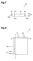
- Fig. 7 is a sectional view taken along a line Y-Y of Fig. 4.
- the sealing bag 50 of the non-aqueous electrolyte battery 2 is formed in a manner where a rectangular sheet composed of a sheet of the composite packaging material is bent at bending lines Y1-Y1 and Y2-Y2 shown in Fig. 5, and the pair of facing edges (the edge 51B of the first sheet 51 and the edge 52B of the second sheet 52) in the inner face of the rectangular sheet is overlapped to be sealed.
- this portion is folded to be brought into close contact with the side face of the sealing bag 50 so as not to protrude from the projected area of the sealing bag 50.
- the spacers 60 in a pair are individually arranged at positions on a pair of edges different from the pair of facing edges of the rectangular sheet described above, among the positions facing each other on the edges of the face F51 of the first sheet 51, facing the second sheet.
- one of the pair of spacers 60 is integrally molded with each of the anode lead 12 and the cathode lead 22 with one end projecting outwardly.
- one of the pair of spacers 60 is formed with two grooves having sectional shapes and sizes adjusted to the sectional shapes and the sizes of the anode lead 12 and the cathode lead 22.
- the anode lead 12 and the cathode lead 22 are fitted in the respective grooves, and the grooves and the respective leads are adhered to each other, for example by use of heat sealing or ultrasonic welding.
- the anode lead and the cathode lead may be integrally molded with the spacer.
- the spacer is disposed at the sealed portion between the sealing bag and each of the anode lead and the cathode lead to be sealed. Accordingly, compared to the case of sealing without the spacer arranged, dead space (for example, the dead space R, R1, and R2 shown in Figs. 19 and 21) outside the sealing bag and dead space (for example, a region R3 shown in Fig. 19 or a region R4 shown in Fig. 21) within the sealing bag can be easily reduced. Furthermore, the strength of the seal between the sealing bag and each of the anode lead and the cathode lead can be easily improved.
- Fig. 8 is a front view showing a third embodiment of the non-aqueous electrolyte battery as the power storage device according to the present invention.
- Fig. 9 is a developed view showing a basic constitution of the non-aqueous electrolyte battery shown in Fig. 8.
- Fig. 10 is a sectional view taken along a line X-X of Fig. 8, when viewed from the inside of the sealing bag 50.
- a non-aqueous electrolyte battery 3 shown in Figs. 8 to 10 has a constitution similar to that of the above described non-aqueous electrolyte battery 2 of the second embodiment except for the form of integral molding of one of the pair of spacers 60, and the anode lead 12 and the cathode lead 22, which are integrally molded with the spacer.
- the non-aqueous electrolyte battery 3 can be fabricated by a manufacturing method similar to that of the non-aqueous electrolyte battery 2.
- two through holes having sectional shapes and sizes adjusted to the sectional shapes and the sizes'of the anode lead 12 and the cathode lead 22 are formed.
- the anode lead 12 and the cathode lead 22 are fitted in the respective through holes, and the through holes and the respective leads are adhered to each other, for example by heat sealing or ultrasonic welding.
- Fig. 11 is a front view showing a fourth embodiment of the non-aqueous electrolyte battery as the power storage device according to the present invention.
- Fig. 12 is a developed view showing a basic constitution of the non-aqueous electrolyte battery shown in Fig. 11.
- Fig. 13 is a sectional view taken along a line X-X of Fig. 11.
- a non-aqueous electrolyte battery 4 shown in Figs. 11 to 13 has a constitution similar to that of the above described non-aqueous electrolyte battery 3 of the third embodiment except for the following.
- Another spacer 60 is used at the portion (the portion corresponding to the edge 51B of the first sheet 51 and the edge 52B of the second sheet 52 in Figs. 5 and 9) in the pair of facing edges of the rectangular sheet to eliminate the portion where the first and second sheets 51 and 52 directly contact each other when the rectangular sheet is bent at bending lines Y1-Y1 and Y2-Y2.
- the non-aqueous electrolyte battery 4 can be fabricated by a manufacturing method similar to that of the non-aqueous electrolyte battery 3.
- the three spacers 60 may be integrally molded.
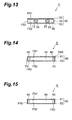
- Fig. 14 is a sectional view showing a fifth embodiment of the non-aqueous electrolyte battery as the power storage device according to the present invention.
- a non-aqueous electrolyte battery 5 shown in Fig. 14 has a constitution similar to the above described non-aqueous electrolyte battery 1 of the first embodiment shown in Fig. 3 except for the regions of the spacers 60 to be described below.
- Fig. 14 shows a sectional view of the non-aqueous electrolyte battery 5 when viewed in a direction similar to that in the sectional view of the non-aqueous electrolyte battery 1 shown in Fig. 3.
- the non-aqueous electrolyte battery 5 has a constitution similar to that of the above described non-aqueous electrolyte battery 1 of the first embodiment shown in Fig. 3 except for the following.
- the non-aqueous electrolyte battery 5 further includes metallic layers 70 arranged on the faces F60 of the spacers 60 opposite to the respective faces thereof on the side in contact with the power generation unit 40.
- the metallic layers 70 are intended to prevent penetration of moisture and/or oxygen into the sealing bag 50 from the outside thereof and dissipation of the electrolyte component within the power generation unit 40 from the inside of the sealing bag 50 to the outside thereof.
- each metallic layer 70 can use, for example, a metallic foil such as an aluminum foil, a copper foil, or a nickel foil. From the viewpoint of lightweight, excellent corrosion resistance and the like, the aluminum foil is preferably used. In the case where the metallic layer is provided on each spacer 60 which is unitized with the leads, the anode 10 and the cathode 12 are placed so as not to short-circuit via this metallic layer.
- each metallic layer 70 is not limited to the position shown in Fig. 14 as long as the position thereof enables prevention of penetration of oxygen or moisture into the power generation unit 40 from the outside thereof via the spacer 60, or dissipation of the construction component of the electrolyte in the power generation unit 40 from the power generation unit 40 to the outside thereof via the spacer 60.
- Each metallic layer 70 may be arranged within the spacer 60 or on the inner face of the spacer 60 in contact with the power generation unit 40.
- the non-aqueous electrolyte battery 5 can be also fabricated by a manufacturing method similar to that of the non-aqueous electrolyte battery 1.
- the method of attaching each metallic layer 70 to the spacer 60 there are a method of applying adhesive to the metallic layer 70 of a metallic foil or the like to adhere to the spacer 60 and a method of injection molding of the metallic layer 70 and the spacer 60 in a unitized state.
- Fig. 15 is a sectional view showing a sixth embodiment of the non-aqueous electrolyte battery as the power storage device according to the present invention.
- a non-aqueous electrolyte battery 6 shown in Fig. 15 has a constitution similar to that of the above described non-aqueous electrolyte battery 1 of the first embodiment shown in Fig. 3 except for the regions of the spacers 60 to be described below.
- Fig. 15 shows a sectional view of the non-aqueous electrolyte battery 6 when viewed in a direction similar to the sectional view of the non-aqueous electrolyte battery 1 shown in Fig. 3.
- the non-aqueous electrolyte battery 6 can be also fabricated by a manufacturing method similar to that of the non-aqueous electrolyte battery 1.
- the non-aqueous electrolyte battery 6 has a constitution similar to that of the above described non-aqueous electrolyte battery 1 of the first embodiment shown in Fig. 3 except that the faces F60 of the spacers 60 opposite to the faces on the side in contact with the power generation unit 40 are covered with the edges of the first sheet 51.
- the spacer 60 may be covered with the edges of the second sheet 52.
- each spacer 60 may be provided with a concave portion (groove) on the face thereof on the side in contact with the power generation unit 40 in the non-aqueous electrolyte battery 1 shown in Fig. 3. Accordingly, compared to the case without the concave portion (groove) provided, the sealing bag 50 can accommodate the power generation unit of a greater volume.
- the metallic layers may be provided for the non-aqueous electrolyte battery 2 of the second embodiment, the non-aqueous electrolyte battery 3 of the third embodiment, or the non-aqueous electrolyte battery 4 of the fourth embodiment.
- each metallic layer 70 is not limited, and for each of the batteries, the metallic layer 70 may be arranged in any of the face of each spacer 60 on the side in contact with the power generation unit 40, for example the inside of the spacer 60, or the face F60 of the spacer 60 opposite to the face on the side in contact with the power generation unit 40.
- a constitution may be provided for the non-aqueous electrolyte battery 2 of the second embodiment, the non-aqueous electrolyte battery 3 of the third embodiment, or the non-aqueous electrolyte battery 4 of the fourth embodiment.
- the covering style is not particularly limited.
- a constitution may be adopted, in which each spacer 60 is covered with the edge of the first sheet 51, the edge of the first sheet 51 being inserted between the spacer 60 and the second sheet 52 of the other sheet, and with the spacer 60 and the second sheet 52 not being in contact with each other.
- the spacers are still arranged between the face F51 of the first sheet 51 facing the second sheet 52 and the face F52 of the second sheet 52 facing the face F51.
- each spacer 60 opposite to the face on the side in contact with the power generation unit 40 may be covered with the edges of both the first and second sheets 51 and 52.
- the spacer in the case of fabricating the sealing bag by bending a sheet, the spacer may be disposed along the bending lines in the sheet.
- an additional spacer 60 may be arranged at the portion along the bending lines Y1-Y1 and Y2-Y2 in the non-aqueous electrolyte battery 4 shown in Figs. 11 to 13.
- the constitution of the power generation unit is not particularly limited.
- the cathode material for example, an aluminum foil having a surface subjected to an alumite treatment may be used.
- the anode material for example, an aluminum foil may be used.
- the electrolyte for example, an electrolytic solution obtained by dissolving ammonium borate in ethylene glycol may be used.
- the anode lead for example, a conductor obtained by oxidization of aluminum, such as an alumite treatment, may be used.
- a conductor of untreated aluminum may be used.
- the constitution of the power generation unit is not particularly limited.
- the anode and the cathode ones obtained by adhering a sheet fabricated by kneading activated carbon with PTFE and acetylene black to an aluminum foil as a collector may be used.
- the electrolyte an electrolytic solution obtained by adding tetraethylammonium tetrafluoroborate (Et 4 NBF 4 ) to propylene carbonate so as to have a concentration of Et 4 NBF 4 of, for example, 0.8 mol/L may be used.
- Et 4 NBF 4 tetraethylammonium tetrafluoroborate
- glass non-woven fabric or the like may be used as the separator.
- a non-aqueous electrolyte battery having a similar constitution to that of the non-aqueous electrolyte battery 1 of the first embodiment of the present invention shown in Figs. 1 to 3 was fabricated by the method previously described.
- the apparent volume of the non-aqueous electrolyte battery was 5.83 cm 3 (maximum height: 55.2 mm, maximum width: 33 mm, maximum thickness: 3.2 mm).
- the volume of the power generation unit in the sealing bag was 4.5 cm 3 .
- the volume of each spacer (width: 1.5mm, length: 50 mm, thickness: 3.0 mm) used was 0.45 cm 3 .
- the area of the sealed portion (the portion indicated by the reference symbol 51B in Fig. 1) where the first and second sheets directly contacted each other without the spacers interposed therebetween was 4.38 cm 2 .
- the power generation unit with a thickness of 3.0 mm was prepared by folding at pitch of 30 mm a laminate body where a separator (Asahi Kasei Co., trade name: Hipore, width: 50 mm, length: 300 mm, thickness: 20 ⁇ m) was arranged between an anode plate (width: 50 mm, length: 300 mm) and a cathode plate (width: 50 mm, length: 300 mm).
- a separator Asahi Kasei Co., trade name: Hipore, width: 50 mm, length: 300 mm, thickness: 20 ⁇ m
- anode plate one obtained by coating a surface of a copper foil (thickness: 20 ⁇ m) with a layer (thickness: 70 ⁇ m) of an anode activated material (graphite) was used.
- cathode plate one obtained by coating a surface of an aluminum foil (thickness: 20 ⁇ m) with a layer (thickness: 70 ⁇ m) of a cathode activated material (lithium cobaltate) was used.
- LiPF 6 was added to a solvent mixture of ethylene carbonate and diethyl carbonate in a mixture radio of ethylene carbonate to diethyl carbonate of 1/1 in a mass ratio so as to have a concentration of 1 mol/L, thus preparing a non-aqueous electrolytic solution.
- the above described laminate body of the electrodes and the separator were impregnated with 2 g of the obtained non-aqueous electrolytic solution as the non-aqueous electrolyte.
- anode lead a nickel foil (width: 3.0 mm, length: 60 mm, thickness: 0.1 ⁇ m) was used.
- cathode lead an aluminum foil (width: 3.0 mm, length: 60 mm, thickness: 0.1 ⁇ m) was used.
- acid-modified polyethylene resin film (width: 7 mm, length: 7mm, thickness: 0.1 mm) was used. Heat seal was performed in a state where each lead was arranged between two acid-modified polyethylene resin films. At this time, the two acid modified polyethylene resin films were arranged in the middle (in a longitudinal direction) of each lead. Each lead and each electrode were electrically connected by means of ultrasonic welding.
- a composite packaging material (width: 33 mm, length: 116 mm, thickness: 84 ⁇ m) composed of four layers, a PET film layer (thickness: 12 ⁇ m), an urethane adhesive layer (thickness: 2 ⁇ m), an aluminum foil layer (thickness: 20 ⁇ m), and an acid-modified polyethylene layer (thickness: 50 ⁇ m) from the outermost layer side was used.
- Two spacers were prepared by irradiating a gamma ray of 100 kGy on cuboids (width: 1.5 mm, length: 50 mm, thickness: 3.0 mm) made of high-density polyethylene resin, formed by cutting, for cross-linking of the high-density polyethylene resin.
- the joint at the sealed portion (the portion indicated by the reference symbol 51B in Fig. 1) where the first and second sheets directly contacted each other without the spacers interposed therebetween was performed by sandwiching the portion of the insulator of each lead between the first and second sheets at the sealed portion and then heat sealing.
- the output energy of this non-aqueous electrolyte battery was 1.5 W ⁇ h, where the volumetric energy density on the basis of the volume of space for the battery to be mounted was 257.3 W ⁇ h ⁇ L -1 .
- a non-aqueous electrolyte battery having a constitution similar to Example 1 was fabricated by the method previously described.
- the sealing bag thereof had a constitution similar to the sealing bag provided for the conventional non-aqueous electrolyte battery 200 shown in Figs. 20 and 21, and the non-aqueous electrolyte battery had conditions as shown below.
- the apparent volume of this non-aqueous electrolyte battery was 6.51 cm 3 (maximum height: 58 mm, maximum width 33 mm, and maximum thickness: 3.4 mm).
- the volume of the power generation unit within the sealing bag was 4.5 cm 3 .
- the total area of the sealed portion (the portion corresponding to the edge 91B in Figs. 20 and 21) where the first and second sheets directly contacted each other was 4.38 cm 3 .
- the output energy of the power generation unit of this non-aqueous electrolyte battery was 1.5 W ⁇ h, where the volumetric energy density on the basis of the volume of space for the battery to be mounted was 230.4 W ⁇ h ⁇ L -1 .
- a sealing bag having a constitution similar to the sealing bag provided for the non-aqueous electrolyte battery of Example 1 was fabricated by the method previously described, except that only the non-aqueous electrolyte used in the non-aqueous electrolyte battery of Example 1 of 2 g was enclosed inside the sealing bag.
- This sealing bag was constituted under conditions similar to Example 1 except that the metallic layers were attached to the spacers.
- this sealing bag had a constitution similar to the sealing bag of Example 2 except that the metallic layers were attached to the spacers.
- Example 1 As the metallic layers, aluminum foils (thickness: 0.1 mm, size: 3.4 mm ⁇ 58 mm) were used. In this sealing bag, only the non-aqueous electrolyte used in Example 1 of 2 g was enclosed.
- Example 2 Two samples, for each of the sealing bag shown in Example 2 and the sealing bag shown in Example 3 were prepared. Based on the "humidity cabinet test method" described in JIS K 2246-1991.5.34, these samples were placed in a RH constant temperature and humidity chamber and left in the static state for thirty days under conditions of temperature of 60°C and relative humidity of 95%. After thirty days, each sealing bag was opened and the concentration of water contained in the enclosed non-aqueous electrolyte was measured by Karl Fischer titration.
- the concentrations of water of the two samples of the sealing bag of Example 2 were 450 ppm and 520 ppm.
- the concentrations of water of the two samples of the sealing bag of Example 3 were 25 ppm and 22 ppm.
- the dead space created due to the sealed portion of the sealing bag of the power storage device in the space to be used for mounting the device in the equipment can be sufficiently reduced. Therefore, it is possible to provide a power storage device which is high in the volumetric energy density on the basis of the volume of space for the device to be mounted and capable of efficiently utilizing the space for the device to be mounted.
Landscapes
- Engineering & Computer Science (AREA)
- Power Engineering (AREA)
- Chemical & Material Sciences (AREA)
- Chemical Kinetics & Catalysis (AREA)
- Electrochemistry (AREA)
- General Chemical & Material Sciences (AREA)
- Microelectronics & Electronic Packaging (AREA)
- Sealing Battery Cases Or Jackets (AREA)
- Secondary Cells (AREA)
- Primary Cells (AREA)
- Electric Double-Layer Capacitors Or The Like (AREA)
Applications Claiming Priority (3)
| Application Number | Priority Date | Filing Date | Title |
|---|---|---|---|
| JP2001235089A JP2003045378A (ja) | 2001-08-02 | 2001-08-02 | 電力貯蔵デバイス |
| JP2001235089 | 2001-08-02 | ||
| PCT/JP2002/007812 WO2003015191A1 (fr) | 2001-08-02 | 2002-07-31 | Dispositif de stockage de poudre |
Publications (2)
| Publication Number | Publication Date |
|---|---|
| EP1414083A1 true EP1414083A1 (fr) | 2004-04-28 |
| EP1414083A4 EP1414083A4 (fr) | 2007-08-08 |
Family
ID=19066591
Family Applications (1)
| Application Number | Title | Priority Date | Filing Date |
|---|---|---|---|
| EP02755728A Withdrawn EP1414083A4 (fr) | 2001-08-02 | 2002-07-31 | Dispositif de stockage de poudre |
Country Status (7)
| Country | Link |
|---|---|
| US (1) | US20030215709A1 (fr) |
| EP (1) | EP1414083A4 (fr) |
| JP (1) | JP2003045378A (fr) |
| KR (1) | KR100491500B1 (fr) |
| CN (1) | CN1462485A (fr) |
| TW (1) | TW557595B (fr) |
| WO (1) | WO2003015191A1 (fr) |
Cited By (1)
| Publication number | Priority date | Publication date | Assignee | Title |
|---|---|---|---|---|
| CN104716386A (zh) * | 2013-12-16 | 2015-06-17 | 三星Sdi株式会社 | 柔性二次电池 |
Families Citing this family (11)
| Publication number | Priority date | Publication date | Assignee | Title |
|---|---|---|---|---|
| JP2004335889A (ja) * | 2003-05-09 | 2004-11-25 | Tdk Corp | 電気化学キャパシタ |
| CN1314148C (zh) * | 2003-10-31 | 2007-05-02 | 中信国安盟固利新能源科技有限公司 | 一种软包装锂离子电池极耳的制作方法 |
| JP5662776B2 (ja) * | 2010-12-03 | 2015-02-04 | Udトラックス株式会社 | 蓄電セル |
| KR102222118B1 (ko) * | 2014-07-14 | 2021-03-03 | 삼성에스디아이 주식회사 | 가요성 이차 전지 |
| US11108105B2 (en) * | 2015-01-22 | 2021-08-31 | Semiconductor Energy Laboratory Co., Ltd. | Secondary battery and electronic device |
| CN208045659U (zh) * | 2016-12-06 | 2018-11-02 | Sk新技术株式会社 | 二次电池模块 |
| US20190020000A1 (en) * | 2017-07-11 | 2019-01-17 | Apple Inc. | Battery cell tabs with a unitary seal |
| JP3212865U (ja) | 2017-07-25 | 2017-10-05 | 住友電気工業株式会社 | 電池およびスペーサ |
| JP6537198B2 (ja) * | 2017-08-28 | 2019-07-03 | 藤森工業株式会社 | 電池容器、及びフィルム包装電池 |
| JP2024017790A (ja) * | 2022-07-28 | 2024-02-08 | 株式会社Aescジャパン | 電池セル |
| CN116800129B (zh) * | 2023-06-26 | 2024-03-15 | 北京能通未来节能科技有限公司 | 一种节约电力电能装置 |
Family Cites Families (11)
| Publication number | Priority date | Publication date | Assignee | Title |
|---|---|---|---|---|
| JPS62217563A (ja) * | 1986-03-19 | 1987-09-25 | Shin Kobe Electric Mach Co Ltd | 密閉形鉛蓄電池 |
| JPS63284752A (ja) * | 1987-05-15 | 1988-11-22 | Yuasa Battery Co Ltd | 密閉形鉛蓄電池 |
| JP3137061B2 (ja) * | 1997-04-22 | 2001-02-19 | 住友電気工業株式会社 | 非水電解質電池 |
| US5989751A (en) * | 1997-06-16 | 1999-11-23 | International Business Machines Corporation | High energy density, flexible lithium primary batteries |
| US6245456B1 (en) * | 1998-01-13 | 2001-06-12 | Sumitomo Electric Industries, Ltd. | Non-aqueous electrolyte battery using a sealing bag comprising heat laminated layers |
| JPH11162421A (ja) * | 1997-11-26 | 1999-06-18 | Toshiba Battery Co Ltd | シート形電池 |
| JPH11260406A (ja) * | 1998-03-12 | 1999-09-24 | Toshiba Battery Co Ltd | 高分子電解質リチウム二次電池 |
| JP2000173559A (ja) * | 1998-12-03 | 2000-06-23 | Tokai Rubber Ind Ltd | 薄型電池用袋体 |
| JP2000182579A (ja) * | 1998-12-16 | 2000-06-30 | Toshiba Battery Co Ltd | 板状ポリマー電解質電池 |
| CN1180506C (zh) * | 1999-03-26 | 2004-12-15 | 松下电器产业株式会社 | 叠合片封装型电池 |
| JP2001093496A (ja) * | 1999-07-19 | 2001-04-06 | Toshiba Battery Co Ltd | 扁平電池の収容ケース及びそれを用いた電池パック |
-
2001
- 2001-08-02 JP JP2001235089A patent/JP2003045378A/ja active Pending
-
2002
- 2002-07-31 EP EP02755728A patent/EP1414083A4/fr not_active Withdrawn
- 2002-07-31 WO PCT/JP2002/007812 patent/WO2003015191A1/fr not_active Ceased
- 2002-07-31 CN CN02801472A patent/CN1462485A/zh active Pending
- 2002-07-31 KR KR10-2002-7017105A patent/KR100491500B1/ko not_active Expired - Fee Related
- 2002-08-01 TW TW091117335A patent/TW557595B/zh not_active IP Right Cessation
-
2003
- 2003-04-02 US US10/404,052 patent/US20030215709A1/en not_active Abandoned
Cited By (3)
| Publication number | Priority date | Publication date | Assignee | Title |
|---|---|---|---|---|
| CN104716386A (zh) * | 2013-12-16 | 2015-06-17 | 三星Sdi株式会社 | 柔性二次电池 |
| EP2884560A1 (fr) * | 2013-12-16 | 2015-06-17 | Samsung SDI Co., Ltd. | Batterie secondaire flexible |
| US9941492B2 (en) | 2013-12-16 | 2018-04-10 | Samsung Sdi Co., Ltd. | Flexible secondary battery having a bonding portion extending in a lengthwise direction |
Also Published As
| Publication number | Publication date |
|---|---|
| EP1414083A4 (fr) | 2007-08-08 |
| TW557595B (en) | 2003-10-11 |
| KR20030045681A (ko) | 2003-06-11 |
| CN1462485A (zh) | 2003-12-17 |
| KR100491500B1 (ko) | 2005-05-30 |
| US20030215709A1 (en) | 2003-11-20 |
| WO2003015191A9 (fr) | 2004-07-15 |
| JP2003045378A (ja) | 2003-02-14 |
| WO2003015191A1 (fr) | 2003-02-20 |
Similar Documents
| Publication | Publication Date | Title |
|---|---|---|
| EP3709392B1 (fr) | Batterie secondaire | |
| JP4628682B2 (ja) | 電池部ユニット及びこれを採用したリチウム2次電池 | |
| KR100449757B1 (ko) | 전지부와 이를 채용한 이차전지 | |
| KR100496305B1 (ko) | 파우치형 리튬 이차 전지와 이의 제조 방법 | |
| KR101499471B1 (ko) | 이차전지의 제조방법 및 이를 이용하여 생산되는 이차전지 | |
| US7833657B2 (en) | External case for secondary batteries and secondary battery using the external case | |
| US7556885B2 (en) | Battery pack | |
| US20020127362A1 (en) | Flexible laminates and housings for batteries | |
| EP1734596A1 (fr) | Dispostiif electrique enrobe en couche mince et organe de couverutre collecteur pour le dispositif electrique enrobe en couche mince: | |
| JP2002352863A (ja) | リチウム二次単電池およびリチウム二次単電池の接続構造体 | |
| US10811730B2 (en) | Pouch exterior for secondary battery and pouch-type secondary battery comprising same | |
| EP1414083A1 (fr) | Dispositif de stockage de poudre | |
| KR100922742B1 (ko) | 파우치형 케이스와, 이를 적용한 리튬 이차 전지 | |
| JP2005018990A (ja) | 積層型リチウムイオン二次電池 | |
| KR101111074B1 (ko) | 구조적 안정성과 절연저항성이 우수한 전지셀 | |
| KR102540149B1 (ko) | 이차 전지 | |
| JP3632062B2 (ja) | 薄型ポリマー電池 | |
| JP2000048773A (ja) | 非水電解質電池 | |
| JP4237557B2 (ja) | 電池パック | |
| EP4250468A1 (fr) | Batterie secondaire | |
| JP2004319098A (ja) | 電気化学セル及びその製造方法 | |
| JP3601283B2 (ja) | 非水電解質電池 | |
| KR101792578B1 (ko) | 변형된 형태의 리드 필름을 포함하는 전지셀 | |
| KR100670438B1 (ko) | 파우치형 리튬 이차 전지 | |
| KR100551395B1 (ko) | 파우치형 리튬 이차 전지 제조 방법 |
Legal Events
| Date | Code | Title | Description |
|---|---|---|---|
| PUAI | Public reference made under article 153(3) epc to a published international application that has entered the european phase |
Free format text: ORIGINAL CODE: 0009012 |
|
| 17P | Request for examination filed |
Effective date: 20030501 |
|
| AK | Designated contracting states |
Kind code of ref document: A1 Designated state(s): AT BE BG CH CY CZ DE DK EE ES FI FR GB GR IE IT LI LU MC NL PT SE SK TR |
|
| A4 | Supplementary search report drawn up and despatched |
Effective date: 20070705 |
|
| RIC1 | Information provided on ipc code assigned before grant |
Ipc: H01M 2/08 20060101ALN20070629BHEP Ipc: H01M 2/02 20060101AFI20030226BHEP Ipc: H01M 10/40 20060101ALN20070629BHEP Ipc: H01M 2/06 20060101ALN20070629BHEP Ipc: H01G 9/08 20060101ALI20070629BHEP Ipc: H01G 9/10 20060101ALN20070629BHEP |
|
| STAA | Information on the status of an ep patent application or granted ep patent |
Free format text: STATUS: THE APPLICATION HAS BEEN WITHDRAWN |
|
| 18W | Application withdrawn |
Effective date: 20071001 |