EP1414130A2 - Moteur électrique avec rotor à aimants permanents - Google Patents
Moteur électrique avec rotor à aimants permanents Download PDFInfo
- Publication number
- EP1414130A2 EP1414130A2 EP03007579A EP03007579A EP1414130A2 EP 1414130 A2 EP1414130 A2 EP 1414130A2 EP 03007579 A EP03007579 A EP 03007579A EP 03007579 A EP03007579 A EP 03007579A EP 1414130 A2 EP1414130 A2 EP 1414130A2
- Authority
- EP
- European Patent Office
- Prior art keywords
- permanent magnet
- motor
- rotor
- rotary shaft
- magnet insertion
- Prior art date
- Legal status (The legal status is an assumption and is not a legal conclusion. Google has not performed a legal analysis and makes no representation as to the accuracy of the status listed.)
- Granted
Links
Images



Classifications
-
- H—ELECTRICITY
- H02—GENERATION; CONVERSION OR DISTRIBUTION OF ELECTRIC POWER
- H02K—DYNAMO-ELECTRIC MACHINES
- H02K1/00—Details of the magnetic circuit
- H02K1/06—Details of the magnetic circuit characterised by the shape, form or construction
- H02K1/22—Rotating parts of the magnetic circuit
- H02K1/27—Rotor cores with permanent magnets
-
- H—ELECTRICITY
- H02—GENERATION; CONVERSION OR DISTRIBUTION OF ELECTRIC POWER
- H02K—DYNAMO-ELECTRIC MACHINES
- H02K1/00—Details of the magnetic circuit
- H02K1/06—Details of the magnetic circuit characterised by the shape, form or construction
- H02K1/22—Rotating parts of the magnetic circuit
- H02K1/27—Rotor cores with permanent magnets
- H02K1/2706—Inner rotors
- H02K1/272—Inner rotors the magnetisation axis of the magnets being perpendicular to the rotor axis
- H02K1/274—Inner rotors the magnetisation axis of the magnets being perpendicular to the rotor axis the rotor consisting of two or more circumferentially positioned magnets
- H02K1/2753—Inner rotors the magnetisation axis of the magnets being perpendicular to the rotor axis the rotor consisting of two or more circumferentially positioned magnets the rotor consisting of magnets or groups of magnets arranged with alternating polarity
- H02K1/276—Magnets embedded in the magnetic core, e.g. interior permanent magnets [IPM]
- H02K1/2766—Magnets embedded in the magnetic core, e.g. interior permanent magnets [IPM] having a flux concentration effect
-
- H—ELECTRICITY
- H02—GENERATION; CONVERSION OR DISTRIBUTION OF ELECTRIC POWER
- H02K—DYNAMO-ELECTRIC MACHINES
- H02K29/00—Motors or generators having non-mechanical commutating devices, e.g. discharge tubes or semiconductor devices
Definitions
- the present invention relates to an electric motor, and particularly, to a rotor structure of an electric motor.
- a brushless direct current (BLDC) motor is made by removing a brush and a commutator from a direct current motor and by installing an electric rectifying device not to generate mechanical and electrical noise. Therefore, motor having various speed from low to high can be fabricated, and a motor having stable rotation torque and long life span with multiple poles can be made.
- BLDC brushless direct current
- Figure 1 is a longitudinal cross-sectional view showing a conventional BLDC motor
- Figure 2 is a cross-sectional view showing in line II-II
- Figure 3 is a brief view showing distribution of magnetic flux density of the motor shown in Figure 1.
- the conventional BLDC motor includes a housing body 11 having inner space; a housing 10 having a cover portion 12 for covering an opening portion of the housing body 11 and bearings 13 and 14 installed on center portions thereof; a stator 20 fixedly installed in the housing 10; a rotor 30 rotatably inserted into the stator 20; and a rotary shaft 40 fixedly pressed into the rotor 30 and rotatably inserted into the respective bearings 13, 14 in order to transmit the rotation force of the rotor 30 to outer part.
- the stator 20 includes a stator core 26 including a plurality of teeth 21 protrudingly formed on an inner circumferential surface thereof, slots 22 formed between the respective teeth 21, and slot opening portions 23 formed between tips 25 which are protrudingly formed on ends of the teeth 21; and a coil 24 wound on the teeth 21 of the stator core 26.
- the rotor 30 includes a shaft insertion hole 31, through which the rotary shaft 40 is fixedly press-fitted, on a center portion thereof.
- rotor cores 36 on which four magnet insertion slots 32 of 'V' shape for fixing two permanent magnets which are symmetric for magnetic center respectively are formed as centering around the rotary shaft 40 in a radial direction are laminated and coupled by a rivet through the rivet hole 35 so that two magnetic centers cross each other in right angle on outer side of the shaft insertion hole 31.
- the permanent magnets 33 are inserted into ends of the magnet insertion slots 32 in pairs to have equal polarity, and installed to have polarity opposite to that of another permanent magnet 33 inserted into adjacent magnet insertion slot 32.
- a recess 34 is formed around the end of the magnet insertion slot 32 in radial direction in order to disperse the magnetic flux density of the permanent magnet 33.
- the polarity of the teeth 31 can be changed by the electric source flowing on the coil 24 which is wound on the stator core 26, and according to the changes, the repulsive force or the attractive force is applied with the adjacent permanent magnets 33. In addition, when the repulsive or attractive force is applied toward the tangent direction of the rotor core 36, the rotor 30 can be rotated smoothly.
- shock force in radial direction generated due to the magnetic flux increase on the tip 25 of the tooth 21 generates vibration when the rotor 30 is rotated, and accordingly, noise due to the vibration is also generated.
- an object of the present invention is to provide an electric motor having less vibration and noise by restricting generation of shock force generated around a rotor and teeth of a stator.
- an electric motor comprising: a stator including a plurality of teeth and a coil unit wound on the teeth to form rotating magnetic flux by applied electric source; a rotary shaft; and a rotor rotatably installed in the stator, the rotor including a shaft insertion hole so that the rotary shaft can be inserted therethrough and fixed, wherein the rotor includes a plurality of permanent magnet insertion slots of 'V' shape formed as centering around the shaft insertion hole in radial direction, and permanent magnets are inserted and fixed into the permanent magnet insertion slots respectively, and a plurality of air gap expanding portions, on which air gaps from the teeth of the stator are expanded, are formed on an outer circumferential surface of the rotor.
- Figure 4 is a cross-sectional view showing an electric motor according to the present invention
- Figure 5 is a geometrical view showing a core of a rotor in the electric motor shown in Figure 4
- Figure 6 is an enlarged view showing A part of Figure 5.
- an electric motor includes: a stator 20 including a plurality of teeth 21 and coils 24 wound on the teeth 21 to form rotating magnetic flux by applied electric source; a rotary shaft 400; and a rotor 300, which is rotatably installed in the stator 20, including a shaft insertion hole 310 so that the rotary shaft 400 can be inserted and fixed therein.
- the electric motor of the present invention includes a housing 10, on which the stator 20 is fixedly installed, having a rotary shaft supporting portion in which the rotary shaft 400 is rotatably fitted.
- the housing 10 includes an opening portion on one side thereof, and includes a cover portion 12 covering the opening portion and including a rotary shaft supporting portion through which one side of the rotary shaft 400 is rotatably fitted.
- the rotary shaft supporting portion can be embodied in various types, however, bearings 13 and 14 are usually used as the rotary shaft supporting portion.
- the rotary shaft 400 transmits rotational force generated by an interaction between the stator 20 and the rotor 300 to outer side.
- the electric motor according to the present invention is generally a BLDC motor, and the coil 24 is wound on the teeth 21 of the stator 20 in a concentrated winding method.
- the rotor 300 includes a plurality of permanent magnet insertion slots 320 formed in a radial direction of the rotary shaft 400 centering around the shaft insertion hole 310, and permanent magnets 330 are inserted and fixed in the permanent magnet insertion slots 320 respectively.
- a plurality of air gap expanding portions 500 are formed on an outer circumferential surface of the rotor 300.
- the stator 20 comprises: a stator core 26 including a plurality of teeth 21 protrudingly formed on an inner circumferential surface thereof, slots 22 formed between the respective teeth 21, and a slot opening portion 23 formed between tips 25 which are protrudingly formed from both sides of the ends of the teeth 21; and coil 24 intensively (concentratedly) wound on the teeth 21 of the stator core 26.
- the rotor 300 is made by laminating rotor cores 360 which include respectively: a shaft insertion hole 310 for press-fitting and fixing the rotary shaft 400 formed on a center portion thereof; and four permanent magnet insertion slots 330 of 'V' or 'U' shape, in which permanent magnets 320 are inserted is formed on outer side of the shaft insertion hole 310 in a circumferential direction of the rotary shaft 400, and are respectively symmetrical for two center lines of magnetic poles (x-x, y-y) which cross each other in right angles.
- the rotor cores 360 are fixedly coupled by a rivet, etc. through a rivet hole 350.
- the permanent magnets 330 are in pairs, and the pairs of permanent magnets are respectively inserted into the permanent magnet insertion slots 320, and the ends of each pair of permanent magnets in the ends of each slot 320 have same polar directions (N or S) and polar directions opposite to those of the adjacent pair of permanent magnet 330 inserted into slot 320 adjacent thereto.
- the permanent magnet insertion slots 320 are disposed in a radial direction centering around the rotary shaft 400, and especially, the slots are formed to be symmetrical for each other centering around an extended line in the radial direction of the rotary shaft 400 (x or y) from the rotary shaft 400.
- recesses 340 are formed around the ends of each permanent magnet insertion slot 320 in a radial direction in order to disperse the magnetic flux density of the permanent magnet 330.
- the air gap expanding portions 500 are formed on the outer circumferential surface of the core located between the both ends of each permanent magnet insertion slot 320 to be closer to the end of the slot located on rotational direction of the rotor 300 (clockwise direction in Figure 5).
- the air gap expanding portions 500 are formed by cutting some part of the rotor 300, that is, the circumferential surface of the rotor core 360 as straight line shape.
- the air gap expanding portions 500 are respectively formed near the permanent magnet 330b, which is located on the rotational direction, between the two permanent magnets 330a and 330b constructing the permanent magnet 330, and more desirably, the air gap expanding portions 500 are located on a half side 360b on the rotational direction of the rotary shaft 400 when the circumferential surface of the rotor 300 between the both ends of the magnet member insertion slot 320 is divided into halves 360a and 360b.
- the respective teeth 21 When the electric source is applied sequentially to the coil wound on the respective teeth 21 of the stator 20 by an electric source applying circuit (not shown), the respective teeth 21 have polarities of N and S poles alternatively. And accordingly, the rotor 300 is rotated by the magnetic flux between the teeth 21 of the stator 20 and the permanent magnet 330 of the rotor 300 adjacent to the teeth 21.
- the magnetic flux of the permanent magnet 330 is generated actively, and therefore, the magnetic flux density is concentrated on a tip 25 of the teeth 21.
- the air gap expanding portion 500 which expands the air gap by cutting some of the outer circumferential surface of the rotor 300 corresponding to the tip 25 of the teeth 21 is formed to reduce the shock force of the rotor 300 toward the radial direction due to the generation of peak flux.
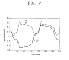
- Figure 7 is a graph comparing distributions of magnetic flux density on the electric motor of the present invention and the conventional electric motor.
- the peak flux is reduced and wavelength is similar to the sine wave in the magnetic flux density 2 of the present invention around the air gap of the teeth 21 of the stator 20 according to the rotating angle of the rotor 300 when comparing them to the magnetic flux density 1 of the conventional electric motor.
Landscapes
- Engineering & Computer Science (AREA)
- Power Engineering (AREA)
- Permanent Field Magnets Of Synchronous Machinery (AREA)
- Iron Core Of Rotating Electric Machines (AREA)
- Brushless Motors (AREA)
Applications Claiming Priority (2)
| Application Number | Priority Date | Filing Date | Title |
|---|---|---|---|
| KR2002065690 | 2002-10-26 | ||
| KR10-2002-0065690A KR100486589B1 (ko) | 2002-10-26 | 2002-10-26 | 브러쉬리스 직류 모터의 회전자 구조 |
Publications (3)
| Publication Number | Publication Date |
|---|---|
| EP1414130A2 true EP1414130A2 (fr) | 2004-04-28 |
| EP1414130A3 EP1414130A3 (fr) | 2005-02-16 |
| EP1414130B1 EP1414130B1 (fr) | 2006-11-22 |
Family
ID=32064981
Family Applications (1)
| Application Number | Title | Priority Date | Filing Date |
|---|---|---|---|
| EP03007579A Expired - Lifetime EP1414130B1 (fr) | 2002-10-26 | 2003-04-02 | Moteur électrique avec rotor à aimants permanents |
Country Status (6)
| Country | Link |
|---|---|
| US (1) | US6774523B2 (fr) |
| EP (1) | EP1414130B1 (fr) |
| JP (1) | JP3793170B2 (fr) |
| KR (1) | KR100486589B1 (fr) |
| CN (1) | CN100541987C (fr) |
| DE (1) | DE60309811T2 (fr) |
Cited By (4)
| Publication number | Priority date | Publication date | Assignee | Title |
|---|---|---|---|---|
| WO2009143855A1 (fr) * | 2008-05-29 | 2009-12-03 | Открытое Акционерное Общество "Инжиниринговая Нефтегазовая Компания - Всероссийский Научно-Исследовательский Институт По Строительству И Эксплуатации Трубопроводов, Объектов Тэк" | Machine électrique sans balais à excitation réglable |
| EP2038984A4 (fr) * | 2006-06-12 | 2012-07-25 | Remy Int Inc | Machine électrique à aimants permanents internes |
| WO2013124787A1 (fr) | 2012-02-20 | 2013-08-29 | Moteurs Leroy-Somer | Rotor de machine tournante a concentration de flux |
| CN106716782A (zh) * | 2014-09-26 | 2017-05-24 | 松下知识产权经营株式会社 | 感应电动机 |
Families Citing this family (39)
| Publication number | Priority date | Publication date | Assignee | Title |
|---|---|---|---|---|
| DE10316831A1 (de) * | 2002-04-15 | 2003-11-27 | Denso Corp | Permanentmagnetrotor für eine rotierende elektrische Maschine mit Innenrotor und magnetsparender Rotor für einen Synchronmotor |
| JP4449035B2 (ja) * | 2004-03-10 | 2010-04-14 | 日立オートモティブシステムズ株式会社 | 電動車両用の永久磁石回転電機 |
| US20060022541A1 (en) * | 2004-07-30 | 2006-02-02 | Raymond Ong | Rotor hub and assembly for a permanent magnet power electric machine |
| EP1670121B2 (fr) * | 2004-11-22 | 2012-04-04 | MINEBEA Co., Ltd. | Machine électrique, moteur à courant continu sans balais en particulier |
| RU2316103C2 (ru) * | 2005-07-14 | 2008-01-27 | "Центр Разработки Нефтедобывающего Оборудования" ("Црно") | Магнитная система ротора |
| JP2007074870A (ja) * | 2005-09-09 | 2007-03-22 | Toyota Motor Corp | 永久磁石埋込型ロータおよび永久磁石埋込型モータ |
| US7385328B2 (en) | 2006-05-23 | 2008-06-10 | Reliance Electric Technologies, Llc | Cogging reduction in permanent magnet machines |
| FI119457B (fi) * | 2006-08-31 | 2008-11-14 | Abb Oy | Kestomagnetoidun sähkökoneen roottori |
| JP2008206358A (ja) * | 2007-02-22 | 2008-09-04 | Daikin Ind Ltd | モータおよび圧縮機 |
| US7932658B2 (en) * | 2007-03-15 | 2011-04-26 | A.O. Smith Corporation | Interior permanent magnet motor including rotor with flux barriers |
| US20090224624A1 (en) * | 2008-03-06 | 2009-09-10 | Ajith Kuttannair Kumar | Rotor structure for interior permanent magnet electromotive machine |
| JP5526495B2 (ja) * | 2008-05-21 | 2014-06-18 | 富士電機株式会社 | 永久磁石式回転電機 |
| CN101594011A (zh) * | 2008-05-30 | 2009-12-02 | 德昌电机(深圳)有限公司 | 永磁无刷电机及其转子 |
| US20100117475A1 (en) | 2008-11-11 | 2010-05-13 | Ford Global Technologies, Llc | Permanent Magnet Machine with Offset Pole Spacing |
| US8536748B2 (en) | 2008-11-11 | 2013-09-17 | Ford Global Technologies, Llc | Permanent magnet machine with different pole arc angles |
| KR101578424B1 (ko) * | 2009-02-05 | 2015-12-17 | 엘지전자 주식회사 | 영구자석 삽입식 비엘디시 모터 및 이를 구비한 압축기 |
| CN101944809B (zh) * | 2009-07-09 | 2012-09-05 | 山东中际电工装备股份有限公司 | 扩涨板扩张机构 |
| EP2580850B1 (fr) | 2010-06-14 | 2021-11-10 | Black & Decker, Inc. | Unité de commande pour moteur sans balais dans un outil électrique |
| EP2600499B1 (fr) | 2010-07-28 | 2018-12-12 | Nissan Motor Co., Ltd | Rotor pour machine électrique rotative |
| EP2557661B1 (fr) * | 2011-08-10 | 2020-03-11 | LG Innotek Co., Ltd. | Noyau de rotor de moteur |
| JP2014045634A (ja) * | 2012-08-29 | 2014-03-13 | Toyota Motor Corp | ロータ及びこのロータを備える回転電機 |
| JP5906360B2 (ja) * | 2013-08-09 | 2016-04-20 | 株式会社 成田 | 磁力回転装置、電動機、および電動発電機 |
| JP2015122936A (ja) | 2013-10-31 | 2015-07-02 | 三星電子株式会社Samsung Electronics Co.,Ltd. | 埋込磁石型モータ及び埋込磁石型モータの使用方法 |
| US10205359B2 (en) | 2013-11-18 | 2019-02-12 | Steering Solutions Ip Holding Corporation | Low cost permanent magnet motor for an electric power steering system |
| US9979243B2 (en) * | 2014-11-18 | 2018-05-22 | Steering Solutions Ip Holding Corporation | Low cost injection molded buried permanent magnet motor for an electric power steering system |
| US10523081B2 (en) | 2014-11-25 | 2019-12-31 | Black & Decker Inc. | Brushless motor for a power tool |
| CN106300730B (zh) * | 2015-06-08 | 2019-01-01 | 珠海格力节能环保制冷技术研究中心有限公司 | 电机转子及具有其的电机 |
| US10786894B2 (en) | 2015-10-14 | 2020-09-29 | Black & Decker Inc. | Brushless motor system for power tools |
| CN106059235A (zh) * | 2016-07-22 | 2016-10-26 | 佛山市奥力博动力工程有限公司 | 一种新型发电机磁钢装置 |
| JP2018182968A (ja) | 2017-04-19 | 2018-11-15 | ファナック株式会社 | ロータおよび回転電機 |
| TWM576750U (zh) | 2017-07-25 | 2019-04-11 | 美商米沃奇電子工具公司 | 電氣組合物、電動化裝置系統、電池組、電馬達、馬達總成及電馬達總成 |
| CN107482809A (zh) * | 2017-09-19 | 2017-12-15 | 安徽沃弗电力科技有限公司 | 一种磁力耦合器的永磁体转子 |
| US10886801B2 (en) | 2017-09-29 | 2021-01-05 | Wisconsin Alumni Research Foundation | Vernier machine with shaped permanent magnet groups |
| JP6606157B2 (ja) * | 2017-11-15 | 2019-11-13 | ファナック株式会社 | ロータおよび回転電機 |
| CN111903038B (zh) * | 2018-04-10 | 2023-11-28 | 三菱电机株式会社 | 电动机、压缩机及空气调节装置 |
| EP3917708A4 (fr) | 2019-02-18 | 2022-11-30 | Milwaukee Electric Tool Corporation | Outil à percussion |
| CN109742876A (zh) * | 2019-03-05 | 2019-05-10 | 欣盛尚驰科技股份有限公司 | 一种六相开关磁阻电机驱动系统 |
| CN110994838A (zh) * | 2019-12-16 | 2020-04-10 | 珠海格力电器股份有限公司 | 转子组件和交替极电机 |
| CN212486356U (zh) * | 2020-02-28 | 2021-02-05 | 丹佛斯(天津)有限公司 | 转子、内置式永磁电机以及压缩机 |
Family Cites Families (16)
| Publication number | Priority date | Publication date | Assignee | Title |
|---|---|---|---|---|
| DE1488733A1 (de) * | 1965-12-08 | 1969-06-19 | Siemens Ag | Permanenterregte elektrische Maschine mit Dauermagnetbloecken im Laeufer |
| US4806717A (en) * | 1979-09-21 | 1989-02-21 | General Electric Company | Drive for a laundry machine |
| JPH01159570U (fr) * | 1988-04-19 | 1989-11-06 | ||
| KR100302103B1 (ko) * | 1992-07-09 | 2001-10-22 | 구사마 사부로 | 무브러시모우터 |
| JP2748694B2 (ja) * | 1992-08-12 | 1998-05-13 | セイコーエプソン株式会社 | ブラシレスモータの永久磁石回転子及びその製造方法 |
| JPH07222384A (ja) * | 1994-01-27 | 1995-08-18 | Toshiba Corp | 永久磁石形モータ |
| EP0823771B1 (fr) * | 1996-02-23 | 2006-04-26 | Matsushita Electric Industrial Co., Ltd. | Moteur |
| KR19980015497A (ko) * | 1996-08-22 | 1998-05-25 | 구자홍 | 매입형 영구자석 동기전동기의 회전자 구조 |
| JPH10285847A (ja) * | 1997-04-09 | 1998-10-23 | Mitsubishi Electric Corp | 永久磁石形モータ |
| TW364234B (en) * | 1997-04-14 | 1999-07-11 | Sanyo Electric Co | Rotor for an electric motor |
| BR9705579A (pt) * | 1997-09-26 | 1999-05-11 | Brasil Compressores Sa | Rotor de motor elétrico e método de produção de rotor de motor elétrico |
| JP3301981B2 (ja) * | 1998-12-18 | 2002-07-15 | 三洋電機株式会社 | 集中巻方式のブラシレスdcモータ |
| DE19915664A1 (de) * | 1999-04-07 | 2000-10-19 | Siemens Ag | Elektrische Maschine mit einem Stator |
| JP2001069701A (ja) * | 1999-08-30 | 2001-03-16 | Mitsubishi Heavy Ind Ltd | 磁石モータ |
| JP2001342954A (ja) * | 2000-05-31 | 2001-12-14 | Sanyo Electric Co Ltd | 電動圧縮機及びそれを用いた冷却装置 |
| JP3787756B2 (ja) * | 2000-08-29 | 2006-06-21 | 株式会社日立製作所 | 永久磁石式回転電機 |
-
2002
- 2002-10-26 KR KR10-2002-0065690A patent/KR100486589B1/ko not_active Expired - Lifetime
-
2003
- 2003-04-02 DE DE60309811T patent/DE60309811T2/de not_active Expired - Lifetime
- 2003-04-02 EP EP03007579A patent/EP1414130B1/fr not_active Expired - Lifetime
- 2003-04-14 US US10/412,341 patent/US6774523B2/en not_active Expired - Lifetime
- 2003-04-17 JP JP2003113242A patent/JP3793170B2/ja not_active Expired - Fee Related
- 2003-04-25 CN CNB03122198XA patent/CN100541987C/zh not_active Expired - Fee Related
Cited By (4)
| Publication number | Priority date | Publication date | Assignee | Title |
|---|---|---|---|---|
| EP2038984A4 (fr) * | 2006-06-12 | 2012-07-25 | Remy Int Inc | Machine électrique à aimants permanents internes |
| WO2009143855A1 (fr) * | 2008-05-29 | 2009-12-03 | Открытое Акционерное Общество "Инжиниринговая Нефтегазовая Компания - Всероссийский Научно-Исследовательский Институт По Строительству И Эксплуатации Трубопроводов, Объектов Тэк" | Machine électrique sans balais à excitation réglable |
| WO2013124787A1 (fr) | 2012-02-20 | 2013-08-29 | Moteurs Leroy-Somer | Rotor de machine tournante a concentration de flux |
| CN106716782A (zh) * | 2014-09-26 | 2017-05-24 | 松下知识产权经营株式会社 | 感应电动机 |
Also Published As
| Publication number | Publication date |
|---|---|
| JP3793170B2 (ja) | 2006-07-05 |
| US6774523B2 (en) | 2004-08-10 |
| KR100486589B1 (ko) | 2005-05-03 |
| EP1414130B1 (fr) | 2006-11-22 |
| CN100541987C (zh) | 2009-09-16 |
| DE60309811D1 (de) | 2007-01-04 |
| KR20040036485A (ko) | 2004-04-30 |
| EP1414130A3 (fr) | 2005-02-16 |
| US20040080228A1 (en) | 2004-04-29 |
| DE60309811T2 (de) | 2007-09-13 |
| CN1492566A (zh) | 2004-04-28 |
| JP2004147487A (ja) | 2004-05-20 |
Similar Documents
| Publication | Publication Date | Title |
|---|---|---|
| EP1414130B1 (fr) | Moteur électrique avec rotor à aimants permanents | |
| US9018816B2 (en) | Rotor of motor having interpole magnets in holding member | |
| EP1734638A1 (fr) | Moteur à aimants permanents | |
| JPH10322948A (ja) | 永久磁石埋込形回転子 | |
| JP3950114B2 (ja) | 誘導電動機の固定子 | |
| JP2013059178A (ja) | 磁気ギア | |
| CN110912297A (zh) | 电机和压缩机 | |
| KR100645585B1 (ko) | 직류 모터 | |
| JP2005020914A (ja) | 電動機及びヨークハウジング | |
| KR101405973B1 (ko) | 모터 | |
| KR20200014040A (ko) | 토크리플 감소를 위한 노치구조의 전동기 | |
| KR20190074467A (ko) | 분할 고정자를 갖는 모터 | |
| JP2018117513A (ja) | 電気モータ及びその磁気コア | |
| KR100511272B1 (ko) | 브러쉬리스 직류 모터의 회전자 구조 | |
| KR101448647B1 (ko) | 모터 | |
| KR101448649B1 (ko) | 모터 | |
| KR101448646B1 (ko) | 모터 | |
| WO2021229954A1 (fr) | Rotor et moteur électrique | |
| KR102872324B1 (ko) | 자속 집중형 회전자 및 회전자의 착자 장치 | |
| KR20100005890A (ko) | 모터 | |
| KR20000001924A (ko) | 전기모터 | |
| KR100277576B1 (ko) | 전기모터 | |
| KR200413099Y1 (ko) | 모터 고정자용 인슐레이터 | |
| KR20200102590A (ko) | 외전형 bldc 모터 | |
| JP3707027B2 (ja) | マイクロ扁平振動モータの最適化構造 |
Legal Events
| Date | Code | Title | Description |
|---|---|---|---|
| PUAI | Public reference made under article 153(3) epc to a published international application that has entered the european phase |
Free format text: ORIGINAL CODE: 0009012 |
|
| AK | Designated contracting states |
Kind code of ref document: A2 Designated state(s): AT BE BG CH CY CZ DE DK EE ES FI FR GB GR HU IE IT LI LU MC NL PT SE SI SK TR |
|
| AX | Request for extension of the european patent |
Extension state: AL LT LV MK RO |
|
| PUAL | Search report despatched |
Free format text: ORIGINAL CODE: 0009013 |
|
| AK | Designated contracting states |
Kind code of ref document: A3 Designated state(s): AT BE BG CH CY CZ DE DK EE ES FI FR GB GR HU IE IT LI LU MC NL PT SE SI SK TR |
|
| AX | Request for extension of the european patent |
Extension state: AL LT LV MK RO |
|
| RIC1 | Information provided on ipc code assigned before grant |
Ipc: 7H 02K 1/27 A Ipc: 7H 02K 29/03 B |
|
| 17P | Request for examination filed |
Effective date: 20050408 |
|
| AKX | Designation fees paid |
Designated state(s): DE FR GB |
|
| GRAP | Despatch of communication of intention to grant a patent |
Free format text: ORIGINAL CODE: EPIDOSNIGR1 |
|
| GRAS | Grant fee paid |
Free format text: ORIGINAL CODE: EPIDOSNIGR3 |
|
| GRAA | (expected) grant |
Free format text: ORIGINAL CODE: 0009210 |
|
| AK | Designated contracting states |
Kind code of ref document: B1 Designated state(s): DE FR GB |
|
| REG | Reference to a national code |
Ref country code: GB Ref legal event code: FG4D |
|
| REF | Corresponds to: |
Ref document number: 60309811 Country of ref document: DE Date of ref document: 20070104 Kind code of ref document: P |
|
| ET | Fr: translation filed | ||
| PLBE | No opposition filed within time limit |
Free format text: ORIGINAL CODE: 0009261 |
|
| STAA | Information on the status of an ep patent application or granted ep patent |
Free format text: STATUS: NO OPPOSITION FILED WITHIN TIME LIMIT |
|
| 26N | No opposition filed |
Effective date: 20070823 |
|
| REG | Reference to a national code |
Ref country code: FR Ref legal event code: PLFP Year of fee payment: 14 |
|
| REG | Reference to a national code |
Ref country code: FR Ref legal event code: PLFP Year of fee payment: 15 |
|
| REG | Reference to a national code |
Ref country code: FR Ref legal event code: PLFP Year of fee payment: 16 |
|
| PGFP | Annual fee paid to national office [announced via postgrant information from national office to epo] |
Ref country code: GB Payment date: 20180306 Year of fee payment: 16 |
|
| PGFP | Annual fee paid to national office [announced via postgrant information from national office to epo] |
Ref country code: FR Payment date: 20180308 Year of fee payment: 16 |
|
| GBPC | Gb: european patent ceased through non-payment of renewal fee |
Effective date: 20190402 |
|
| PG25 | Lapsed in a contracting state [announced via postgrant information from national office to epo] |
Ref country code: GB Free format text: LAPSE BECAUSE OF NON-PAYMENT OF DUE FEES Effective date: 20190402 |
|
| PG25 | Lapsed in a contracting state [announced via postgrant information from national office to epo] |
Ref country code: FR Free format text: LAPSE BECAUSE OF NON-PAYMENT OF DUE FEES Effective date: 20190430 |
|
| PGFP | Annual fee paid to national office [announced via postgrant information from national office to epo] |
Ref country code: DE Payment date: 20200305 Year of fee payment: 18 |
|
| REG | Reference to a national code |
Ref country code: DE Ref legal event code: R119 Ref document number: 60309811 Country of ref document: DE |
|
| PG25 | Lapsed in a contracting state [announced via postgrant information from national office to epo] |
Ref country code: DE Free format text: LAPSE BECAUSE OF NON-PAYMENT OF DUE FEES Effective date: 20211103 |