EP1414558B1 - Vorrichtung zur vermischung von fluiden - Google Patents
Vorrichtung zur vermischung von fluiden Download PDFInfo
- Publication number
- EP1414558B1 EP1414558B1 EP02754430A EP02754430A EP1414558B1 EP 1414558 B1 EP1414558 B1 EP 1414558B1 EP 02754430 A EP02754430 A EP 02754430A EP 02754430 A EP02754430 A EP 02754430A EP 1414558 B1 EP1414558 B1 EP 1414558B1
- Authority
- EP
- European Patent Office
- Prior art keywords
- fluid
- mixing
- fluid guide
- heating
- guide device
- Prior art date
- Legal status (The legal status is an assumption and is not a legal conclusion. Google has not performed a legal analysis and makes no representation as to the accuracy of the status listed.)
- Expired - Lifetime
Links
Images
Classifications
-
- H—ELECTRICITY
- H01—ELECTRIC ELEMENTS
- H01M—PROCESSES OR MEANS, e.g. BATTERIES, FOR THE DIRECT CONVERSION OF CHEMICAL ENERGY INTO ELECTRICAL ENERGY
- H01M8/00—Fuel cells; Manufacture thereof
- H01M8/04—Auxiliary arrangements, e.g. for control of pressure or for circulation of fluids
- H01M8/04082—Arrangements for control of reactant parameters, e.g. pressure or concentration
- H01M8/04089—Arrangements for control of reactant parameters, e.g. pressure or concentration of gaseous reactants
-
- B—PERFORMING OPERATIONS; TRANSPORTING
- B01—PHYSICAL OR CHEMICAL PROCESSES OR APPARATUS IN GENERAL
- B01F—MIXING, e.g. DISSOLVING, EMULSIFYING OR DISPERSING
- B01F25/00—Flow mixers; Mixers for falling materials, e.g. solid particles
- B01F25/30—Injector mixers
- B01F25/31—Injector mixers in conduits or tubes through which the main component flows
- B01F25/312—Injector mixers in conduits or tubes through which the main component flows with Venturi elements; Details thereof
-
- B—PERFORMING OPERATIONS; TRANSPORTING
- B01—PHYSICAL OR CHEMICAL PROCESSES OR APPARATUS IN GENERAL
- B01F—MIXING, e.g. DISSOLVING, EMULSIFYING OR DISPERSING
- B01F25/00—Flow mixers; Mixers for falling materials, e.g. solid particles
- B01F25/30—Injector mixers
- B01F25/31—Injector mixers in conduits or tubes through which the main component flows
- B01F25/312—Injector mixers in conduits or tubes through which the main component flows with Venturi elements; Details thereof
- B01F25/3124—Injector mixers in conduits or tubes through which the main component flows with Venturi elements; Details thereof characterised by the place of introduction of the main flow
- B01F25/31242—Injector mixers in conduits or tubes through which the main component flows with Venturi elements; Details thereof characterised by the place of introduction of the main flow the main flow being injected in the central area of the venturi, creating an aspiration in the circumferential part of the conduit
-
- B—PERFORMING OPERATIONS; TRANSPORTING
- B01—PHYSICAL OR CHEMICAL PROCESSES OR APPARATUS IN GENERAL
- B01F—MIXING, e.g. DISSOLVING, EMULSIFYING OR DISPERSING
- B01F25/00—Flow mixers; Mixers for falling materials, e.g. solid particles
- B01F25/30—Injector mixers
- B01F25/31—Injector mixers in conduits or tubes through which the main component flows
- B01F25/314—Injector mixers in conduits or tubes through which the main component flows wherein additional components are introduced at the circumference of the conduit
- B01F25/3141—Injector mixers in conduits or tubes through which the main component flows wherein additional components are introduced at the circumference of the conduit with additional mixing means other than injector mixers
-
- B—PERFORMING OPERATIONS; TRANSPORTING
- B01—PHYSICAL OR CHEMICAL PROCESSES OR APPARATUS IN GENERAL
- B01F—MIXING, e.g. DISSOLVING, EMULSIFYING OR DISPERSING
- B01F35/00—Accessories for mixers; Auxiliary operations or auxiliary devices; Parts or details of general application
- B01F35/90—Heating or cooling systems
- B01F35/93—Heating or cooling systems arranged inside the receptacle
-
- F—MECHANICAL ENGINEERING; LIGHTING; HEATING; WEAPONS; BLASTING
- F23—COMBUSTION APPARATUS; COMBUSTION PROCESSES
- F23D—BURNERS
- F23D11/00—Burners using a direct spraying action of liquid droplets or vaporised liquid into the combustion space
- F23D11/36—Details
- F23D11/40—Mixing tubes; Burner heads
- F23D11/402—Mixing chambers downstream of the nozzle
-
- F—MECHANICAL ENGINEERING; LIGHTING; HEATING; WEAPONS; BLASTING
- F23—COMBUSTION APPARATUS; COMBUSTION PROCESSES
- F23D—BURNERS
- F23D11/00—Burners using a direct spraying action of liquid droplets or vaporised liquid into the combustion space
- F23D11/36—Details
- F23D11/44—Preheating devices; Vaporising devices
-
- F—MECHANICAL ENGINEERING; LIGHTING; HEATING; WEAPONS; BLASTING
- F23—COMBUSTION APPARATUS; COMBUSTION PROCESSES
- F23D—BURNERS
- F23D14/00—Burners for combustion of a gas, e.g. of a gas stored under pressure as a liquid
- F23D14/46—Details
- F23D14/62—Mixing devices; Mixing tubes
- F23D14/64—Mixing devices; Mixing tubes with injectors
-
- F—MECHANICAL ENGINEERING; LIGHTING; HEATING; WEAPONS; BLASTING
- F23—COMBUSTION APPARATUS; COMBUSTION PROCESSES
- F23D—BURNERS
- F23D14/00—Burners for combustion of a gas, e.g. of a gas stored under pressure as a liquid
- F23D14/46—Details
- F23D14/66—Preheating the combustion air or gas
-
- F—MECHANICAL ENGINEERING; LIGHTING; HEATING; WEAPONS; BLASTING
- F23—COMBUSTION APPARATUS; COMBUSTION PROCESSES
- F23M—CASINGS, LININGS, WALLS OR DOORS SPECIALLY ADAPTED FOR COMBUSTION CHAMBERS, e.g. FIREBRIDGES; DEVICES FOR DEFLECTING AIR, FLAMES OR COMBUSTION PRODUCTS IN COMBUSTION CHAMBERS; SAFETY ARRANGEMENTS SPECIALLY ADAPTED FOR COMBUSTION APPARATUS; DETAILS OF COMBUSTION CHAMBERS, NOT OTHERWISE PROVIDED FOR
- F23M5/00—Casings; Linings; Walls
- F23M5/02—Casings; Linings; Walls characterised by the shape of the bricks or blocks used
- F23M5/025—Casings; Linings; Walls characterised by the shape of the bricks or blocks used specially adapted for burner openings
-
- H—ELECTRICITY
- H01—ELECTRIC ELEMENTS
- H01M—PROCESSES OR MEANS, e.g. BATTERIES, FOR THE DIRECT CONVERSION OF CHEMICAL ENERGY INTO ELECTRICAL ENERGY
- H01M8/00—Fuel cells; Manufacture thereof
- H01M8/04—Auxiliary arrangements, e.g. for control of pressure or for circulation of fluids
- H01M8/04007—Auxiliary arrangements, e.g. for control of pressure or for circulation of fluids related to heat exchange
-
- B—PERFORMING OPERATIONS; TRANSPORTING
- B01—PHYSICAL OR CHEMICAL PROCESSES OR APPARATUS IN GENERAL
- B01F—MIXING, e.g. DISSOLVING, EMULSIFYING OR DISPERSING
- B01F25/00—Flow mixers; Mixers for falling materials, e.g. solid particles
- B01F2025/91—Direction of flow or arrangement of feed and discharge openings
- B01F2025/916—Turbulent flow, i.e. every point of the flow moves in a random direction and intermixes
-
- B—PERFORMING OPERATIONS; TRANSPORTING
- B01—PHYSICAL OR CHEMICAL PROCESSES OR APPARATUS IN GENERAL
- B01F—MIXING, e.g. DISSOLVING, EMULSIFYING OR DISPERSING
- B01F25/00—Flow mixers; Mixers for falling materials, e.g. solid particles
- B01F2025/91—Direction of flow or arrangement of feed and discharge openings
- B01F2025/919—Direction of flow or arrangement of feed and discharge openings characterised by the disposition of the feed and discharge openings
- B01F2025/9191—Direction of flow or arrangement of feed and discharge openings characterised by the disposition of the feed and discharge openings characterised by the arrangement of the feed openings for one or more flows, e.g. for the mainflow and the flow of an additional component
- B01F2025/91912—Direction of flow or arrangement of feed and discharge openings characterised by the disposition of the feed and discharge openings characterised by the arrangement of the feed openings for one or more flows, e.g. for the mainflow and the flow of an additional component with feed openings at the circumference of the main flow
- B01F2025/919121—Direction of flow or arrangement of feed and discharge openings characterised by the disposition of the feed and discharge openings characterised by the arrangement of the feed openings for one or more flows, e.g. for the mainflow and the flow of an additional component with feed openings at the circumference of the main flow with feed openings around the complete circumference of the main flow, e.g. being a perforated or porous part
-
- B—PERFORMING OPERATIONS; TRANSPORTING
- B01—PHYSICAL OR CHEMICAL PROCESSES OR APPARATUS IN GENERAL
- B01F—MIXING, e.g. DISSOLVING, EMULSIFYING OR DISPERSING
- B01F35/00—Accessories for mixers; Auxiliary operations or auxiliary devices; Parts or details of general application
- B01F35/90—Heating or cooling systems
- B01F2035/99—Heating
-
- H—ELECTRICITY
- H01—ELECTRIC ELEMENTS
- H01M—PROCESSES OR MEANS, e.g. BATTERIES, FOR THE DIRECT CONVERSION OF CHEMICAL ENERGY INTO ELECTRICAL ENERGY
- H01M8/00—Fuel cells; Manufacture thereof
- H01M8/04—Auxiliary arrangements, e.g. for control of pressure or for circulation of fluids
- H01M8/04082—Arrangements for control of reactant parameters, e.g. pressure or concentration
- H01M8/04089—Arrangements for control of reactant parameters, e.g. pressure or concentration of gaseous reactants
- H01M8/04119—Arrangements for control of reactant parameters, e.g. pressure or concentration of gaseous reactants with simultaneous supply or evacuation of electrolyte; Humidifying or dehumidifying
-
- Y—GENERAL TAGGING OF NEW TECHNOLOGICAL DEVELOPMENTS; GENERAL TAGGING OF CROSS-SECTIONAL TECHNOLOGIES SPANNING OVER SEVERAL SECTIONS OF THE IPC; TECHNICAL SUBJECTS COVERED BY FORMER USPC CROSS-REFERENCE ART COLLECTIONS [XRACs] AND DIGESTS
- Y02—TECHNOLOGIES OR APPLICATIONS FOR MITIGATION OR ADAPTATION AGAINST CLIMATE CHANGE
- Y02E—REDUCTION OF GREENHOUSE GAS [GHG] EMISSIONS, RELATED TO ENERGY GENERATION, TRANSMISSION OR DISTRIBUTION
- Y02E20/00—Combustion technologies with mitigation potential
- Y02E20/34—Indirect CO2mitigation, i.e. by acting on non CO2directly related matters of the process, e.g. pre-heating or heat recovery
-
- Y—GENERAL TAGGING OF NEW TECHNOLOGICAL DEVELOPMENTS; GENERAL TAGGING OF CROSS-SECTIONAL TECHNOLOGIES SPANNING OVER SEVERAL SECTIONS OF THE IPC; TECHNICAL SUBJECTS COVERED BY FORMER USPC CROSS-REFERENCE ART COLLECTIONS [XRACs] AND DIGESTS
- Y02—TECHNOLOGIES OR APPLICATIONS FOR MITIGATION OR ADAPTATION AGAINST CLIMATE CHANGE
- Y02E—REDUCTION OF GREENHOUSE GAS [GHG] EMISSIONS, RELATED TO ENERGY GENERATION, TRANSMISSION OR DISTRIBUTION
- Y02E60/00—Enabling technologies; Technologies with a potential or indirect contribution to GHG emissions mitigation
- Y02E60/30—Hydrogen technology
- Y02E60/50—Fuel cells
Definitions
- the invention relates to a device for mixing fluids, in particular a gas injection valve, a mixing nozzle or a Jetkompressionsdüse, for example, for use as a fuel supply in a fuel cell, according to the preamble of the main claim.
- the problem occurs that the supplied water vapor condenses within the nozzle or within the nozzle valve, resulting in a freezing and thus a nozzle clogging or a failure of the functionality of the nozzle and the downstream fuel cell or to a significant reduction in the efficiency of Nozzle leads.
- a gas burner which has feeds for a first and a second fluid, a means for generating a turbulence, as well as a downstream of this means in the flow direction of the heater.
- Object of the present invention is to provide a device according to claim 1 for mixing fluids, in particular for mixing hydrogen and in particular saturated water vapor, which can also be used as a fuel supply in a fuel cell, in which failure by icing or condensation is omitted.
- the device according to the invention for mixing fluids has the advantage that a reduction in the efficiency or a failure in operation, for example, by condensation, clogging or icing is effectively suppressed, so that overall over the prior art significantly improved reliability and reliability is achieved.
- it is ensured that icing due to condensation of water in its outlet region does not occur.
- the means for generating the turbulence comprises a body exposed to the flow of the fluid, in particular a rod or arrangement of rods, a ring or arrangement of rings, a small plate, a pinhole, a shower head or a sieve which is in particular arranged as directly as possible in front of the heating device such that a particularly effective heat transfer from the heating device to the fluid flowing around the heating device is achieved by the turbulence generated above.
- the fluid supplied to the device according to the invention also heated more uniformly.
- the heating device is arranged immediately after the means for generating the turbulence, in particular spaced parallel thereto.
- an electric heater for example with a heating wire, a heating ring or a corresponding arrangement of wires or rings achieved.
- a particularly effective arrangement of the first fluid guiding device and the second fluid guiding device results from the fact that the first fluid guiding device is at least partially formed by a cylindrically symmetric recess in a preferably metallic base body, which opens into a central channel introduced into the base body, wherein the central channel then further preferably widens funnel-shaped in the direction of the outlet of the fluid mixing device.
- the second fluid guiding device is then preferably used symmetrically in this recess of the base body, so that the second fluid guided therein also opens into the central channel.
- first fluid guiding device and / or the second fluid guiding device at least approximately have the shape of a nozzle or preferably a funnel or a cartridge.
- first fluid guiding device and the second fluid guiding device are preferably designed and arranged such that the second fluid guiding device injects the second fluid guided therein into the central channel, and at this point mixes it with the first fluid guided in the first fluid guiding device.
- first fluid and the second fluid for mixing meet for the first time in a mixing area in the region of the central channel.
- At least one of the fluid guiding devices is at least partially superficially covered with a coating, in particular a Teflon coating, is provided, which counteracts adhesion, precipitation or condensation of the fluid guided in the fluid guide means or a fluid in contact with the fluid guide means on the outside thereof.
- a coating in particular a Teflon coating
- the second fluid guiding device inserted into the recess of the main body is provided on its outer side with the described coating at least partially, in particular in an environment of the mixing region or the mouth of the first fluid guiding device and the second fluid guiding device in the central channel. In this way, a condensation of water vapor and in particular icing by a temperature drop during injection is specifically counteracted precisely in the critical mixing region.
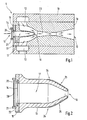
- FIG. 1 shows a section through an exemplary embodiment of a fluid mixing device
- FIG. 2 shows a detail from FIG. 1
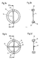
- FIG. 3 a shows a plan view of the heating device according to FIG. 1 or FIG. 2
- FIG. 3 b shows a section through the heating device according to FIG. 3 a along the drawn section line
- FIG 4a shows an alternative embodiment of the heating device according to FIG. 3a
- FIG. 4b shows a section through the heating device according to FIG. 4a along the section line drawn.
- the fluid mixing device 5 is designed as a gas injection valve or mixing nozzle.
- the fluid mixing device 5 is a jet compression nozzle in which a strong, driving flow through the nozzle entrains another, weaker flow.
- hydrogen and saturated water vapor are mixed together in a mixing tube or mixing region within the mixing device 5.
- the fluid mixing device 5 has a main body 18, which is surrounded by a sleeve 19 with an annular channel, via which the main body 18 a first fluid, for example hydrogen or a hydrogen-containing gas, can be fed. Further, a funnel-shaped recess is provided in the base body 18, which opens into a central channel 23, which leads to a funnel-shaped widening output 10 of the fluid mixing device 5.
- the sleeve 19 or the base body 18 according to FIG. 1 is preferably cylindrically symmetrical.
- FIG. 1 further shows how in the region of the inlet 11 of the fluid mixing device 5 a second, in the illustrated example, cartridge-shaped fluid guiding device 13 is inserted into the generated funnel-shaped recess, inside which a second fluid, for example saturated water vapor or a mixture of saturated water vapor a gas is guided.
- a second fluid for example saturated water vapor or a mixture of saturated water vapor a gas is guided.
- the use of the second fluid guiding device 13 in the funnel-shaped recess in the base body 18 further produces a first fluid guiding device 12 into which the first fluid is initially guided separately from the second fluid via the annular channel.
- a mixture of the first fluid guided in the first fluid guiding device 12 and that in the second fluid guiding device 13 guided second fluid then takes place for the first time in a mixing region 16, in which both fluid guide devices 12, 13 open.
- the resulting mixture of fluids is then passed via the central channel 23 to the outlet 10 of the fluid mixing device 5.
- the second fluid guiding device 13 can alternatively also be designed in the form of a funnel or a nozzle. However, the second fluid is always guided in a second fluid-guiding region 17 in the interior of the second fluid-guiding device 13.
- Figure 1 is further shown that in the region of the inlet 11 of the fluid mixing device 5 of the second fluid guide means 13 is preceded by a heater having a first support body 15 which is designed in the form of a retaining ring.
- the heating device has an electrically heated heating wire 14, which is electrically heated with conventional connection contacts 22 with components not shown in operation of the fluid mixing device 5 in a known manner.
- the heater is preceded by a means for generating a turbulence in the second fluid, which is formed in concrete by a second support body 21 in the form of a support ring and a turbulence generator 20 connected to this support ring or second support body 21.
- the turbulence generator 20 is for example a rod, in particular a round rod, a pinhole, a sieve, a shower head or an arrangement or combination of these elements.
- the turbulence generator 20 has the task of generating a turbulence in the second fluid outgoing from the inlet 11, which is supplied to the fluid mixing device 5, so that a particularly effective and uniform heating of the second fluid takes place via the downstream heating device or by means of the heated heating wire 14, before the second fluid then enters the mixing region 16 via the second fluid guiding device 13, where it is mixed with the first fluid.
- FIG. 2 enlarges the second fluid guiding device 13 as well as the heating device and the means for generating the turbulence according to FIG.
- the second fluid guiding device 13 is provided with a coating 25 on its outer side 24, which is in contact with the first fluid guided in the first fluid guiding device 12.
- This coating 25 is provided above all in the mouth region of the second fluid guiding device 13, i. the area that lies in an environment of the mixing area 16.
- the coating 25 is for example a Teflon coating and serves to prevent adhesion, in particular precipitation or condensation of a fluid on the outer side 24 of the second fluid guiding device 13.
- FIG. 3 a shows a top view of the heating device according to FIGS. 1 and 2, wherein it can be seen that the heating device is formed by the retaining ring 15 and the heating wire 14, which runs along a diameter of the retaining ring 15.
- FIG. 3b shows more clearly the connection contacts 22 for the electrical heating of the first heating wire 14th
- FIG. 4 a illustrates an embodiment of the heating device that is an alternative to FIG. 3 a, wherein two heating wires 14, 14 'running perpendicular to one another are provided, which are each electrically heated via corresponding connection contacts 22.
- FIG. 4b also shows that the first heating wire 14 and the second heating wire 14 'are arranged at a distance one behind the other.
- the second support body 21 or support ring, apart from the terminal contacts 22, is made of an insulating material.
- the first heating wire 14 and the second heating wire 14 'intersect they are insulated from one another.
- This insulation may for example be an insulating plate arranged between the heating wires 14, 14 'in the crossing region or an insulating covering of one of the heating wires 14, 14' mounted in this region.
- the flow of the two fluids in the fluid mixing device 5 is greatly accelerated in the above-described embodiments, especially in the mixing region 16, so that there occurs a flow velocity, which is typically close to the speed of sound.
- a flow velocity typically close to the speed of sound.
- the heater by preventive or mixing the previous heating of the second fluid, ie, for example, supplied as a second fluid saturated water vapor on counteracts a higher temperature.
- the temperature of the fluid mixture exiting in the region of the outlet 10 is higher than the saturation temperature of water vapor, so that water condensation can not occur there.
- this fluid mixing device 5 a downstream fuel cell, for the chemical reaction with hydrogen humidified hydrogen is required, reliably and without operating betreibar.
Landscapes
- Engineering & Computer Science (AREA)
- Chemical & Material Sciences (AREA)
- Chemical Kinetics & Catalysis (AREA)
- Combustion & Propulsion (AREA)
- Mechanical Engineering (AREA)
- General Engineering & Computer Science (AREA)
- Manufacturing & Machinery (AREA)
- Sustainable Development (AREA)
- Sustainable Energy (AREA)
- Electrochemistry (AREA)
- General Chemical & Material Sciences (AREA)
- Life Sciences & Earth Sciences (AREA)
- Accessories For Mixers (AREA)
- Nozzles (AREA)
- Fuel Cell (AREA)
Abstract
Description
- Die Erfindung betrifft eine Vorrichtung zur Vermischung von Fluiden, insbesondere ein Gaseinspritzventil, eine Mischungsdüse oder eine Jetkompressionsdüse, beispielsweise zur Verwendung als Brennstoffzuführung in einer Brennstoffzelle, nach der Gattung des Hauptanspruches.
- Beim Betrieb von Brennstoffzellen ist bekannt, diesen ein Gemisch aus Wasserstoff und gesättigtem Wasserdampf zuzuführen, wobei die Gemischmenge von Wasserstoff und gesättigtem Wasserdampf sowie dessen Zusammensetzung über ein Düsenventil zudosiert bzw. eingestellt wird.
- Dabei tritt vielfach das Problem auf, dass der zugeführte Wasserdampf innerhalb der Düse bzw. innerhalb des Düsenventils kondensiert, was zu einem Einfrieren und damit zu einer Düsenverstopfung bzw. einem Ausfall der Funktionalität der Düse und der nachgeschalteten Brennstoffzelle oder zu einer deutlichen Reduzierung des Wirkungsgrades der Düse führt.
- Diesbezüglich ist aus der
GB 2 149 082 A - Aufgabe der vorliegenden Erfindung ist die Bereitstellung einer Vorrichtung gemäß Anspruch 1 zur Vermischung von Fluiden, insbesondere zur Vermischung von Wasserstoff und insbesondere gesättigtem Wasserdampf, die auch als Brennstoffzuführung in einer Brennstoffzelle einsetzbar ist, bei der ein Ausfall durch Vereisung oder Kondensation unterbleibt.
- Die erfindungsgemäße Vorrichtung zur Vermischung von Fluiden hat den Vorteil, dass eine Reduzierung des Wirkungsgrades oder ein Ausfall beim Betrieb beispielsweise durch Kondensation, Verstopfung oder Vereisung wirksam unterdrückt wird, so dass insgesamt eine gegenüber dem Stand der Technik erheblich verbesserte Betriebssicherheit und Zuverlässigkeit erreicht wird. Insbesondere ist im Fall der erfindungsgemäßen Vorrichtung gewährleistet, dass es nicht zu einer Vereisung durch Kondensation von Wasser in deren Austrittsbereich kommt.
- Vorteilhafte Weiterbildungen der Erfindung ergeben sich aus den in den Unteransprüchen genannten Maßnahmen.
- So ist besonders vorteilhaft, wenn das Mittel zur Erzeugung der Turbulenz einen der Strömung des Fluids ausgesetzten bzw. in diese eingebrachten Körper, insbesondere einen Stab oder eine Anordnung von Stäben, einen Ring oder eine Anordnung von Ringen, ein Plättchen, eine Lochblende, einen Duschkopf oder ein Sieb aufweist, der insbesondere möglichst unmittelbar vor der Heizeinrichtung derart angeordnet ist, dass durch die darüber erzeugte Turbulenz eine besonders effektive Wärmeübertragung von der Heizeinrichtung in das die Heizeinrichtung umströmende Fluid erreicht wird. Zudem wird auf diese Weise das der erfindungsgemäßen Vorrichtung zugeführte Fluid auch gleichmäßiger aufgeheizt. Besonders vorteilhaft ist in diesem Zusammenhang, wenn die Heizeinrichtung unmittelbar nach dem Mittel zur Erzeugung der Turbulenz, insbesondere beabstandet parallel dazu, angeordnet ist. Im Übrigen wird eine besonders einfache Aufheizung des Fluids durch Einsatz einer elektrischen Heizeinrichtung, beispielsweise mit einem Heizdraht, einem Heizring oder einer entsprechenden Anordnung von Drähten oder Ringen, erreicht.
- Eine besonders effektive Anordnung der ersten Fluidführungseinrichtung und der zweiten Fluidführungseinrichtung ergibt sich dadurch, dass die erste Fluidführungseinrichtung zumindest bereichsweise von einer zylindersymmetrischen Ausnehmung in einem vorzugsweise metallischen Grundkörper gebildet wird, die in einem in den Grundkörper eingebrachten Zentralkanal mündet, wobei sich der Zentralkanal im Weiteren dann in Richtung auf den Ausgang der Fluidmischvorrichtung vorzugsweise trichterförmig aufweitet. Die zweite Fluidführungseinrichtung ist dann bevorzugt symmetrisch in diese Ausnehmung des Grundkörpers eingesetzt, so dass das darin geführte zweite Fluid ebenfalls in den Zentralkanal mündet.
- Als besonders vorteilhaft hat sich dabei herausgestellt, wenn die erste Fluidführungseinrichtung und/oder die zweite Fluidführungseinrichtung, insbesondere beide, zumindest näherungsweise die Form einer Düse oder bevorzugt eines Trichters oder einer Patrone aufweisen.
- Insbesondere werden die erste Fluidführungseinrichtung und die zweite Fluidführungseinrichtung bevorzugt derart ausgebildet und angeordnet, dass die zweite Fluidführungseinrichtung das darin geführte zweite Fluid in den Zentralkanal eindüst, und dabei an dieser Stelle mit dem in der ersten Fluidführungseinrichtung geführten ersten Fluid vermischt. Insofern treffen sich das erste Fluid und das zweite Fluid zur Vermischung erstmals in einem Mischungsbereich im Bereich des Zentralkanals.
- Vorteilhaft ist weiterhin, wenn mindestens eine der Fluidführungseinrichtungen zumindest bereichsweise oberflächlich mit einer Beschichtung, insbesondere einer Teflonbeschichtung, versehen ist, die einem Anhaften, einem Niederschlag oder einer Kondensation des in der Fluidführungseinrichtung geführten Fluids oder eines auf der Außenseite der Fluidführungseinrichtung mit dieser in Kontakt stehenden Fluids entgegenwirkt.
- Besonders vorteilhaft ist dabei, wenn die in die Ausnehmung des Grundkörpers eingesetzte zweite Fluidführungseinrichtung auf ihrer Außenseite zumindest bereichsweise, insbesondere in einer Umgebung des Mischungsbereiches bzw. der Mündung der ersten Fluidführungseinrichtung und der zweiten Fluidführungseinrichtung in den Zentralkanal, mit der erläuterten Beschichtung versehen ist. Auf diese Weise wird gerade in dem kritischen Mischungsbereich gezielt einer Kondensation von Wasserdampf und insbesondere einer Vereisung durch eine Temperaturabsenkung beim Eindüsen entgegengewirkt.
- Die Erfindung wird anhand der Zeichnungen und in der nachfolgenden Beschreibung näher erläutert. Es zeigt Figur 1 einen Schnitt durch ein Ausführungsbeispiel einer Fluidmischvorrichtung, Figur 2 einen Ausschnitt aus Figur 1, Figur 3a eine Draufsicht auf die Heizeinrichtung gemäß Figur 1 oder Figur 2, Figur 3b einen Schnitt durch die Heizeinrichtung gemäß Figur 3a entlang der eingezeichneten Schnittlinie, Figur 4a eine alternative Ausführungsform der Heizeinrichtung gemäß Figur 3a, und Figur 4b einen Schnitt durch die Heizeinrichtung gemäß Figur 4a entlang der eingezeichneten Schnittlinie.
- Die Figur 1 zeigt eine Fluidmischvorrichtung 5, die als Gaseinspritzventil bzw. Mischungsdüse ausgeführt ist. Insbesondere ist die Fluidmischvorrichtung 5 eine Jetkompressionsdüse, bei der eine starke, treibende Strömung durch die Düse eine andere, schwächere Strömung mitschleppt. Beispielsweise werden in der erläuterten Fluidmischvorrichtung 5 Wasserstoff und gesättigter Wasserdampf in einem Durchmischungsrohr bzw. Vermischungsbereich innerhalb der Mischvorrichtung 5 miteinander vermischt.
- Die Fluidmischvorrichtung 5 weist dazu einen Grundkörper 18 auf, der von einer Hülse 19 mit einem Ringkanal umgeben ist, über den dem Grundkörper 18 ein erstes Fluid, beispielsweise Wasserstoff oder ein wasserstoffhaltiges Gas, zuführbar ist. Weiter ist in dem Grundkörper 18 eine trichterförmige Ausnehmung vorgesehen, die in einen Zentralkanal 23 mündet, der zu einem sich trichterförmig aufweitenden Ausgang 10 der Fluidmischvorrichtung 5 führt. Die Hülse 19 bzw. der Grundkörper 18 gemäß Figur 1 ist bevorzugt zylindersymmetrisch aufgebaut.
- Die Figur 1 zeigt weiter, wie im Bereich des Eingangs 11 der Fluidmischvorrichtung 5 in die erzeugte trichterförmige Ausnehmung eine zweite, im erläuterten Beispiel patronenförmig ausgebildete Fluidführungseinrichtung 13 eingesetzt ist, in deren Innerem ein zweites Fluid, beispielsweise gesättigter Wasserdampf oder eine Mischung von gesättigtem Wasserdampf mit einem Gas, geführt ist.
- Durch den Einsatz der zweiten Fluidführungseinrichtung 13 in die trichterförmige Ausnehmung in dem Grundkörper 18 entsteht weiter eine erste Fluidführungseinrichtung 12, in die über den Ringkanal das erste Fluid zunächst getrennt von dem zweiten Fluid geführt ist.
- Eine Mischung des in der ersten Fluidführungseinrichtung 12 geführten ersten Fluids und des in der zweiten Fluidführungseinrichtung 13 geführten zweiten Fluids erfolgt dann erstmals in einem Mischungsbereich 16, in den beide Fluidführungseinrichtungen 12, 13 münden.
- Von dem Mischungsbereich 16 wird danach das entstandene Gemisch der Fluide über den Zentralkanal 23 zum Ausgang 10 der Fluidmischvorrichtung 5 geführt.
- An dieser Stelle sei betont, dass die zweite Fluidführungseinrichtung 13 alternativ auch in Form eines Trichters oder einer Düse ausgebildet sein kann. Dabei ist aber stets das zweite Fluid in einem zweiten Fluidführungsbereich 17 im Inneren der zweiten Fluidführungseinrichtung 13 geführt.
- In Figur 1 ist weiter dargestellt, dass im Bereich des Eingangs 11 der Fluidmischvorrichtung 5 der zweiten Fluidführungseinrichtung 13 eine Heizeinrichtung vorgeschaltet ist, die einen ersten Tragkörper 15 aufweist, der in Form eines Halteringes ausgeführt ist. Daneben besitzt die Heizeinrichtung einen elektrisch beheizten Heizdraht 14, der mit üblichen Anschlusskontaktierungen 22 mit nicht dargestellten Bauteilen bei Betrieb der Fluidmischvorrichtung 5 in bekannter Weise elektrisch beheizt wird.
- Schließlich ist der Heizeinrichtung ein Mittel zur Erzeugung einer Turbulenz in dem zweiten Fluid vorgeschaltet, das im Konkreten von einem zweiten Tragkörper 21 in Form eines Tragringes und einem mit diesem Tragring bzw. zweiten Tragkörper 21 verbundenen Turbulenzerzeuger 20 gebildet wird.
- Der Turbulenzerzeuger 20 ist beispielsweise ein Stab, insbesondere ein Rundstab, eine Lochblende, ein Sieb, ein Duschkopf oder eine Anordnung oder Kombination dieser Elemente.
- Der Turbulenzerzeuger 20 hat die Aufgabe, in dem von dem Eingang 11 ausgehenden, der Fluidmischvorrichtung 5 zugeführten zweiten Fluid eine Turbulenz zu erzeugen, so dass über die nachgeschaltete Heizeinrichtung bzw. mittels des beheizten Heizdrahtes 14 eine besonders effektive und gleichmäßig Aufheizung des zweiten Fluides erfolgt, bevor das zweite Fluid dann über die zweite Fluidführungseinrichtung 13 in den Mischungsbereich 16 eintritt, und dort mit dem ersten Fluid vermischt wird.
- Die Figur 2 die zweite Fluidführungseinrichtung 13 sowie die Heizeinrichtung und das Mittel zur Erzeugung der Turbulenz gemäß Figur 1 vergrößert. Insbesondere ist dort erkennbar, dass die zweite Fluidführungseinrichtung 13 auf ihrer Außenseite 24, die mit dem in der ersten Fluidführungseinrichtung 12 geführten ersten Fluid in Kontakt steht, mit einer Beschichtung 25 versehen ist.
- Diese Beschichtung 25 ist vor allem in dem Mündungsbereich der zweiten Fluidführungseinrichtung 13 vorgesehen, d.h. dem Bereich, der in einer Umgebung des Mischungsbereiches 16 liegt.
- Die Beschichtung 25 ist beispielsweise eine Teflonbeschichtung und dient dazu, ein Anhaften, insbesondere einen Niederschlag oder eine Kondensation eines Fluids auf der Außenseite 24 der zweiten Fluidführungseinrichtung 13 zu vermeiden.
- Die Figur 3a zeigt eine Draufsicht auf die Heizeinrichtung gemäß den Figuren 1 bzw. 2, wobei erkennbar ist, dass die Heizeinrichtung von dem Haltering 15 und dem Heizdraht 14 gebildet wird, der entlang eines Durchmessers des Halteringes 15 verläuft. Die Figur 3b zeigt deutlicher die Anschlusskontaktierungen 22 zur elektrischen Beheizung des ersten Heizdrahtes 14.
- Die Figur 4a erläutert eine zu Figur 3a alternative Ausführungsform der Heizeinrichtung, wobei zwei zueinander senkrecht verlaufende Heizdrähte 14, 14' vorgesehen sind, die jeweils über entsprechende Anschlusskontaktierungen 22 elektrisch beheizt werden. Die Figur 4b zeigt zudem, dass der erste Heizdraht 14 bzw. der zweite Heizdraht 14' beabstandet hintereinander angeordnet sind.
- Im Übrigen sei noch darauf hingewiesen, dass der zweite Tragkörper 21 bzw. Tragring, abgesehen von den Anschlusskontaktierungen 22, aus einem isolierenden Material ausgeführt ist. Zudem ist in dem Ausführungsbeispiel gemäß den Figuren 4a bzw. 4b bevorzugt vorgesehen, dass in dem Bereich, in dem sich der erste Heizdraht 14 und der zweite Heizdraht 14' kreuzen, diese gegeneinander isoliert werden. Diese Isolierung kann beispielsweise eine zwischen den Heizdrähten 14, 14' im Kreuzungsbereich angeordnete isolierende Platte oder eine in diesem Bereich angebrachte isolierende Umhüllung eines der Heizdrähte 14, 14' sein.
- Die Strömung der beiden Fluide in der Fluidmischvorrichtung 5 wird bei den vorstehend erläuterten Ausführungsbeispielen vor allem im Mischungsbereich 16 stark beschleunigt, so dass dort eine Strömungsgeschwindigkeit auftritt, die typischerweise in der Nähe der Schallgeschwindigkeit liegt. Mit der Zunahme der Strömungsgeschwindigkeit ist in einer Umgebung des Mischungsbereiches 16 gleichzeitig auch eine Annahme des Druckes und der Temperatur der Fluide verbunden, so dass die abgesenkte Temperatur am Ausgang 10 der Fluidmischvorrichtung 5 vielfach unterhalb der dem Druck am Ausgang 10 entsprechenden Sättigungstemperatur von Wasserdampf liegt. Insofern kann es dann, wenn die Temperatur des Fluidgemisches am Ausgang 10 unterhalb der Temperatur liegt, bei der Wasserdampf kondensiert, bei dem dort herrschenden Druck zum Einfrieren der Fluidmischvorrichtung 5 kommen, der die Heizeinrichtung durch präventive oder der Vermischung vorausgehende Aufheizung des zweiten Fluids, d.h. des beispielsweise als zweites Fluid zugeführten gesättigten Wasserdampfes, auf eine höhere Temperatur entgegenwirkt.
- Konkret tritt im Fall der erläuterten Beispiele im Bereich des Ausgangs 10 der Fluidmischvorrichtung 5 bei Betrieb ohne die Heizeinrichtung eine gegenüber der am Eingang 11 herrschenden Temperatur um ca. 45°C verringerte Temperatur auf. Die Aufheizung des zweiten Fluides mit der Heizeinrichtung wird dann so geregelt, dass das Fluidgemisch am Ausgang 10 stets eine Temperatur aufweist, bei gesättigter Wasserdampf nicht kondensiert bzw. der Wasserdampf dort überhitzt ist.
- Insgesamt wird durch die erläuterte Fluidmischvorrichtung 5 erreicht, dass die Temperatur des im Bereich des Ausgangs 10 austretenden Fluidgemisches höher liegt als die Sättigungstemperatur von Wasserdampf, so dass eine Wasserkondensation dort nicht auftreten kann. Damit ist mit dieser Fluidmischvorrichtung 5 eine nachgeschaltete Brennstoffzelle, für deren chemische Reaktion mit Wasserdampf befeuchteter Wasserstoff erforderlich ist, zuverlässig und ohne Störungen betreibar.
Claims (12)
- Vorrichtung zur Vermischung von Fluiden, insbesondere Gaseinspritzventil, Mischungsdüse oder Jetkompressionsdüse, mit einer ersten Fluidführungseinrichtung (12) zur Führung eines ersten Fluids und einer zweiten Fluidführungseinrichtung (13) zur Führung eines zweiten Fluids, wobei die Fluide in einem mit den Fluidführungseinrichtungen (12, 13) in Verbindung stehenden Mischungsbereich (16) miteinander vermischt werden, und wobei mindestens einer der Fluidführungseinrichtungen (12, 13) ein Mittel (20) zur Erzeugung einer Turbulenz in dem betreffenden Fluid und eine dem Mittel (20) zur Erzeugung der Turbulenz hinsichtlich der Strömungsrichtung des betreffenden Fluids nachgeordnete Heizeinrichtung zugeordnet ist, mit der das Fluid vor Erreichen des Mischungsbereiches (16) aufheizbar ist, dadurch gekennzeichnet, dass mindestens eine der Fluidführungseinrichtungen (12, 13) zumindest bereichsweise oberflächlich mit einer Beschichtung (25) insbesondere aus Teflon, versehen ist, die einem Anhaften, einem Niederschlag oder einer Kondensation des betreffenden Fluids oder darin enthaltener Bestandteile entgegenwirkt.
- Vorrichtung nach Anspruch 1, dadurch gekennzeichnet, dass das Mittel (20) zur Erzeugung der Turbulenz ein der Strömung des Fluids ausgesetzter oder in diese eingebrachter Körper, insbesondere ein Stab (20) oder eine Anordnung von Stäben, ein Ring oder eine Anordnung von Ringen, ein Plättchen, eine Lochblende, einen Duschkopf oder ein Sieb aufweist.
- Vorrichtung nach Anspruch 1 oder 2, dadurch gekennzeichnet, dass das Mittel (20) zur Erzeugung der Turbulenz derart ausgebildet und/oder angeordnet ist, dass eine möglichst effektive Aufheizung des anschließend der Heizeinrichtung ausgesetzten Fluids erfolgt.
- Vorrichtung nach einem der vorangehenden Ansprüche, dadurch gekennzeichnet, dass die Heizeinrichtung unmittelbar nach dem Mittel (20) zur Erzeugung der Turbulenz, insbesondere beabstandet parallel dazu, angeordnet ist.
- Vorrichtung nach einem der vorangehenden Ansprüche, dadurch gekennzeichnet, dass die Heizeinrichtung eine elektrische Heizeinrichtung ist, und einen Heizdraht (14, 14') oder Heizring oder eine Anordnung von Heizdrähten (14, 14') oder Heizringen aufweist.
- Vorrichtung nach einem der vorangehenden Ansprüche, dadurch gekennzeichnet, dass die erste Fluidführungseinrichtung (12) zumindest bereichsweise von einer insbesondere zylindersymmetrischen Ausnehmung in einem Grundkörper (18) gebildet ist, die in einem in den Grundkörper (18) eingebrachten Zentralkanal (23) mündet.
- Vorrichtung nach Anspruch 6, dadurch gekennzeichnet, dass der Zentralkanal (20) zu einem Ausgang (10) der Fluidmischvorrichtung (5) führt und sich in einer Umgebung des Ausgangs (10) insbesondere trichterförmig aufweitet.
- Vorrichtung nach Anspruch 6 oder 7, dadurch gekennzeichnet, dass die zweite Fluidführungseinrichtung (13) insbesondere symmetrisch in die Ausnehmung des Grundkörpers (18) eingesetzt ist, und in den in den Grundkörper (18) eingebrachten Zentralkanal (23) mündet.
- Vorrichtung nach einem der vorangehenden Ansprüche, dadurch gekennzeichnet, dass die erste Fluidführungseinrichtung (12) und/oder die zweite Fluidführungseinrichtung (13) zumindest die Form eines Trichters, einer Patrone oder einer Düse aufweist.
- Vorrichtung nach einem der vorangehenden Ansprüche, dadurch gekennzeichnet, dass die zweite Fluidführungseinrichtung (13) das darin geführte zweite Fluid in dem Mischungsbereich (16) in den Zentralkanal (23) eindüst und dabei mit dem in der ersten Fluidführungseinrichtung (12) geführten ersten Fluid vermischt.
- Vorrichtung nach Anspruch 11, dadurch gekennzeichnet, dass die in die Ausnehmung des Grundkörpers (18) eingesetzte zweite Fluidführungseinrichtung (13), die auf ihrer Außenseite (24) mit dem ersten Fluid in Kontakt ist, auf dieser Außenseite (24) zumindest bereichsweise, insbesondere in einer Umgebung des Mischungsbereiches (16), mit der Beschichtung (25) versehen ist.
- Verwendung der Vorrichtung nach einem vorangehenden Ansprüche als Gaseinspritzventil, Düsenventil, Jetkompressor oder zur Brennstoffzuführung in einer Brennstoffzelle, insbesondere zur Vermischung von Wasserstoff und Wasserdampf.
Applications Claiming Priority (3)
| Application Number | Priority Date | Filing Date | Title |
|---|---|---|---|
| DE10138006 | 2001-08-02 | ||
| DE10138006A DE10138006C1 (de) | 2001-08-02 | 2001-08-02 | Vorrichtung zur Vermischung von Fluiden |
| PCT/DE2002/002723 WO2003013712A1 (de) | 2001-08-02 | 2002-07-24 | Vorrichtung zur vermischung von fluiden |
Publications (2)
| Publication Number | Publication Date |
|---|---|
| EP1414558A1 EP1414558A1 (de) | 2004-05-06 |
| EP1414558B1 true EP1414558B1 (de) | 2007-10-10 |
Family
ID=7694194
Family Applications (1)
| Application Number | Title | Priority Date | Filing Date |
|---|---|---|---|
| EP02754430A Expired - Lifetime EP1414558B1 (de) | 2001-08-02 | 2002-07-24 | Vorrichtung zur vermischung von fluiden |
Country Status (6)
| Country | Link |
|---|---|
| US (1) | US6994276B2 (de) |
| EP (1) | EP1414558B1 (de) |
| JP (1) | JP2004536711A (de) |
| CN (1) | CN1246073C (de) |
| DE (2) | DE10138006C1 (de) |
| WO (1) | WO2003013712A1 (de) |
Families Citing this family (37)
| Publication number | Priority date | Publication date | Assignee | Title |
|---|---|---|---|---|
| ES2348020T3 (es) * | 2004-07-09 | 2010-11-26 | Nestec S.A. | Sistema y dispositivo para la preparación y suministro de productos alimenticios a partir de una mezcla compuesta de un liquido alimenticio y un diluyente. |
| EP1647325A1 (de) * | 2004-10-12 | 2006-04-19 | Biotek Technology Corp. | Druckgas-wasser Mischer |
| FR2918299B1 (fr) * | 2007-07-06 | 2011-04-15 | Lvmh Rech | Dispositif de pulverisation a effet venturi et son utilisation en cosmetologie et en parfumerie |
| US8568018B2 (en) * | 2007-12-20 | 2013-10-29 | Rave N.P., Inc. | Fluid injection assembly for nozzles |
| US20100143700A1 (en) * | 2008-12-08 | 2010-06-10 | Victor K Champagne | Cold spray impact deposition system and coating process |
| CN101513595B (zh) * | 2009-01-15 | 2012-01-25 | 中国纺织工业设计院 | 多级、多向y型射流撞击混合器 |
| JP2012187438A (ja) * | 2009-07-11 | 2012-10-04 | Horiba Stec Co Ltd | ガス混合装置 |
| US8496786B2 (en) * | 2009-12-15 | 2013-07-30 | Stone & Webster Process Technology, Inc. | Heavy feed mixer |
| KR101814096B1 (ko) | 2010-02-23 | 2018-01-02 | 아사히 유키자이 가부시키가이샤 | 인라인형 유체 혼합 장치 |
| SE535185E (sv) * | 2010-09-10 | 2019-03-07 | Ovivo Luxembourg Sarl | Apparat för att blanda in en andra fluid i en första fluid innefattande en reglerenhet |
| WO2012112774A1 (en) | 2011-02-16 | 2012-08-23 | Casper Thomas J | Venturi device and method |
| CN103244470A (zh) * | 2011-05-11 | 2013-08-14 | 任文华 | 无叶风扇 |
| US9114367B1 (en) * | 2012-01-09 | 2015-08-25 | Alfa Laval Vortex, Inc. | Apparatus for mixing fluids |
| USD778667S1 (en) | 2012-02-16 | 2017-02-14 | Thomas J Casper | Venturi device |
| US9272817B2 (en) * | 2012-09-28 | 2016-03-01 | Nicholas Becker | Liquid-dispensing systems with integrated aeration |
| CN103510073A (zh) * | 2013-09-28 | 2014-01-15 | 无锡荣能半导体材料有限公司 | 一种气体混合器 |
| US9956532B2 (en) * | 2013-11-07 | 2018-05-01 | U.S. Department Of Energy | Apparatus and method for generating swirling flow |
| CN105270670A (zh) * | 2014-07-11 | 2016-01-27 | 中山市雅西环保科技有限公司 | 密封袋抽真空机 |
| US20160045862A1 (en) * | 2014-08-13 | 2016-02-18 | Breen Energy Solutions, L.L.C. | Dry Material Distribution Device for a Duct with Gas Flow |
| US9863371B2 (en) | 2015-08-31 | 2018-01-09 | Robert Bosch Gmbh | Gaseous fuel, EGR and air mixing device and insert |
| DE102016217372A1 (de) * | 2016-09-13 | 2018-03-15 | Robert Bosch Gmbh | Verfahren zur Herstellung einer fibrillierten Materialzusammensetzung |
| KR101947787B1 (ko) * | 2016-12-28 | 2019-02-15 | 한국원자력연구원 | 수소의 동심 제트를 이용한 수소혼합 유도 노즐장치 및 이를 이용한 수소혼합 유도방법 |
| JP6878040B2 (ja) * | 2017-02-20 | 2021-05-26 | 株式会社Soken | 弁装置 |
| CN110770403B (zh) * | 2017-04-14 | 2022-03-22 | 布拉希精密陶瓷股份有限公司 | 转化器烟气炉道的耐火插入件的保持机构 |
| CN108479445B (zh) * | 2018-04-16 | 2020-12-15 | 昆明理工大学 | 一种纳米气体溶胶发生器 |
| CN108971443A (zh) * | 2018-10-12 | 2018-12-11 | 江苏亨通精工金属材料有限公司 | 一种用于铜连铸连轧生产工序的铸造脱模装置 |
| TWI693965B (zh) * | 2019-03-12 | 2020-05-21 | 信紘科技股份有限公司 | 化學液體稀釋方法 |
| DE102019213569A1 (de) * | 2019-09-06 | 2021-03-11 | Lechler Gmbh | Injektionsdüse für eine Sprühvorrichtung und Sprühvorrichtung |
| US11541406B2 (en) * | 2020-03-30 | 2023-01-03 | Medmix Switzerland Ag | Spray nozzle |
| CN111558309B (zh) * | 2020-04-10 | 2022-04-15 | 中国建筑第五工程局有限公司 | 一种多流道射流器及药剂添加系统 |
| CN113823814A (zh) * | 2020-06-19 | 2021-12-21 | 北京亿华通科技股份有限公司 | 集成温控功能的引射器以及燃料电池氢气侧系统架构 |
| CN112121661A (zh) * | 2020-09-21 | 2020-12-25 | 江苏铧德氢能源科技有限公司 | 电堆测试用阳极气体或阴极气体的混气装置 |
| US11517862B2 (en) * | 2020-09-29 | 2022-12-06 | Trusval Technology Co., Ltd. | Fluid mising assembly |
| CN112902171B (zh) * | 2021-02-03 | 2023-07-11 | 沈阳理工大学 | 一种双旋燃烧器 |
| DE102021207648A1 (de) | 2021-07-19 | 2023-01-19 | Ekpo Fuel Cell Technologies Gmbh | Strahlpumpe und Brennstoffzellensystem |
| CN113385028A (zh) * | 2021-07-27 | 2021-09-14 | 烟台宏远氧业股份有限公司 | 一种二氧化碳吸收装置及方法 |
| CN115155353B (zh) * | 2022-06-10 | 2023-11-24 | 中国石油化工股份有限公司 | 一种用于混合乙烯与氧气的混合器 |
Family Cites Families (11)
| Publication number | Priority date | Publication date | Assignee | Title |
|---|---|---|---|---|
| US2101922A (en) * | 1935-02-19 | 1937-12-14 | Stoesling Ludwig | Spraying apparatus |
| US2905234A (en) * | 1955-05-09 | 1959-09-22 | Dortmund Hoerder Huttenunion A | Apparatus for the combustion of liquid fuels |
| GB848203A (en) * | 1956-06-23 | 1960-09-14 | Frank Wykes | Improvements in and relating to liquid fuel burning devices |
| US3194191A (en) * | 1963-11-18 | 1965-07-13 | John Hydock | Powder feed welding torch |
| DE2356769A1 (de) * | 1973-11-14 | 1975-06-05 | Schladitz Hutzenlaub Gbr | Brenner fuer fluessige brennstoffe |
| US4472134A (en) * | 1980-02-15 | 1984-09-18 | Electro Vapor Energy Corp. | Vaporizing fuel oil burner |
| DE3106911A1 (de) * | 1981-02-24 | 1982-09-09 | Skw Trostberg Ag, 8223 Trostberg | Verfahren zum verbrennen von organische bestandteile enthaltendem abwasser |
| GB2149082B (en) * | 1983-11-04 | 1988-05-18 | Consultant Gas Eng Ltd | Burners |
| IN170251B (de) * | 1987-04-16 | 1992-03-07 | Luminis Pty Ltd | |
| US4919853A (en) * | 1988-01-21 | 1990-04-24 | The United States Of America As Represented By The United States Department Of Energy | Apparatus and method for spraying liquid materials |
| SE520988C2 (sv) * | 1998-11-12 | 2003-09-16 | Stihl Maschf Andreas | Handfört arbetsredskap med generator |
-
2001
- 2001-08-02 DE DE10138006A patent/DE10138006C1/de not_active Expired - Fee Related
-
2002
- 2002-07-24 EP EP02754430A patent/EP1414558B1/de not_active Expired - Lifetime
- 2002-07-24 JP JP2003518707A patent/JP2004536711A/ja active Pending
- 2002-07-24 CN CNB028030796A patent/CN1246073C/zh not_active Expired - Lifetime
- 2002-07-24 US US10/381,384 patent/US6994276B2/en not_active Expired - Lifetime
- 2002-07-24 DE DE50211060T patent/DE50211060D1/de not_active Expired - Lifetime
- 2002-07-24 WO PCT/DE2002/002723 patent/WO2003013712A1/de not_active Ceased
Non-Patent Citations (1)
| Title |
|---|
| None * |
Also Published As
| Publication number | Publication date |
|---|---|
| US6994276B2 (en) | 2006-02-07 |
| CN1476350A (zh) | 2004-02-18 |
| WO2003013712A1 (de) | 2003-02-20 |
| DE10138006C1 (de) | 2003-04-24 |
| EP1414558A1 (de) | 2004-05-06 |
| CN1246073C (zh) | 2006-03-22 |
| US20040056112A1 (en) | 2004-03-25 |
| JP2004536711A (ja) | 2004-12-09 |
| DE50211060D1 (de) | 2007-11-22 |
Similar Documents
| Publication | Publication Date | Title |
|---|---|---|
| EP1414558B1 (de) | Vorrichtung zur vermischung von fluiden | |
| EP2018904A1 (de) | Vorrichtung zum Mischen von Wasser und Gas | |
| EP0693793A2 (de) | Verfahren und Vorrichtung zum dosierten Zuführen von Methanol und/oder Wasser zu einem Brennstoffzellensystem | |
| EP1339965B1 (de) | Einspritzeinrichtung zum dosierten einspritzen von zwei flüssigkeiten in einen reaktionsraum | |
| EP1423190A2 (de) | System zum umsetzen von brennstoff und luft zu reformat und verfahren zur montage eines solchen systems | |
| DE2144861C2 (de) | Kosmetikgerät zur dermatologischen Behandlung mit einem Wasserdampf-Ozon-Gemisch | |
| CH695546A5 (de) | Dralldruck-Düse. | |
| WO2011092070A1 (de) | Brennstoffzellensystem mit verbesserter brenngaszirkulation | |
| EP1254699A1 (de) | Durchmischungsvorrichtung für Gas in Brennstoffzellen | |
| DE10054921A1 (de) | Verdampfer-Rohbrennstoff-Einspritzvorrichtung | |
| EP1312789A2 (de) | Doppelter Brennstoffzulauf eines Kraftstoffeinspritzventils | |
| DE102005058530A1 (de) | Reformeranordnung, Funktionssystem aus Reformeranordnung und Wasserstoff verbrauchendem System und Verfahren zum Betreiben einer Reformeranordnung | |
| DE102005022562A1 (de) | Einspritzelement für Einspritzen von unter Druck gesetztem Fluid | |
| AT521519B1 (de) | Brennstoffzellensystem | |
| DE10357474A1 (de) | System zum Umsetzen von Brennstoff und Luft zu Reformat | |
| EP4067742B1 (de) | Verfahren zur befestigung einer gasdüse an einem gasventil, gasdüse und heizgerät | |
| EP0971792B1 (de) | Düse, verwendung einer düse und verfahren zur eindüsung eines ersten fluids in ein zweites fluid | |
| EP1478453B1 (de) | Systeme zum umsetzen von brennstoff und luft zu reformat | |
| WO2011116892A1 (de) | Zweistoff-innenmischdüsenanordnung und verfahren zur zerstäubung einer flüssigkeit | |
| DE102022200045A1 (de) | Verfahren zum Betreiben eines Brennstoffzellensystems, Gasversorgungseinheit sowie Brennstoffzellensystem mit Gasversorgungseinheit | |
| WO2018210984A1 (de) | Fluidmischvorrichtung | |
| DE102006016814A1 (de) | Polarplatte, insbesondere Endplatte oder Bipolarplatte für eine Brennstoffzelle | |
| WO2025114353A1 (de) | Injektor und verbrennungsmotor hiermit | |
| WO2002089995A1 (de) | Zweistoffdüse | |
| DE202012100758U1 (de) | Vorrichtung zur Gemischbereitung |
Legal Events
| Date | Code | Title | Description |
|---|---|---|---|
| PUAI | Public reference made under article 153(3) epc to a published international application that has entered the european phase |
Free format text: ORIGINAL CODE: 0009012 |
|
| 17P | Request for examination filed |
Effective date: 20040302 |
|
| AK | Designated contracting states |
Kind code of ref document: A1 Designated state(s): AT BE BG CH CY CZ DE DK EE ES FI FR GB GR IE IT LI LU MC NL PT SE SK TR |
|
| AX | Request for extension of the european patent |
Extension state: AL LT LV MK RO SI |
|
| 17Q | First examination report despatched |
Effective date: 20040806 |
|
| GRAP | Despatch of communication of intention to grant a patent |
Free format text: ORIGINAL CODE: EPIDOSNIGR1 |
|
| GRAS | Grant fee paid |
Free format text: ORIGINAL CODE: EPIDOSNIGR3 |
|
| GRAA | (expected) grant |
Free format text: ORIGINAL CODE: 0009210 |
|
| AK | Designated contracting states |
Kind code of ref document: B1 Designated state(s): CH DE FR GB IT LI |
|
| REG | Reference to a national code |
Ref country code: GB Ref legal event code: FG4D Free format text: NOT ENGLISH |
|
| REG | Reference to a national code |
Ref country code: CH Ref legal event code: EP |
|
| REF | Corresponds to: |
Ref document number: 50211060 Country of ref document: DE Date of ref document: 20071122 Kind code of ref document: P |
|
| GBV | Gb: ep patent (uk) treated as always having been void in accordance with gb section 77(7)/1977 [no translation filed] | ||
| EN | Fr: translation not filed | ||
| PLBE | No opposition filed within time limit |
Free format text: ORIGINAL CODE: 0009261 |
|
| STAA | Information on the status of an ep patent application or granted ep patent |
Free format text: STATUS: NO OPPOSITION FILED WITHIN TIME LIMIT |
|
| 26N | No opposition filed |
Effective date: 20080711 |
|
| PG25 | Lapsed in a contracting state [announced via postgrant information from national office to epo] |
Ref country code: FR Free format text: LAPSE BECAUSE OF FAILURE TO SUBMIT A TRANSLATION OF THE DESCRIPTION OR TO PAY THE FEE WITHIN THE PRESCRIBED TIME-LIMIT Effective date: 20080725 |
|
| PG25 | Lapsed in a contracting state [announced via postgrant information from national office to epo] |
Ref country code: GB Free format text: LAPSE BECAUSE OF FAILURE TO SUBMIT A TRANSLATION OF THE DESCRIPTION OR TO PAY THE FEE WITHIN THE PRESCRIBED TIME-LIMIT Effective date: 20071010 |
|
| PGFP | Annual fee paid to national office [announced via postgrant information from national office to epo] |
Ref country code: IT Payment date: 20080726 Year of fee payment: 7 |
|
| REG | Reference to a national code |
Ref country code: CH Ref legal event code: PL |
|
| PG25 | Lapsed in a contracting state [announced via postgrant information from national office to epo] |
Ref country code: CH Free format text: LAPSE BECAUSE OF NON-PAYMENT OF DUE FEES Effective date: 20080731 Ref country code: LI Free format text: LAPSE BECAUSE OF NON-PAYMENT OF DUE FEES Effective date: 20080731 |
|
| PG25 | Lapsed in a contracting state [announced via postgrant information from national office to epo] |
Ref country code: IT Free format text: LAPSE BECAUSE OF NON-PAYMENT OF DUE FEES Effective date: 20090724 |
|
| REG | Reference to a national code |
Ref country code: DE Ref legal event code: R079 Ref document number: 50211060 Country of ref document: DE Free format text: PREVIOUS MAIN CLASS: B01F0005040000 Ipc: B01F0025300000 |
|
| PGFP | Annual fee paid to national office [announced via postgrant information from national office to epo] |
Ref country code: DE Payment date: 20210924 Year of fee payment: 20 |
|
| REG | Reference to a national code |
Ref country code: DE Ref legal event code: R071 Ref document number: 50211060 Country of ref document: DE |