EP1414613B1 - Hydraulikkolben aus walzblech und verfahren zu dessen herstellung - Google Patents
Hydraulikkolben aus walzblech und verfahren zu dessen herstellung Download PDFInfo
- Publication number
- EP1414613B1 EP1414613B1 EP02794761A EP02794761A EP1414613B1 EP 1414613 B1 EP1414613 B1 EP 1414613B1 EP 02794761 A EP02794761 A EP 02794761A EP 02794761 A EP02794761 A EP 02794761A EP 1414613 B1 EP1414613 B1 EP 1414613B1
- Authority
- EP
- European Patent Office
- Prior art keywords
- side wall
- blank
- shaped
- punch
- piston
- Prior art date
- Legal status (The legal status is an assumption and is not a legal conclusion. Google has not performed a legal analysis and makes no representation as to the accuracy of the status listed.)
- Expired - Lifetime
Links
Images



Classifications
-
- B—PERFORMING OPERATIONS; TRANSPORTING
- B21—MECHANICAL METAL-WORKING WITHOUT ESSENTIALLY REMOVING MATERIAL; PUNCHING METAL
- B21D—WORKING OR PROCESSING OF SHEET METAL OR METAL TUBES, RODS OR PROFILES WITHOUT ESSENTIALLY REMOVING MATERIAL; PUNCHING METAL
- B21D22/00—Shaping without cutting, by stamping, spinning, or deep-drawing
- B21D22/20—Deep-drawing
- B21D22/21—Deep-drawing without fixing the border of the blank
-
- B—PERFORMING OPERATIONS; TRANSPORTING
- B23—MACHINE TOOLS; METAL-WORKING NOT OTHERWISE PROVIDED FOR
- B23P—METAL-WORKING NOT OTHERWISE PROVIDED FOR; COMBINED OPERATIONS; UNIVERSAL MACHINE TOOLS
- B23P15/00—Making specific metal objects by operations not covered by a single other subclass or a group in this subclass
- B23P15/10—Making specific metal objects by operations not covered by a single other subclass or a group in this subclass pistons
-
- F—MECHANICAL ENGINEERING; LIGHTING; HEATING; WEAPONS; BLASTING
- F16—ENGINEERING ELEMENTS AND UNITS; GENERAL MEASURES FOR PRODUCING AND MAINTAINING EFFECTIVE FUNCTIONING OF MACHINES OR INSTALLATIONS; THERMAL INSULATION IN GENERAL
- F16D—COUPLINGS FOR TRANSMITTING ROTATION; CLUTCHES; BRAKES
- F16D2125/00—Components of actuators
- F16D2125/02—Fluid-pressure mechanisms
- F16D2125/06—Pistons
-
- F—MECHANICAL ENGINEERING; LIGHTING; HEATING; WEAPONS; BLASTING
- F16—ENGINEERING ELEMENTS AND UNITS; GENERAL MEASURES FOR PRODUCING AND MAINTAINING EFFECTIVE FUNCTIONING OF MACHINES OR INSTALLATIONS; THERMAL INSULATION IN GENERAL
- F16D—COUPLINGS FOR TRANSMITTING ROTATION; CLUTCHES; BRAKES
- F16D2200/00—Materials; Production methods therefor
- F16D2200/0004—Materials; Production methods therefor metallic
- F16D2200/0008—Ferro
-
- F—MECHANICAL ENGINEERING; LIGHTING; HEATING; WEAPONS; BLASTING
- F16—ENGINEERING ELEMENTS AND UNITS; GENERAL MEASURES FOR PRODUCING AND MAINTAINING EFFECTIVE FUNCTIONING OF MACHINES OR INSTALLATIONS; THERMAL INSULATION IN GENERAL
- F16D—COUPLINGS FOR TRANSMITTING ROTATION; CLUTCHES; BRAKES
- F16D2250/00—Manufacturing; Assembly
- F16D2250/0023—Shaping by pressure
-
- Y—GENERAL TAGGING OF NEW TECHNOLOGICAL DEVELOPMENTS; GENERAL TAGGING OF CROSS-SECTIONAL TECHNOLOGIES SPANNING OVER SEVERAL SECTIONS OF THE IPC; TECHNICAL SUBJECTS COVERED BY FORMER USPC CROSS-REFERENCE ART COLLECTIONS [XRACs] AND DIGESTS
- Y10—TECHNICAL SUBJECTS COVERED BY FORMER USPC
- Y10T—TECHNICAL SUBJECTS COVERED BY FORMER US CLASSIFICATION
- Y10T29/00—Metal working
- Y10T29/49—Method of mechanical manufacture
- Y10T29/49229—Prime mover or fluid pump making
- Y10T29/49249—Piston making
-
- Y—GENERAL TAGGING OF NEW TECHNOLOGICAL DEVELOPMENTS; GENERAL TAGGING OF CROSS-SECTIONAL TECHNOLOGIES SPANNING OVER SEVERAL SECTIONS OF THE IPC; TECHNICAL SUBJECTS COVERED BY FORMER USPC CROSS-REFERENCE ART COLLECTIONS [XRACs] AND DIGESTS
- Y10—TECHNICAL SUBJECTS COVERED BY FORMER USPC
- Y10T—TECHNICAL SUBJECTS COVERED BY FORMER US CLASSIFICATION
- Y10T29/00—Metal working
- Y10T29/49—Method of mechanical manufacture
- Y10T29/49229—Prime mover or fluid pump making
- Y10T29/49249—Piston making
- Y10T29/49256—Piston making with assembly or composite article making
Definitions
- the invention relates to a hydraulic piston made of rolled sheet, according to the preamble of claim 1 and a method for producing such a piston.
- Pistons of this type are used, for example, in hydraulically actuated vehicle brakes. From the Russian patent 2 163 987 a hydraulic piston according to the preamble of claim 1 is known.
- Pistons of the type mentioned must meet conflicting requirements: On the one hand, they should be light to have a low inertia, on the other hand they must be so stable that at a high level acting on the bottom of the piston Stress, as e.g. with a strong braking due to the high hydraulic pressure occurs in the brake system, there is no radial deformation of the side wall of the Pistons can come. If the last condition is not fulfilled, it can be a complete one Function loss of the piston occur.
- Hydraulic pistons usually have a cylindrical cup shape with an open one The End. In a portion of the outer surface adjacent the open end of the piston the sidewall is often an annular groove, which is used to attach a Protective sleeve is used.
- the area of the annular groove is with regard to a material deformation particularly endangered by stress, because the wall through the groove is weakened.
- a piston produced in the drawing process is known in which the wall thickness in the critical groove area is not smaller than the wall thickness in the remaining areas of the piston.
- Two critical areas are in WO 91/12445 called, on the one hand the area of the groove and on the other hand the inner area of a Spring arrangement. Determine the stability requirements in these two areas the thickness of the piston wall.
- the piston is a hollow construction with an open end. His outer wall is cylindrically shaped and has a groove for fixing a Protective sleeve on.
- the inner surface of the piston is in one at the open end adjacent and extending in the axial direction inwardly over the annular groove Cylindrical shaped area.
- the inner diameter is larger than in the adjacent to the open end Area.
- the thickness of the side wall at the open end is greater than near the piston crown, giving the resistance to axial forces in the critical area of the groove benefits. It's complicated, though Piston with two inner surfaces of different inner diameter and the same Outer diameter, especially because the inner surface with the smaller Inner diameter at the open end of the piston is.
- the invention has for its object to provide a hydraulic piston, the with high stability has a low weight and at the open end sufficient Has wall thickness to ensure the proper transmission of axial forces. Furthermore, the piston should be easy to produce.
- the thickness of the side wall of the piston decreases from that part of the inner surface the side wall adjacent to the open end and a cylindrical one Form, monotone to the piston crown.
- the inner diameter of the hydraulic piston according to the invention monotone.
- the term "monotonous” is here in particular a continuous one Reduction of the sidewall thickness or a continuous increase in the Inside diameter meant.
- Such a designed piston has an excellent Stability against the required load types and can also be easy to make.
- the piston crown is curved inwards, especially concave. Such a curvature of the piston crown ensures a good resistance to the usual workloads.
- the radial Outer part of the piston crown a truncated cone shape and the central or middle Part of the piston crown a spherical cap shape.
- the extension of the frustoconical Part of the piston crown along its profile is preferably not larger Than three times the wall thickness of the side wall in its attached to the piston crown has adjacent section.
- a partly frustoconical, partly spherical cap-shaped Shape of the piston crown is particularly advantageous for the shaping the outer surface of the side wall in the transition region of the side wall to the piston head by compression molding.
- the production method according to the invention comprises in its simplest embodiment the steps of punching out a disc-shaped round blank a piece of rolled sheet, the deep drawing of the disc-shaped round blank in a Cup shape by means of a die and a punch, the molding of the cup-shaped Blank for shaping the piston crown and the cylindrical outer surface of the hydraulic piston, and the incorporation of an annular groove in the outer surface of the Hydraulic piston. It can be seen that in the production process according to the invention Only very little machining is required, for example Generating the annular groove. Basically, however, the piston is made of a rolled sheet produced by drawing and molding operations.
- Deep drawing takes place in several steps.
- the disk-shaped round blank first by means of a first punch by a first circular die opening and then by means of a second punch pressed by a second circular die opening whose diameter is smaller than the diameter of the first die opening.
- the first deep drawing step is a still relatively flat, cup-shaped blank obtained, the inner diameter of the Outer diameter of the stamp used corresponds.
- Material forming changes the thickness of the sheet. She is after the Deep drawing step at the open end greater than in a transition region between Side wall and floor, because there due to the drawing process, the material thickness reduced. The wall thickness reduction from the open end to the transition area between sidewall and floor takes place continuously.
- the cup shape is narrower and higher and it comes to a further reduction of the wall thickness in the transition region from the side wall to Ground.
- the inner diameter of the cup-shaped blank after the second Deep drawing step is determined by the outer diameter of the second determined by the outer diameter of the used in the second deep drawing step Stamp.
- those used in the first and second deep drawing steps Stamp cylindrical.
- the cup-shaped blank by means of a third punch by a third circular die opening pressed, whose diameter is smaller than the diameter the second die opening, the third die one of his free end outgoing first cylindrical section and an adjoining second cylindrical portion whose diameter is larger as the diameter of the first cylindrical section and smaller than the diameter the third die opening is.
- the step in the inner surface is used to in order to the deep drawing into a cup shape by a first molding process a to form inwardly arched piston crown by a stepped punch with the step in the side wall of the blank engages and the blank in pushes a molding die.
- This first molding operation is preferably followed by a fourth deep drawing step, in FIG the cup-shaped blank in turn by means of a stepped punch, the engages the step in the side wall of the blank, by a fourth circular die opening is pressed, whose diameter is smaller than the Diameter of the third die opening is.
- this fourth drawing step the cylindrical outer surface of the side wall shaped.
- the method according to the invention is following the molding of the cylindrical outer surface of the side wall a second molding operation by means of a molding die and a stepped, performed with the step in the side wall of the blank engaging punch, around a transition area between the piston crown and the side wall to shape.
- it is advantageous for the area of the die which contacts the piston crown dome-shaped in the center and frustoconical at the edge.
- a third molding process by means of a Forming die and a turn stepped, with the step in the side wall of the blank engaged punch to the piston crown its final To give shape.
- At least the outer surface can be reworked become.
- Post-processing the outer surface may take one or more steps include.
- the reworking preferably comprises at least one of the steps grinding, coating and polishing.
- a resulting in the production of the hydraulic piston is made by punching out a disk-shaped round blank from a piece of sheet metal, by deep drawing of the disc-shaped round blank into a sheet metal mold using a die and a Stamp, as well as by molding the cup-shaped blank to form the Piston bottom and the cylindrical outer surface of the hydraulic piston.
- Fig. 1 shows a first embodiment of a hydraulic piston 10 for a hydraulic Motor vehicle brake in longitudinal section.
- the piston 10 is hollow and has a open end 12. It consists of a piston head 14, which is integral with a Side wall 16 is connected.
- the side wall 16 has a cylindrical outer surface 18 into which an annular groove 20 is inserted, which is in an open end 12 adjacent end portion the side wall 16 is located.
- the side wall 16 further has an inner surface 22 which in one at the open end 12 adjacent and axially over the annular groove 20 extending portion 24th is cylindrical. From the end of this area 24 to the piston head 14 decreases the thickness of the side wall 16 while maintaining the cylindrical outer shape continuously.
- the dimensions of the hydraulic piston 10 may be according to the intended Purpose to be selected.
- the piston 10 may be, for example, 50.5 mm high and be designed for an operating pressure of at least 160 bar.
- the wall thicknesses a, b and c are then chosen so that the piston 10 in particular in the region of Ring groove 20 is stable against axial loads, without having an optimum wall thickness c is increased, which provides a resistance to both axial compressive forces as well as against radial pressure compression forces.
- the dimension a for example, 1.9 mm
- the dimension b 3.9 mm and the dimension c is 3 mm.
- the cylindrical portion 24 of the inner surface 22nd extends from the open end 12 about 16 mm in the axial direction. Of the Range of continuous wall thickness reduction then extends over a total of 31 mm in the axial direction.
- Fig. 2 illustrates a deep drawing step for making the piston 10.
- a disc-shaped, round blank 26 is punched out of rolled metal (not shown).
- This blank 26 is by means of a cylindrical punch 28 pressed by a die 30 with a circular die opening 32.
- the dimension b is determined by the clearance between the punch 28 and the die 30th Are defined.
- Fig. 2 in the left half of the initial state and in the right Half of the state after performing the deep drawing step shown.
- Fig. 2 deep drawing step does not have to be done at once, but can be distributed to several deep drawing steps.
- a first deep drawing step is then first produces a still relatively flat and wider cup-shaped blank 26, which becomes progressively narrower and higher in subsequent deep drawing steps, to get closer and closer to the final desired shape.
- Fig. 3 shows a subsequent molding step in which the now cup-shaped Blank 26 is pressed by means of another punch 34 in a further die 36 is, to the outer surface 18, the cylindrical shape and the piston head 14 a to to give in vaulted shape.
- the punch 34 has a concave face and the die 36 has a convex bottom.
- Forming step shown are at the same time the outer surface 18 and the piston crown 14 brought into the desired shape.
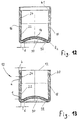
- Fig. 13 shows a second embodiment of a hydraulic piston 10, which is from the in Fig. 1 illustrated embodiment differs in that the piston crown 14 in its central region of a spherical cap and in a radial outer region is frustoconical.
- FIGS. 4 to 11 show a well-suited for the production of the piston of FIG. 13 Method.
- an initial state is on the left and the right side, respectively State reflected, after the execution of the respective processing step results.
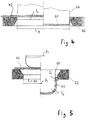
- a punching step is first shown in which a disc-shaped, circular blank 40 from a rolled plate 42 of quality 08Yu a thickness S 0 from here 3.6 mm and a diameter D from here 124 mm by means of a punch 44 and a die 46 is punched out.
- FIG. 5 shows a first deep-drawing step in which the disk-shaped blank 40 is pressed by means of a first punch 48 through a first circular die opening 50 of a die 52 and is thereby shaped like a cup.
- the first punch 48 here has a diameter d 1 of 72 mm
- the first die opening 50 has a diameter D 1 of 80 mm.
- the outer diameter of the now cup-shaped blank 40 at its open end is therefore 80 mm and the wall thickness S 1 in the region of its open end 4 mm.
- the wall thickness continuously decreases due to the drawing process to a value S 2 of approximately 3.5 mm in the transition area between the side wall and the bottom.
- FIG. 6 shows a second deep drawing step in which the blank 40 is brought from an outside diameter of 80 mm to an outside diameter of 65 mm by a second cylindrical punch 54 pushing the cup-shaped blank 40 through a second circular die opening 56 of a die 58.
- the outer diameter d 2 of the second punch 54 is 57 mm, while the diameter D 2 of the second die opening 56 is 65 mm.
- a cup-shaped blank 40 having an inner diameter of 57 mm and an outer diameter is obtained, which continuously decreases from 65 mm at the open end to the bottom.
- the thickness of the side wall therefore decreases from a value S 3 of 4 mm to a value S 4 of 3.45 mm in the region of the transition between the side wall and the bottom.
- Fig. 7 shows a third deep drawing step in which the cup-shaped blank 40 is brought from an outer diameter of 65 mm to an outer diameter of 56.5 mm by a third cylindrical punch 60 presses the blank 40 through a third circular die opening 62 of a die 64 ,
- the outer diameter d 3 of the third punch 58 is 48.6 mm, while the diameter D 3 of the third die opening 62 is 56.5 mm.
- the wall thickness of the side wall of the blank 40 decreases towards its bottom, near the open end of the blank 40 it is determined by the distance between the side wall and the die 64 and has a value S 5 of 3.95 mm, while near the bottom it has a value S 6 of 3.4 mm.
- the third punch 60 has a first cylindrical section forming its free end with the aforementioned outer diameter d 3 of 48.6 mm and an adjoining second cylindrical section having an outer diameter of 53 mm.
- This second, larger diameter portion of the third punch 60 forms a step 41 (see FIG. 12) at the end of the third deep drawing step in the inner surface of the side wall of the blank 40 by reducing the thickness of the side wall near the open end.
- the radial extent of the shaped step is 2.2 mm.
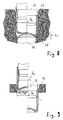
- Fig. 8 shows a first molding step, during which the bottom of the blank 40 is curved inwards.
- a step-shaped punch 66 designed to be complementary to the inner surface of the blank 40 presses the blank 40 into a forming die 68 in that the punch 66 engages with the step 41 formed in the side wall of the blank 40.
- the inner diameter D 4 of the mold die opening is 56.5 mm, so that the outer diameter of the blank 40 is not further reduced by this opening.
- the bottom of the mold die opening is formed by a punch-shaped ejector 70, the blank 40 facing surface is spherical cap. In this way, the bottom of the blank 40 is deformed inwardly to a concavity k 1 of 8 mm. In this case, the part of the side wall adjacent to the bottom is pulled somewhat radially inwards.
- FIG. 9 shows a fourth deep drawing step in which the outer diameter of the blank 40 is brought from 56.5 mm to 54.3 mm by inserting a stepped punch 72 which engages with the step 41 formed on the inner surface of the blank 40, the blank 40 is pressed by a fourth circular die opening 74 of a die 76.
- a first cylindrical section forming the free end of the punch 72 has an outer diameter d 4 of 46.4 mm, while the fourth die opening 74 has a diameter D 5 of 54.3 mm.
- the outer surface of the side wall of the blank 40 is formed into a cylinder having a diameter of 54.3 mm. Due to the free end of the punch 72 forming cylindrical portion with the diameter d 4 and the inner surface of the blank 40 remains cylindrical in this area. In the adjoining region, the inner diameter of the blank 40 increases continuously to the bottom, because the wall thickness of the side wall decreases continuously.
- Fig. 10 shows a second molding step in which the transition region between the sidewall and the bottom of the blank is formed.
- a step-shaped punch 78 engages with the present on the inner surface of the blank 40 shoulder 41 the blank 40 into the opening of a forming die 80, the bottom of which is formed by a punch-like ejector 82.
- the blank 40 facing surface of the ejector 82 is in the center of a spherical cap and frustoconical at the edge.
- the transition region between the side wall and the bottom of the blank 40 abuts the mold die opening and forms a transition radius R 1 of 2 mm.
- the concavity k 1 of 8 mm is maintained.
- the inner diameter of the molding die opening is 54.3 mm, that is, the outer dimension of the blank 40 is not changed.
- a third molding step is shown, in which the bottom of the blank 40 receives its final shape.
- a step-shaped punch 84 formed for engagement with the shoulder 41 in the blank 40 pushes the blank 40 into the opening of a forming die 86, the bottom of which is formed by a punch-shaped ejector 88.
- the concavity is increased to a value k 2 of 9 mm.
- the spherical cap-shaped shape of the bottom of the blank in the middle and the frusto-conical shape of the bottom at the edge is maintained.
- the transition radius between the side wall and the bottom of the blank 40 increases to a value R 2 of 3.4 mm.
- Fig. 12 shows the almost finished hydraulic piston as a blank in longitudinal section. you detects the cylindrical portion 24 of the inner surface 22 extending from the portion 24 to the bottom 14 continuously reducing sidewall thickness, a middle Area 90 of the bottom 14 with spherical cap shape and a truncated cone-shaped edge region 92 of the bottom 14, which extends over a distance d which is no greater than three times the wall thickness of the side wall 16 near the bottom 14 has. Neither the inner surface 22 nor the cylindrical Outside surface 18 must be further processed.
- the outer surface 18 of the hydraulic piston 10 after Forming the annular groove 20 reworked.
- the post-processing can, for example a grinding process and a subsequent coating with a include corrosion and abrasion resistant material.
- the coated outer surface 18 can finally be subjected to a polishing process.
Landscapes
- Engineering & Computer Science (AREA)
- Mechanical Engineering (AREA)
- Pistons, Piston Rings, And Cylinders (AREA)
- Forging (AREA)
- Shaping Metal By Deep-Drawing, Or The Like (AREA)
- Braking Arrangements (AREA)
Abstract
Description
Aus dem russischen Patent 2 163 987 ist ein Hydraulikkolben nach dem Oberbegriff des Anspruchs 1 bekannt.
- Fig. 1
- ein erstes Ausführungsbeispiel eines erfindungsgemäßen Hydraulikkolbens im Längsschnitt,
- Fig. 2
- einen im Rahmen der Herstellung des Kolbens aus Fig. 1 erfolgenden Tiefziehschritt,
- Fig. 3
- ein im Rahmen der Herstellung des Kolbens aus Fig. 1 erfolgenden Formpressschritt,
- Fig. 4
- einen Ausstanzschritt bei der Herstellung des Kolbens aus Fig. 13,
- Fig. 5
- einen ersten Tiefziehschritt bei der Herstellung des Kolbens aus Fig. 13,
- Fig. 6
- einen zweiten Tiefziehschritt bei der Herstellung des Kolbens aus Fig. 13,
- Fig. 7
- einen dritten Tiefziehschritt bei der Herstellung des Kolbens aus Fig. 13,
- Fig. 8
- einen ersten Formpressschritt bei der Herstellung des Kolbens aus Fig. 13,
- Fig. 9
- einen vierten Tiefziehschritt bei der Herstellung des Kolbens aus Fig. 13,
- Fig. 10
- einen zweiten Formpressschritt bei der Herstellung des Kolbens aus Fig. 13,
- Fig. 11
- einen dritten Formpressschritt bei der Herstellung der Kolbens aus Fig. 13,
- Fig. 12
- einen nahezu fertigen Kolben im Längsschnitt, und
- Fig. 13
- ein zweites Ausführungsbeispiel eines erfindungsgemäßen Hydraulikkolbens im Längsschnitt.
Claims (15)
- Becherförmiger Hydraulikkolben (10) aus Walzblech, mitwobei ein Abschnitt (24) der Innenfläche (22) der Seitenwand (16), der an das offene Ende (12) angrenzt und sich in axialer Richtung über die Ringnut (20) erstreckt, eine zylindrische Form aufweist, dadurch gekennzeichnet, dass die Dicke der Seitenwand (16) sich von dem Abschnitt (24) der Innenfläche (22) bis zum Kolbenboden (14) monoton verringert.einem offenen Ende (12),einer Seitenwand (16) mit einer zylindrischen Außenfläche (18) und einer Innenfläche (22), wobei die Seitenwand (16) auf ihrer Außenfläche (18) in einem an das offene Ende (12) angrenzenden Abschnitt mit einer Ringnut (20) versehen ist, undeinem Kolbenboden (14),
- Hydraulikkolben nach Anspruch 1,
dadurch gekennzeichnet, dass der Kolbenboden (14) nach innen gewölbt ist. - Hydraulikkolben nach Anspruch 2,
dadurch gekennzeichnet, dass der Kolbenboden (14) konkav gewölbt ist. - Hydraulikkolben nach Anspruch 2,
dadurch gekennzeichnet, dass der radial äußere Teil des Kolbenbodens (14) eine Kegelstumpfform und der mittlere Teil des Kolbenbodens (14) eine Kugelkalottenform aufweist. - Hydraulikkolben nach Anspruch 4,
dadurch gekennzeichnet, dass die Erstreckung des kegelstumpfförmigen Teils des Kolbenbodens (14) längs seines Profils nicht größer als das Dreifache der Wanddicke ist, die die Seitenwand (16) in ihrem an den Kolbenboden (14) angrenzenden Abschnitt aufweist. - Verfahren zur Herstellung eines Hydraulikkolbens nach einem der vorhergehenden Ansprüche, mit den Schritten:Ausstanzen eines scheibenförmigen runden Rohlings aus einem Stück Walzblech,Tiefziehen des scheibenförmigen runden Rohlings in eine Becherform mittels einer Matrize und eines Stempels,Formpressen des becherförmigen Rohlings zur Formung des Kolbenbodens und der zylindrischen Außenfläche des Hydraulikkolbens, undEinarbeiten einer Ringnut in die Außenfläche des Hydraulikkolbens.
- Verfahren nach Anspruch 6,
dadurch gekennzeichnet, dass der scheibenförmige runde Rohling beim Tiefziehen in eine Becherform zunächst mittels eines ersten Stempels durch eine erste kreisförmige Matrizenöffnung und anschließend mittels eines zweiten Stempels durch eine zweite kreisförmige Matrizenöffnung gepresst wird, deren Durchmesser kleiner als der Durchmesser der ersten Matrizenöffnung ist. - Verfahren nach Anspruch 7,
dadurch gekennzeichnet, dass der erste Stempel und der zweite Stempel zylindrisch sind. - Verfahren nach Anspruch 7 oder 8,
dadurch gekennzeichnet, dass der becherförmige Rohling mittels eines dritten Stempels durch eine dritte kreisförmige Matrizenöffnung gepresst wird, deren Durchmesser kleiner als der Durchmesser der zweiten Matrizenöffnung ist, wobei der dritte Stempel einen von seinem freien Ende ausgehenden ersten zylindrischen Abschnitt und einen sich daran anschließenden zweiten zylindrischen Abschnitt aufweist, dessen Durchmesser größer als der Durchmesser des ersten zylindrischen Abschnitts und kleiner als der Durchmesser der dritten Matrizenöffnung ist, um am offenen Ende des Rohlings in der Seitenwand eine Stufe auszubilden. - Verfahren nach Anspruch 9,
dadurch gekennzeichnet, dass im Anschluss an das Tiefziehen in eine Becherform ein erstes Formpressen zum Ausbilden eines nach innen gewölbten Kolbenbodens stattfindet, indem ein stufenförmiger Stempel mit der Stufe in der Seitenwand des Rohlings in Eingriff kommt und den Rohling in eine Formmatrize drückt. - Verfahren nach Anspruch 10,
dadurch gekennzeichnet, dass im Anschluss an das erste Formpressen der becherförmige Rohling mittels eines stufenförmigen Stempels, der mit der Stufe in der Seitenwand des Rohlings in Eingriff tritt, durch eine vierte kreisförmige Matrizenöffnung gepresst wird, deren Durchmesser kleiner als der Durchmesser der dritten Matrizenöffnung ist, um die zylindrische Außenfläche der Seitenwand zu formen. - Verfahren nach Anspruch 11,
dadurch gekennzeichnet, dass im Anschluss an das Formen der zylindrischen Außenfläche der Seitenwand ein zweites Formpressen mittels einer Formmatrize und eines stufenförmigen, mit der Stufe in der Seitenwand des Rohlings in Eingriff tretenden Stempels stattfindet, um einen Übergangsbereich zwischen dem Kolbenboden und der Seitenwand zu formen. - Verfahren nach Anspruch 12,
dadurch gekennzeichnet, dass der den Kolbenboden berührende Bereich der Matrize im Zentrum kalottenförmig und am Rand kegelstumpfförmig ausgebildet ist. - Verfahren nach Anspruch 12 oder 13,
dadurch gekennzeichnet, dass im Anschluss an das Formen des Übergangsbereiches zwischen dem Kolbenboden und der Seitenwand ein drittes Formpressen mittels einer Formmatrize und eines stufenförmigen, mit der Stufe in der Seitenwand des Rohlings in Eingriff tretenden Stempels stattfindet, um die endgültige Gestalt des Kolbenbodens zu formen. - Verfahren nach einem der Ansprüche 6 bis 14,
dadurch gekennzeichnet, dass im Anschluss an das Ausbilden der Ringnut zumindest die Außenfläche nachbearbeitet wird, wobei das Nachbearbeiten wenigstens einen der folgenden Schritte umfasst:Schleifen;Beschichten; undPolieren.
Applications Claiming Priority (3)
| Application Number | Priority Date | Filing Date | Title |
|---|---|---|---|
| RU2001122026 | 2001-08-08 | ||
| RU2001122026/06A RU2189510C1 (ru) | 2001-08-08 | 2001-08-08 | Поршень гидравлического цилиндра, изготовленный из листового металла |
| PCT/EP2002/008887 WO2003015980A1 (de) | 2001-08-08 | 2002-08-08 | Hydraulikkolben aus walzblech, verfahren zu dessen herstellung und zwischenprodukt des verfahrens |
Publications (2)
| Publication Number | Publication Date |
|---|---|
| EP1414613A1 EP1414613A1 (de) | 2004-05-06 |
| EP1414613B1 true EP1414613B1 (de) | 2005-06-15 |
Family
ID=20252406
Family Applications (1)
| Application Number | Title | Priority Date | Filing Date |
|---|---|---|---|
| EP02794761A Expired - Lifetime EP1414613B1 (de) | 2001-08-08 | 2002-08-08 | Hydraulikkolben aus walzblech und verfahren zu dessen herstellung |
Country Status (6)
| Country | Link |
|---|---|
| US (1) | US7000526B2 (de) |
| EP (1) | EP1414613B1 (de) |
| CN (1) | CN100368142C (de) |
| DE (1) | DE50203421D1 (de) |
| RU (1) | RU2189510C1 (de) |
| WO (1) | WO2003015980A1 (de) |
Cited By (1)
| Publication number | Priority date | Publication date | Assignee | Title |
|---|---|---|---|---|
| DE102005061354A1 (de) * | 2005-12-21 | 2007-06-28 | Continental Teves Ag & Co. Ohg | Kolben für eine hydraulische Bremse und Verfahren zur Herstellung |
Families Citing this family (13)
| Publication number | Priority date | Publication date | Assignee | Title |
|---|---|---|---|---|
| JP2007232064A (ja) * | 2006-02-28 | 2007-09-13 | Akebono Brake Ind Co Ltd | 有底円筒ピストンの防塵ブーツ用溝成形方法及び該成形方法によって作られるピストン |
| US8348030B2 (en) | 2010-06-21 | 2013-01-08 | Akebono Brake Corporation | Piston with improved displacement properties |
| CN102120241B (zh) * | 2010-11-24 | 2012-08-08 | 得意精密电子(苏州)有限公司 | 杯形件的加工方法 |
| CN102059534B (zh) * | 2010-12-09 | 2013-01-02 | 福州钜全汽车配件有限公司 | 一种活塞的外径、裙部内径及环沟沟槽一次加工成型方法 |
| ITTO20130746A1 (it) * | 2013-09-13 | 2015-03-14 | Sinterleghe S R L | Dispositivo di alimentazione per capsule elettrodo. |
| DE102015208732A1 (de) * | 2015-01-16 | 2016-07-21 | Continental Teves Ag & Co. Ohg | Doppelt napfförmiger Kolben für eine Scheibenbremse |
| CN105387102A (zh) * | 2015-12-17 | 2016-03-09 | 芜湖盛力科技股份有限公司 | 一种卡车制动系统弹簧制动气室驻车腔活塞 |
| WO2017215826A1 (de) * | 2016-06-16 | 2017-12-21 | Continental Teves Ag & Co. Ohg | Stahlbremskolben für eine hydraulische bremse |
| US10184535B2 (en) | 2016-10-05 | 2019-01-22 | Akebono Brake Industry Co., Ltd. | Polymeric brake piston with reinforcing core |
| CN108176956A (zh) * | 2016-12-08 | 2018-06-19 | 慈溪市龙山汽配有限公司 | 一种活塞加工工艺 |
| DE102017214540A1 (de) | 2017-06-09 | 2018-12-13 | Continental Teves Ag & Co. Ohg | Kaltumgeformter Bremskolben |
| DE102017218027A1 (de) * | 2017-10-10 | 2019-04-11 | Continental Teves Ag & Co. Ohg | Stahlbremskolben für eine Kraftfahrzeugteilbelagscheibenbremse |
| US11585397B2 (en) * | 2020-11-30 | 2023-02-21 | Honeywell International Inc. | Piston cap |
Family Cites Families (15)
| Publication number | Priority date | Publication date | Assignee | Title |
|---|---|---|---|---|
| US1317055A (en) * | 1919-09-23 | Pressed-steel machine parts and method op making the same | ||
| US3150570A (en) * | 1963-05-14 | 1964-09-29 | American Mach & Foundry | Piston |
| FR1464559A (fr) * | 1963-10-14 | 1967-01-06 | Caltexa Trust Reg | Pistons de commande hydraulique de freins à disque et dispositif en vue de leur fabrication |
| DE1655370A1 (de) * | 1967-03-07 | 1971-10-21 | Teves Gmbh Alfred | Betaetigungszylinder in hydraulischen Bremsensystemen,insbesondere sogenannten Scheibenbremsen,vorzugsweise an Kraftfahrzeugen |
| GB1169251A (en) * | 1967-05-22 | 1969-11-05 | Girling Ltd | Improvements relating to pistons |
| JPS5690130A (en) * | 1980-12-03 | 1981-07-22 | Akebono Brake Ind Co Ltd | Forged piston for disc brake |
| SU1284939A1 (ru) * | 1984-11-05 | 1987-01-23 | Дальневосточное Производственное Судоремонтное Объединение "Петропавловская Судоверфь Им.В.И.Ленина" | Поршень |
| JPS61269938A (ja) * | 1985-05-23 | 1986-11-29 | Kuno Kinzoku Kogyo Kk | ピストンの製造方法 |
| JPH0191930A (ja) * | 1987-09-30 | 1989-04-11 | Taiho Kogyo Co Ltd | ピストン基材の製造方法 |
| DE3834420A1 (de) * | 1988-10-10 | 1990-04-12 | Teves Gmbh Alfred | Kolben |
| JPH02120536A (ja) * | 1988-10-31 | 1990-05-08 | Sumitomo Shoji Kk | ディスクブレーキ用ピストンとその製造法 |
| DE4003731A1 (de) * | 1990-02-08 | 1991-08-14 | Teves Gmbh Alfred | Kaltverformter kolben fuer hydraulisch arbeitende bremse |
| JPH03151123A (ja) * | 1990-06-20 | 1991-06-27 | Kuno Kinzoku Kogyo Kk | ピストンの製造方法 |
| RU2167733C2 (ru) | 1999-08-04 | 2001-05-27 | Общество с ограниченной ответственностью "Синхрон-Рус" | Способ изготовления полых изделий с переменной толщиной стенки |
| RU2163987C1 (ru) * | 2000-04-12 | 2001-03-10 | Общество с ограниченной ответственностью "Синхрон-Рус" | Поршень дискового тормоза, изготовленный вытяжкой |
-
2001
- 2001-08-08 RU RU2001122026/06A patent/RU2189510C1/ru not_active IP Right Cessation
-
2002
- 2002-08-08 DE DE50203421T patent/DE50203421D1/de not_active Expired - Lifetime
- 2002-08-08 CN CNB028154169A patent/CN100368142C/zh not_active Expired - Fee Related
- 2002-08-08 EP EP02794761A patent/EP1414613B1/de not_active Expired - Lifetime
- 2002-08-08 WO PCT/EP2002/008887 patent/WO2003015980A1/de not_active Ceased
-
2004
- 2004-01-29 US US10/767,832 patent/US7000526B2/en not_active Expired - Fee Related
Cited By (2)
| Publication number | Priority date | Publication date | Assignee | Title |
|---|---|---|---|---|
| DE102005061354A1 (de) * | 2005-12-21 | 2007-06-28 | Continental Teves Ag & Co. Ohg | Kolben für eine hydraulische Bremse und Verfahren zur Herstellung |
| US8037810B2 (en) | 2005-12-21 | 2011-10-18 | Continental Teves Ag & Co. Ohg | Piston for a hydraulic brake and method for production thereof |
Also Published As
| Publication number | Publication date |
|---|---|
| US7000526B2 (en) | 2006-02-21 |
| DE50203421D1 (de) | 2005-07-21 |
| CN100368142C (zh) | 2008-02-13 |
| WO2003015980A1 (de) | 2003-02-27 |
| EP1414613A1 (de) | 2004-05-06 |
| RU2189510C1 (ru) | 2002-09-20 |
| CN1582212A (zh) | 2005-02-16 |
| US20040216604A1 (en) | 2004-11-04 |
Similar Documents
| Publication | Publication Date | Title |
|---|---|---|
| EP0725693B1 (de) | Verfahren zur spanlosen herstellung einer nabe eines die nabe aufweisenden getriebeteiles | |
| EP2477765B1 (de) | Verfahren zum herstellen eines lenkers für ein fahrzeug | |
| EP1414613B1 (de) | Hydraulikkolben aus walzblech und verfahren zu dessen herstellung | |
| DE69106760T2 (de) | Verfahren zum Herstellen eines Reibringes. | |
| DE69008083T2 (de) | Bimetallischer Münzrohling, insbesondere für Münzen und dergleichen. | |
| EP0663536A2 (de) | Blindniet und Verfahren zu seiner Herstellung | |
| EP3519121B1 (de) | Verfahren zum herstellen von bauteilen mit angepasstem bodenbereich | |
| DE10297297B4 (de) | Sitzverstelleinrichtung, Verstellmechanismus, Seitenplatte und Verfahren zu deren Herstellung | |
| DE1750662B2 (de) | Verfahren zum herstellen eines becherfoermigen kolbens | |
| EP1966507B1 (de) | Kolben für eine hydraulische bremse und verfahren zur herstellung | |
| WO2007031052A2 (de) | Hohlwelle und verfahren zur herstellung | |
| DE69711587T2 (de) | Verfahren zum Herstellen von einem metallischen Formbehälter und nach diesem Verfahren hergestellte Getränkedose | |
| DE102005040276A1 (de) | Verfahren zum Schmieden von Radnaben-Rohlingen auf einer Druckumformmaschine | |
| EP0402623A1 (de) | Kolben für Axialkolbenmaschinen | |
| DE3110756A1 (de) | Verfahren zur herstellung einer aluminiumfelge | |
| DE2406361A1 (de) | Ungeteiltes gleitlager bzw. gehaeusebuchse mit stossfuge und mit formgeschlossenem bund sowie verfahren und vorrichtung zu deren herstellung | |
| WO2003093654A1 (de) | Einstückig ausgebildeter nocken und verfahren zum herstellen des nockens sowie zusammenbau einer steuerwelle oder nockenwelle | |
| DE69901702T2 (de) | Herstellungsverfahren für ein rohrförmiges metallisches Bauteil und eine rohrförmige Verbundwelle | |
| DE19650453B4 (de) | Verfahren zur Herstellung einer Zusammenbau-Mutter sowie nach dem Verfahren hergestellte Zusammenbau-Mutter | |
| DE1936523A1 (de) | Verfahren und Vorrichtung zum Herstellen von Kronenverschlusskappen | |
| DE3034951A1 (de) | Verfahren zum spanlosen herstellen einer lagerbuechse | |
| WO1994020235A1 (de) | Verfahren zur spanlosen herstellung einer nabe eines die nabe aufweisenden getriebeteiles | |
| DE1959336A1 (de) | Lagerring sowie Verfahren zur Herstellung desselben | |
| DE2953354C2 (de) | Verfahren zum Herstellen eines inneren Gelenkkörpers für ein homokinetisches Gelenk | |
| EP1658912B1 (de) | Verfahren zur Herstellung eines Metallteils eines Kunststoff-Metall-Verbundteiles und ein nach dem Verfahren hergestelltes Metallteil |
Legal Events
| Date | Code | Title | Description |
|---|---|---|---|
| PUAI | Public reference made under article 153(3) epc to a published international application that has entered the european phase |
Free format text: ORIGINAL CODE: 0009012 |
|
| 17P | Request for examination filed |
Effective date: 20040129 |
|
| AK | Designated contracting states |
Kind code of ref document: A1 Designated state(s): AT BE BG CH CY CZ DE DK EE ES FI FR GB GR IE IT LI LU MC NL PT SE SK TR |
|
| AX | Request for extension of the european patent |
Extension state: AL LT LV MK RO SI |
|
| RTI1 | Title (correction) |
Free format text: HYDRAULIC PISTON CONSISTING OF ROLLED SHEET METAL AND METHOD FOR PRODUCING THE SAME |
|
| GRAP | Despatch of communication of intention to grant a patent |
Free format text: ORIGINAL CODE: EPIDOSNIGR1 |
|
| GRAS | Grant fee paid |
Free format text: ORIGINAL CODE: EPIDOSNIGR3 |
|
| GRAA | (expected) grant |
Free format text: ORIGINAL CODE: 0009210 |
|
| AK | Designated contracting states |
Kind code of ref document: B1 Designated state(s): CZ DE FR GB IT |
|
| REG | Reference to a national code |
Ref country code: GB Ref legal event code: FG4D Free format text: NOT ENGLISH |
|
| REF | Corresponds to: |
Ref document number: 50203421 Country of ref document: DE Date of ref document: 20050721 Kind code of ref document: P |
|
| GBT | Gb: translation of ep patent filed (gb section 77(6)(a)/1977) |
Effective date: 20050804 |
|
| ET | Fr: translation filed | ||
| PLBE | No opposition filed within time limit |
Free format text: ORIGINAL CODE: 0009261 |
|
| STAA | Information on the status of an ep patent application or granted ep patent |
Free format text: STATUS: NO OPPOSITION FILED WITHIN TIME LIMIT |
|
| 26N | No opposition filed |
Effective date: 20060316 |
|
| PGFP | Annual fee paid to national office [announced via postgrant information from national office to epo] |
Ref country code: CZ Payment date: 20080709 Year of fee payment: 7 Ref country code: FR Payment date: 20080807 Year of fee payment: 7 Ref country code: IT Payment date: 20080818 Year of fee payment: 7 |
|
| PGFP | Annual fee paid to national office [announced via postgrant information from national office to epo] |
Ref country code: GB Payment date: 20080708 Year of fee payment: 7 |
|
| GBPC | Gb: european patent ceased through non-payment of renewal fee |
Effective date: 20090808 |
|
| PG25 | Lapsed in a contracting state [announced via postgrant information from national office to epo] |
Ref country code: CZ Free format text: LAPSE BECAUSE OF NON-PAYMENT OF DUE FEES Effective date: 20090808 |
|
| REG | Reference to a national code |
Ref country code: FR Ref legal event code: ST Effective date: 20100430 |
|
| PG25 | Lapsed in a contracting state [announced via postgrant information from national office to epo] |
Ref country code: FR Free format text: LAPSE BECAUSE OF NON-PAYMENT OF DUE FEES Effective date: 20090831 |
|
| PG25 | Lapsed in a contracting state [announced via postgrant information from national office to epo] |
Ref country code: GB Free format text: LAPSE BECAUSE OF NON-PAYMENT OF DUE FEES Effective date: 20090808 |
|
| PG25 | Lapsed in a contracting state [announced via postgrant information from national office to epo] |
Ref country code: IT Free format text: LAPSE BECAUSE OF NON-PAYMENT OF DUE FEES Effective date: 20090808 |
|
| PGFP | Annual fee paid to national office [announced via postgrant information from national office to epo] |
Ref country code: DE Payment date: 20190828 Year of fee payment: 18 |
|
| REG | Reference to a national code |
Ref country code: DE Ref legal event code: R119 Ref document number: 50203421 Country of ref document: DE |
|
| PG25 | Lapsed in a contracting state [announced via postgrant information from national office to epo] |
Ref country code: DE Free format text: LAPSE BECAUSE OF NON-PAYMENT OF DUE FEES Effective date: 20210302 |