EP1414639B1 - Verfahren zum stoffschlüssigen verschweissen von medizinischen kapseln für die inhalation und apparat zum verschweissen - Google Patents
Verfahren zum stoffschlüssigen verschweissen von medizinischen kapseln für die inhalation und apparat zum verschweissen Download PDFInfo
- Publication number
- EP1414639B1 EP1414639B1 EP02754835A EP02754835A EP1414639B1 EP 1414639 B1 EP1414639 B1 EP 1414639B1 EP 02754835 A EP02754835 A EP 02754835A EP 02754835 A EP02754835 A EP 02754835A EP 1414639 B1 EP1414639 B1 EP 1414639B1
- Authority
- EP
- European Patent Office
- Prior art keywords
- capsule
- process according
- cap
- holder
- capsules
- Prior art date
- Legal status (The legal status is an assumption and is not a legal conclusion. Google has not performed a legal analysis and makes no representation as to the accuracy of the status listed.)
- Expired - Lifetime
Links
Images


Classifications
-
- B—PERFORMING OPERATIONS; TRANSPORTING
- B29—WORKING OF PLASTICS; WORKING OF SUBSTANCES IN A PLASTIC STATE IN GENERAL
- B29C—SHAPING OR JOINING OF PLASTICS; SHAPING OF MATERIAL IN A PLASTIC STATE, NOT OTHERWISE PROVIDED FOR; AFTER-TREATMENT OF THE SHAPED PRODUCTS, e.g. REPAIRING
- B29C66/00—General aspects of processes or apparatus for joining preformed parts
- B29C66/50—General aspects of joining tubular articles; General aspects of joining long products, i.e. bars or profiled elements; General aspects of joining single elements to tubular articles, hollow articles or bars; General aspects of joining several hollow-preforms to form hollow or tubular articles
- B29C66/65—General aspects of joining tubular articles; General aspects of joining long products, i.e. bars or profiled elements; General aspects of joining single elements to tubular articles, hollow articles or bars; General aspects of joining several hollow-preforms to form hollow or tubular articles with a relative motion between the article and the welding tool
-
- A—HUMAN NECESSITIES
- A61—MEDICAL OR VETERINARY SCIENCE; HYGIENE
- A61J—CONTAINERS SPECIALLY ADAPTED FOR MEDICAL OR PHARMACEUTICAL PURPOSES; DEVICES OR METHODS SPECIALLY ADAPTED FOR BRINGING PHARMACEUTICAL PRODUCTS INTO PARTICULAR PHYSICAL OR ADMINISTERING FORMS; DEVICES FOR ADMINISTERING FOOD OR MEDICINES ORALLY; BABY COMFORTERS; DEVICES FOR RECEIVING SPITTLE
- A61J3/00—Devices or methods specially adapted for bringing pharmaceutical products into particular physical or administering forms
- A61J3/07—Devices or methods specially adapted for bringing pharmaceutical products into particular physical or administering forms into the form of capsules or similar small containers for oral use
- A61J3/071—Devices or methods specially adapted for bringing pharmaceutical products into particular physical or administering forms into the form of capsules or similar small containers for oral use into the form of telescopically engaged two-piece capsules
- A61J3/072—Sealing capsules, e.g. rendering them tamper-proof
-
- A—HUMAN NECESSITIES
- A61—MEDICAL OR VETERINARY SCIENCE; HYGIENE
- A61M—DEVICES FOR INTRODUCING MEDIA INTO, OR ONTO, THE BODY; DEVICES FOR TRANSDUCING BODY MEDIA OR FOR TAKING MEDIA FROM THE BODY; DEVICES FOR PRODUCING OR ENDING SLEEP OR STUPOR
- A61M15/00—Inhalators
- A61M15/0028—Inhalators using prepacked dosages, one for each application, e.g. capsules to be perforated or broken-up
-
- B—PERFORMING OPERATIONS; TRANSPORTING
- B29—WORKING OF PLASTICS; WORKING OF SUBSTANCES IN A PLASTIC STATE IN GENERAL
- B29C—SHAPING OR JOINING OF PLASTICS; SHAPING OF MATERIAL IN A PLASTIC STATE, NOT OTHERWISE PROVIDED FOR; AFTER-TREATMENT OF THE SHAPED PRODUCTS, e.g. REPAIRING
- B29C65/00—Joining or sealing of preformed parts, e.g. welding of plastics materials; Apparatus therefor
- B29C65/02—Joining or sealing of preformed parts, e.g. welding of plastics materials; Apparatus therefor by heating, with or without pressure
- B29C65/10—Joining or sealing of preformed parts, e.g. welding of plastics materials; Apparatus therefor by heating, with or without pressure using hot gases (e.g. combustion gases) or flames coming in contact with at least one of the parts to be joined
-
- B—PERFORMING OPERATIONS; TRANSPORTING
- B29—WORKING OF PLASTICS; WORKING OF SUBSTANCES IN A PLASTIC STATE IN GENERAL
- B29C—SHAPING OR JOINING OF PLASTICS; SHAPING OF MATERIAL IN A PLASTIC STATE, NOT OTHERWISE PROVIDED FOR; AFTER-TREATMENT OF THE SHAPED PRODUCTS, e.g. REPAIRING
- B29C65/00—Joining or sealing of preformed parts, e.g. welding of plastics materials; Apparatus therefor
- B29C65/02—Joining or sealing of preformed parts, e.g. welding of plastics materials; Apparatus therefor by heating, with or without pressure
- B29C65/14—Joining or sealing of preformed parts, e.g. welding of plastics materials; Apparatus therefor by heating, with or without pressure using wave energy, i.e. electromagnetic radiation, or particle radiation
- B29C65/16—Laser beams
- B29C65/1629—Laser beams characterised by the way of heating the interface
- B29C65/1654—Laser beams characterised by the way of heating the interface scanning at least one of the parts to be joined
-
- B—PERFORMING OPERATIONS; TRANSPORTING
- B29—WORKING OF PLASTICS; WORKING OF SUBSTANCES IN A PLASTIC STATE IN GENERAL
- B29C—SHAPING OR JOINING OF PLASTICS; SHAPING OF MATERIAL IN A PLASTIC STATE, NOT OTHERWISE PROVIDED FOR; AFTER-TREATMENT OF THE SHAPED PRODUCTS, e.g. REPAIRING
- B29C65/00—Joining or sealing of preformed parts, e.g. welding of plastics materials; Apparatus therefor
- B29C65/02—Joining or sealing of preformed parts, e.g. welding of plastics materials; Apparatus therefor by heating, with or without pressure
- B29C65/14—Joining or sealing of preformed parts, e.g. welding of plastics materials; Apparatus therefor by heating, with or without pressure using wave energy, i.e. electromagnetic radiation, or particle radiation
- B29C65/16—Laser beams
- B29C65/1677—Laser beams making use of an absorber or impact modifier
-
- B—PERFORMING OPERATIONS; TRANSPORTING
- B29—WORKING OF PLASTICS; WORKING OF SUBSTANCES IN A PLASTIC STATE IN GENERAL
- B29C—SHAPING OR JOINING OF PLASTICS; SHAPING OF MATERIAL IN A PLASTIC STATE, NOT OTHERWISE PROVIDED FOR; AFTER-TREATMENT OF THE SHAPED PRODUCTS, e.g. REPAIRING
- B29C66/00—General aspects of processes or apparatus for joining preformed parts
- B29C66/003—Protecting areas of the parts to be joined from overheating
-
- B—PERFORMING OPERATIONS; TRANSPORTING
- B29—WORKING OF PLASTICS; WORKING OF SUBSTANCES IN A PLASTIC STATE IN GENERAL
- B29C—SHAPING OR JOINING OF PLASTICS; SHAPING OF MATERIAL IN A PLASTIC STATE, NOT OTHERWISE PROVIDED FOR; AFTER-TREATMENT OF THE SHAPED PRODUCTS, e.g. REPAIRING
- B29C66/00—General aspects of processes or apparatus for joining preformed parts
- B29C66/01—General aspects dealing with the joint area or with the area to be joined
- B29C66/05—Particular design of joint configurations
- B29C66/10—Particular design of joint configurations particular design of the joint cross-sections
- B29C66/11—Joint cross-sections comprising a single joint-segment, i.e. one of the parts to be joined comprising a single joint-segment in the joint cross-section
- B29C66/114—Single butt joints
- B29C66/1142—Single butt to butt joints
-
- B—PERFORMING OPERATIONS; TRANSPORTING
- B29—WORKING OF PLASTICS; WORKING OF SUBSTANCES IN A PLASTIC STATE IN GENERAL
- B29C—SHAPING OR JOINING OF PLASTICS; SHAPING OF MATERIAL IN A PLASTIC STATE, NOT OTHERWISE PROVIDED FOR; AFTER-TREATMENT OF THE SHAPED PRODUCTS, e.g. REPAIRING
- B29C66/00—General aspects of processes or apparatus for joining preformed parts
- B29C66/01—General aspects dealing with the joint area or with the area to be joined
- B29C66/05—Particular design of joint configurations
- B29C66/10—Particular design of joint configurations particular design of the joint cross-sections
- B29C66/12—Joint cross-sections combining only two joint-segments; Tongue and groove joints; Tenon and mortise joints; Stepped joint cross-sections
- B29C66/122—Joint cross-sections combining only two joint-segments, i.e. one of the parts to be joined comprising only two joint-segments in the joint cross-section
- B29C66/1222—Joint cross-sections combining only two joint-segments, i.e. one of the parts to be joined comprising only two joint-segments in the joint cross-section comprising at least a lapped joint-segment
-
- B—PERFORMING OPERATIONS; TRANSPORTING
- B29—WORKING OF PLASTICS; WORKING OF SUBSTANCES IN A PLASTIC STATE IN GENERAL
- B29C—SHAPING OR JOINING OF PLASTICS; SHAPING OF MATERIAL IN A PLASTIC STATE, NOT OTHERWISE PROVIDED FOR; AFTER-TREATMENT OF THE SHAPED PRODUCTS, e.g. REPAIRING
- B29C66/00—General aspects of processes or apparatus for joining preformed parts
- B29C66/01—General aspects dealing with the joint area or with the area to be joined
- B29C66/05—Particular design of joint configurations
- B29C66/10—Particular design of joint configurations particular design of the joint cross-sections
- B29C66/12—Joint cross-sections combining only two joint-segments; Tongue and groove joints; Tenon and mortise joints; Stepped joint cross-sections
- B29C66/122—Joint cross-sections combining only two joint-segments, i.e. one of the parts to be joined comprising only two joint-segments in the joint cross-section
- B29C66/1224—Joint cross-sections combining only two joint-segments, i.e. one of the parts to be joined comprising only two joint-segments in the joint cross-section comprising at least a butt joint-segment
-
- B—PERFORMING OPERATIONS; TRANSPORTING
- B29—WORKING OF PLASTICS; WORKING OF SUBSTANCES IN A PLASTIC STATE IN GENERAL
- B29C—SHAPING OR JOINING OF PLASTICS; SHAPING OF MATERIAL IN A PLASTIC STATE, NOT OTHERWISE PROVIDED FOR; AFTER-TREATMENT OF THE SHAPED PRODUCTS, e.g. REPAIRING
- B29C66/00—General aspects of processes or apparatus for joining preformed parts
- B29C66/01—General aspects dealing with the joint area or with the area to be joined
- B29C66/05—Particular design of joint configurations
- B29C66/10—Particular design of joint configurations particular design of the joint cross-sections
- B29C66/12—Joint cross-sections combining only two joint-segments; Tongue and groove joints; Tenon and mortise joints; Stepped joint cross-sections
- B29C66/122—Joint cross-sections combining only two joint-segments, i.e. one of the parts to be joined comprising only two joint-segments in the joint cross-section
- B29C66/1226—Joint cross-sections combining only two joint-segments, i.e. one of the parts to be joined comprising only two joint-segments in the joint cross-section comprising at least one bevelled joint-segment
-
- B—PERFORMING OPERATIONS; TRANSPORTING
- B29—WORKING OF PLASTICS; WORKING OF SUBSTANCES IN A PLASTIC STATE IN GENERAL
- B29C—SHAPING OR JOINING OF PLASTICS; SHAPING OF MATERIAL IN A PLASTIC STATE, NOT OTHERWISE PROVIDED FOR; AFTER-TREATMENT OF THE SHAPED PRODUCTS, e.g. REPAIRING
- B29C66/00—General aspects of processes or apparatus for joining preformed parts
- B29C66/01—General aspects dealing with the joint area or with the area to be joined
- B29C66/05—Particular design of joint configurations
- B29C66/10—Particular design of joint configurations particular design of the joint cross-sections
- B29C66/12—Joint cross-sections combining only two joint-segments; Tongue and groove joints; Tenon and mortise joints; Stepped joint cross-sections
- B29C66/124—Tongue and groove joints
- B29C66/1244—Tongue and groove joints characterised by the male part, i.e. the part comprising the tongue
- B29C66/12441—Tongue and groove joints characterised by the male part, i.e. the part comprising the tongue being a single wall
-
- B—PERFORMING OPERATIONS; TRANSPORTING
- B29—WORKING OF PLASTICS; WORKING OF SUBSTANCES IN A PLASTIC STATE IN GENERAL
- B29C—SHAPING OR JOINING OF PLASTICS; SHAPING OF MATERIAL IN A PLASTIC STATE, NOT OTHERWISE PROVIDED FOR; AFTER-TREATMENT OF THE SHAPED PRODUCTS, e.g. REPAIRING
- B29C66/00—General aspects of processes or apparatus for joining preformed parts
- B29C66/01—General aspects dealing with the joint area or with the area to be joined
- B29C66/05—Particular design of joint configurations
- B29C66/10—Particular design of joint configurations particular design of the joint cross-sections
- B29C66/12—Joint cross-sections combining only two joint-segments; Tongue and groove joints; Tenon and mortise joints; Stepped joint cross-sections
- B29C66/124—Tongue and groove joints
- B29C66/1246—Tongue and groove joints characterised by the female part, i.e. the part comprising the groove
- B29C66/12469—Tongue and groove joints characterised by the female part, i.e. the part comprising the groove being asymmetric
-
- B—PERFORMING OPERATIONS; TRANSPORTING
- B29—WORKING OF PLASTICS; WORKING OF SUBSTANCES IN A PLASTIC STATE IN GENERAL
- B29C—SHAPING OR JOINING OF PLASTICS; SHAPING OF MATERIAL IN A PLASTIC STATE, NOT OTHERWISE PROVIDED FOR; AFTER-TREATMENT OF THE SHAPED PRODUCTS, e.g. REPAIRING
- B29C66/00—General aspects of processes or apparatus for joining preformed parts
- B29C66/01—General aspects dealing with the joint area or with the area to be joined
- B29C66/05—Particular design of joint configurations
- B29C66/10—Particular design of joint configurations particular design of the joint cross-sections
- B29C66/12—Joint cross-sections combining only two joint-segments; Tongue and groove joints; Tenon and mortise joints; Stepped joint cross-sections
- B29C66/128—Stepped joint cross-sections
- B29C66/1282—Stepped joint cross-sections comprising at least one overlap joint-segment
- B29C66/12821—Stepped joint cross-sections comprising at least one overlap joint-segment comprising at least two overlap joint-segments
-
- B—PERFORMING OPERATIONS; TRANSPORTING
- B29—WORKING OF PLASTICS; WORKING OF SUBSTANCES IN A PLASTIC STATE IN GENERAL
- B29C—SHAPING OR JOINING OF PLASTICS; SHAPING OF MATERIAL IN A PLASTIC STATE, NOT OTHERWISE PROVIDED FOR; AFTER-TREATMENT OF THE SHAPED PRODUCTS, e.g. REPAIRING
- B29C66/00—General aspects of processes or apparatus for joining preformed parts
- B29C66/01—General aspects dealing with the joint area or with the area to be joined
- B29C66/05—Particular design of joint configurations
- B29C66/10—Particular design of joint configurations particular design of the joint cross-sections
- B29C66/12—Joint cross-sections combining only two joint-segments; Tongue and groove joints; Tenon and mortise joints; Stepped joint cross-sections
- B29C66/128—Stepped joint cross-sections
- B29C66/1284—Stepped joint cross-sections comprising at least one butt joint-segment
-
- B—PERFORMING OPERATIONS; TRANSPORTING
- B29—WORKING OF PLASTICS; WORKING OF SUBSTANCES IN A PLASTIC STATE IN GENERAL
- B29C—SHAPING OR JOINING OF PLASTICS; SHAPING OF MATERIAL IN A PLASTIC STATE, NOT OTHERWISE PROVIDED FOR; AFTER-TREATMENT OF THE SHAPED PRODUCTS, e.g. REPAIRING
- B29C66/00—General aspects of processes or apparatus for joining preformed parts
- B29C66/01—General aspects dealing with the joint area or with the area to be joined
- B29C66/05—Particular design of joint configurations
- B29C66/10—Particular design of joint configurations particular design of the joint cross-sections
- B29C66/12—Joint cross-sections combining only two joint-segments; Tongue and groove joints; Tenon and mortise joints; Stepped joint cross-sections
- B29C66/128—Stepped joint cross-sections
- B29C66/1286—Stepped joint cross-sections comprising at least one bevelled joint-segment
-
- B—PERFORMING OPERATIONS; TRANSPORTING
- B29—WORKING OF PLASTICS; WORKING OF SUBSTANCES IN A PLASTIC STATE IN GENERAL
- B29C—SHAPING OR JOINING OF PLASTICS; SHAPING OF MATERIAL IN A PLASTIC STATE, NOT OTHERWISE PROVIDED FOR; AFTER-TREATMENT OF THE SHAPED PRODUCTS, e.g. REPAIRING
- B29C66/00—General aspects of processes or apparatus for joining preformed parts
- B29C66/01—General aspects dealing with the joint area or with the area to be joined
- B29C66/05—Particular design of joint configurations
- B29C66/10—Particular design of joint configurations particular design of the joint cross-sections
- B29C66/13—Single flanged joints; Fin-type joints; Single hem joints; Edge joints; Interpenetrating fingered joints; Other specific particular designs of joint cross-sections not provided for in groups B29C66/11 - B29C66/12
- B29C66/131—Single flanged joints, i.e. one of the parts to be joined being rigid and flanged in the joint area
- B29C66/1312—Single flange to flange joints, the parts to be joined being rigid
-
- B—PERFORMING OPERATIONS; TRANSPORTING
- B29—WORKING OF PLASTICS; WORKING OF SUBSTANCES IN A PLASTIC STATE IN GENERAL
- B29C—SHAPING OR JOINING OF PLASTICS; SHAPING OF MATERIAL IN A PLASTIC STATE, NOT OTHERWISE PROVIDED FOR; AFTER-TREATMENT OF THE SHAPED PRODUCTS, e.g. REPAIRING
- B29C66/00—General aspects of processes or apparatus for joining preformed parts
- B29C66/01—General aspects dealing with the joint area or with the area to be joined
- B29C66/05—Particular design of joint configurations
- B29C66/20—Particular design of joint configurations particular design of the joint lines, e.g. of the weld lines
- B29C66/24—Particular design of joint configurations particular design of the joint lines, e.g. of the weld lines said joint lines being closed or non-straight
- B29C66/242—Particular design of joint configurations particular design of the joint lines, e.g. of the weld lines said joint lines being closed or non-straight said joint lines being closed, i.e. forming closed contours
- B29C66/2422—Particular design of joint configurations particular design of the joint lines, e.g. of the weld lines said joint lines being closed or non-straight said joint lines being closed, i.e. forming closed contours being circular, oval or elliptical
- B29C66/24221—Particular design of joint configurations particular design of the joint lines, e.g. of the weld lines said joint lines being closed or non-straight said joint lines being closed, i.e. forming closed contours being circular, oval or elliptical being circular
-
- B—PERFORMING OPERATIONS; TRANSPORTING
- B29—WORKING OF PLASTICS; WORKING OF SUBSTANCES IN A PLASTIC STATE IN GENERAL
- B29C—SHAPING OR JOINING OF PLASTICS; SHAPING OF MATERIAL IN A PLASTIC STATE, NOT OTHERWISE PROVIDED FOR; AFTER-TREATMENT OF THE SHAPED PRODUCTS, e.g. REPAIRING
- B29C66/00—General aspects of processes or apparatus for joining preformed parts
- B29C66/01—General aspects dealing with the joint area or with the area to be joined
- B29C66/05—Particular design of joint configurations
- B29C66/20—Particular design of joint configurations particular design of the joint lines, e.g. of the weld lines
- B29C66/24—Particular design of joint configurations particular design of the joint lines, e.g. of the weld lines said joint lines being closed or non-straight
- B29C66/242—Particular design of joint configurations particular design of the joint lines, e.g. of the weld lines said joint lines being closed or non-straight said joint lines being closed, i.e. forming closed contours
- B29C66/2424—Particular design of joint configurations particular design of the joint lines, e.g. of the weld lines said joint lines being closed or non-straight said joint lines being closed, i.e. forming closed contours being a closed polygonal chain
- B29C66/24241—Particular design of joint configurations particular design of the joint lines, e.g. of the weld lines said joint lines being closed or non-straight said joint lines being closed, i.e. forming closed contours being a closed polygonal chain forming a triangle
-
- B—PERFORMING OPERATIONS; TRANSPORTING
- B29—WORKING OF PLASTICS; WORKING OF SUBSTANCES IN A PLASTIC STATE IN GENERAL
- B29C—SHAPING OR JOINING OF PLASTICS; SHAPING OF MATERIAL IN A PLASTIC STATE, NOT OTHERWISE PROVIDED FOR; AFTER-TREATMENT OF THE SHAPED PRODUCTS, e.g. REPAIRING
- B29C66/00—General aspects of processes or apparatus for joining preformed parts
- B29C66/01—General aspects dealing with the joint area or with the area to be joined
- B29C66/05—Particular design of joint configurations
- B29C66/20—Particular design of joint configurations particular design of the joint lines, e.g. of the weld lines
- B29C66/24—Particular design of joint configurations particular design of the joint lines, e.g. of the weld lines said joint lines being closed or non-straight
- B29C66/242—Particular design of joint configurations particular design of the joint lines, e.g. of the weld lines said joint lines being closed or non-straight said joint lines being closed, i.e. forming closed contours
- B29C66/2424—Particular design of joint configurations particular design of the joint lines, e.g. of the weld lines said joint lines being closed or non-straight said joint lines being closed, i.e. forming closed contours being a closed polygonal chain
- B29C66/24243—Particular design of joint configurations particular design of the joint lines, e.g. of the weld lines said joint lines being closed or non-straight said joint lines being closed, i.e. forming closed contours being a closed polygonal chain forming a quadrilateral
- B29C66/24244—Particular design of joint configurations particular design of the joint lines, e.g. of the weld lines said joint lines being closed or non-straight said joint lines being closed, i.e. forming closed contours being a closed polygonal chain forming a quadrilateral forming a rectangle
- B29C66/24245—Particular design of joint configurations particular design of the joint lines, e.g. of the weld lines said joint lines being closed or non-straight said joint lines being closed, i.e. forming closed contours being a closed polygonal chain forming a quadrilateral forming a rectangle forming a square
-
- B—PERFORMING OPERATIONS; TRANSPORTING
- B29—WORKING OF PLASTICS; WORKING OF SUBSTANCES IN A PLASTIC STATE IN GENERAL
- B29C—SHAPING OR JOINING OF PLASTICS; SHAPING OF MATERIAL IN A PLASTIC STATE, NOT OTHERWISE PROVIDED FOR; AFTER-TREATMENT OF THE SHAPED PRODUCTS, e.g. REPAIRING
- B29C66/00—General aspects of processes or apparatus for joining preformed parts
- B29C66/01—General aspects dealing with the joint area or with the area to be joined
- B29C66/05—Particular design of joint configurations
- B29C66/20—Particular design of joint configurations particular design of the joint lines, e.g. of the weld lines
- B29C66/24—Particular design of joint configurations particular design of the joint lines, e.g. of the weld lines said joint lines being closed or non-straight
- B29C66/242—Particular design of joint configurations particular design of the joint lines, e.g. of the weld lines said joint lines being closed or non-straight said joint lines being closed, i.e. forming closed contours
- B29C66/2424—Particular design of joint configurations particular design of the joint lines, e.g. of the weld lines said joint lines being closed or non-straight said joint lines being closed, i.e. forming closed contours being a closed polygonal chain
- B29C66/24249—Particular design of joint configurations particular design of the joint lines, e.g. of the weld lines said joint lines being closed or non-straight said joint lines being closed, i.e. forming closed contours being a closed polygonal chain forming a specific polygon not provided for in B29C66/24241 - B29C66/24243
-
- B—PERFORMING OPERATIONS; TRANSPORTING
- B29—WORKING OF PLASTICS; WORKING OF SUBSTANCES IN A PLASTIC STATE IN GENERAL
- B29C—SHAPING OR JOINING OF PLASTICS; SHAPING OF MATERIAL IN A PLASTIC STATE, NOT OTHERWISE PROVIDED FOR; AFTER-TREATMENT OF THE SHAPED PRODUCTS, e.g. REPAIRING
- B29C66/00—General aspects of processes or apparatus for joining preformed parts
- B29C66/50—General aspects of joining tubular articles; General aspects of joining long products, i.e. bars or profiled elements; General aspects of joining single elements to tubular articles, hollow articles or bars; General aspects of joining several hollow-preforms to form hollow or tubular articles
- B29C66/51—Joining tubular articles, profiled elements or bars; Joining single elements to tubular articles, hollow articles or bars; Joining several hollow-preforms to form hollow or tubular articles
- B29C66/54—Joining several hollow-preforms, e.g. half-shells, to form hollow articles, e.g. for making balls, containers; Joining several hollow-preforms, e.g. half-cylinders, to form tubular articles
-
- B—PERFORMING OPERATIONS; TRANSPORTING
- B29—WORKING OF PLASTICS; WORKING OF SUBSTANCES IN A PLASTIC STATE IN GENERAL
- B29C—SHAPING OR JOINING OF PLASTICS; SHAPING OF MATERIAL IN A PLASTIC STATE, NOT OTHERWISE PROVIDED FOR; AFTER-TREATMENT OF THE SHAPED PRODUCTS, e.g. REPAIRING
- B29C66/00—General aspects of processes or apparatus for joining preformed parts
- B29C66/50—General aspects of joining tubular articles; General aspects of joining long products, i.e. bars or profiled elements; General aspects of joining single elements to tubular articles, hollow articles or bars; General aspects of joining several hollow-preforms to form hollow or tubular articles
- B29C66/65—General aspects of joining tubular articles; General aspects of joining long products, i.e. bars or profiled elements; General aspects of joining single elements to tubular articles, hollow articles or bars; General aspects of joining several hollow-preforms to form hollow or tubular articles with a relative motion between the article and the welding tool
- B29C66/652—General aspects of joining tubular articles; General aspects of joining long products, i.e. bars or profiled elements; General aspects of joining single elements to tubular articles, hollow articles or bars; General aspects of joining several hollow-preforms to form hollow or tubular articles with a relative motion between the article and the welding tool moving the welding tool around the fixed article
-
- B—PERFORMING OPERATIONS; TRANSPORTING
- B29—WORKING OF PLASTICS; WORKING OF SUBSTANCES IN A PLASTIC STATE IN GENERAL
- B29C—SHAPING OR JOINING OF PLASTICS; SHAPING OF MATERIAL IN A PLASTIC STATE, NOT OTHERWISE PROVIDED FOR; AFTER-TREATMENT OF THE SHAPED PRODUCTS, e.g. REPAIRING
- B29C66/00—General aspects of processes or apparatus for joining preformed parts
- B29C66/70—General aspects of processes or apparatus for joining preformed parts characterised by the composition, physical properties or the structure of the material of the parts to be joined; Joining with non-plastics material
- B29C66/73—General aspects of processes or apparatus for joining preformed parts characterised by the composition, physical properties or the structure of the material of the parts to be joined; Joining with non-plastics material characterised by the intensive physical properties of the material of the parts to be joined, by the optical properties of the material of the parts to be joined, by the extensive physical properties of the parts to be joined, by the state of the material of the parts to be joined or by the material of the parts to be joined being a thermoplastic or a thermoset
- B29C66/731—General aspects of processes or apparatus for joining preformed parts characterised by the composition, physical properties or the structure of the material of the parts to be joined; Joining with non-plastics material characterised by the intensive physical properties of the material of the parts to be joined, by the optical properties of the material of the parts to be joined, by the extensive physical properties of the parts to be joined, by the state of the material of the parts to be joined or by the material of the parts to be joined being a thermoplastic or a thermoset characterised by the intensive physical properties of the material of the parts to be joined
- B29C66/7315—Mechanical properties
- B29C66/73151—Hardness
-
- B—PERFORMING OPERATIONS; TRANSPORTING
- B29—WORKING OF PLASTICS; WORKING OF SUBSTANCES IN A PLASTIC STATE IN GENERAL
- B29C—SHAPING OR JOINING OF PLASTICS; SHAPING OF MATERIAL IN A PLASTIC STATE, NOT OTHERWISE PROVIDED FOR; AFTER-TREATMENT OF THE SHAPED PRODUCTS, e.g. REPAIRING
- B29C66/00—General aspects of processes or apparatus for joining preformed parts
- B29C66/70—General aspects of processes or apparatus for joining preformed parts characterised by the composition, physical properties or the structure of the material of the parts to be joined; Joining with non-plastics material
- B29C66/73—General aspects of processes or apparatus for joining preformed parts characterised by the composition, physical properties or the structure of the material of the parts to be joined; Joining with non-plastics material characterised by the intensive physical properties of the material of the parts to be joined, by the optical properties of the material of the parts to be joined, by the extensive physical properties of the parts to be joined, by the state of the material of the parts to be joined or by the material of the parts to be joined being a thermoplastic or a thermoset
- B29C66/739—General aspects of processes or apparatus for joining preformed parts characterised by the composition, physical properties or the structure of the material of the parts to be joined; Joining with non-plastics material characterised by the intensive physical properties of the material of the parts to be joined, by the optical properties of the material of the parts to be joined, by the extensive physical properties of the parts to be joined, by the state of the material of the parts to be joined or by the material of the parts to be joined being a thermoplastic or a thermoset characterised by the material of the parts to be joined being a thermoplastic or a thermoset
- B29C66/7392—General aspects of processes or apparatus for joining preformed parts characterised by the composition, physical properties or the structure of the material of the parts to be joined; Joining with non-plastics material characterised by the intensive physical properties of the material of the parts to be joined, by the optical properties of the material of the parts to be joined, by the extensive physical properties of the parts to be joined, by the state of the material of the parts to be joined or by the material of the parts to be joined being a thermoplastic or a thermoset characterised by the material of the parts to be joined being a thermoplastic or a thermoset characterised by the material of at least one of the parts being a thermoplastic
- B29C66/73921—General aspects of processes or apparatus for joining preformed parts characterised by the composition, physical properties or the structure of the material of the parts to be joined; Joining with non-plastics material characterised by the intensive physical properties of the material of the parts to be joined, by the optical properties of the material of the parts to be joined, by the extensive physical properties of the parts to be joined, by the state of the material of the parts to be joined or by the material of the parts to be joined being a thermoplastic or a thermoset characterised by the material of the parts to be joined being a thermoplastic or a thermoset characterised by the material of at least one of the parts being a thermoplastic characterised by the materials of both parts being thermoplastics
-
- B—PERFORMING OPERATIONS; TRANSPORTING
- B29—WORKING OF PLASTICS; WORKING OF SUBSTANCES IN A PLASTIC STATE IN GENERAL
- B29C—SHAPING OR JOINING OF PLASTICS; SHAPING OF MATERIAL IN A PLASTIC STATE, NOT OTHERWISE PROVIDED FOR; AFTER-TREATMENT OF THE SHAPED PRODUCTS, e.g. REPAIRING
- B29C66/00—General aspects of processes or apparatus for joining preformed parts
- B29C66/80—General aspects of machine operations or constructions and parts thereof
- B29C66/81—General aspects of the pressing elements, i.e. the elements applying pressure on the parts to be joined in the area to be joined, e.g. the welding jaws or clamps
- B29C66/818—General aspects of the pressing elements, i.e. the elements applying pressure on the parts to be joined in the area to be joined, e.g. the welding jaws or clamps characterised by the cooling constructional aspects, or by the thermal or electrical insulating or conducting constructional aspects of the welding jaws or of the clamps ; comprising means for compensating for the thermal expansion of the welding jaws or of the clamps
- B29C66/8181—General aspects of the pressing elements, i.e. the elements applying pressure on the parts to be joined in the area to be joined, e.g. the welding jaws or clamps characterised by the cooling constructional aspects, or by the thermal or electrical insulating or conducting constructional aspects of the welding jaws or of the clamps ; comprising means for compensating for the thermal expansion of the welding jaws or of the clamps characterised by the cooling constructional aspects
- B29C66/81811—General aspects of the pressing elements, i.e. the elements applying pressure on the parts to be joined in the area to be joined, e.g. the welding jaws or clamps characterised by the cooling constructional aspects, or by the thermal or electrical insulating or conducting constructional aspects of the welding jaws or of the clamps ; comprising means for compensating for the thermal expansion of the welding jaws or of the clamps characterised by the cooling constructional aspects of the welding jaws
-
- B—PERFORMING OPERATIONS; TRANSPORTING
- B29—WORKING OF PLASTICS; WORKING OF SUBSTANCES IN A PLASTIC STATE IN GENERAL
- B29C—SHAPING OR JOINING OF PLASTICS; SHAPING OF MATERIAL IN A PLASTIC STATE, NOT OTHERWISE PROVIDED FOR; AFTER-TREATMENT OF THE SHAPED PRODUCTS, e.g. REPAIRING
- B29C66/00—General aspects of processes or apparatus for joining preformed parts
- B29C66/80—General aspects of machine operations or constructions and parts thereof
- B29C66/81—General aspects of the pressing elements, i.e. the elements applying pressure on the parts to be joined in the area to be joined, e.g. the welding jaws or clamps
- B29C66/818—General aspects of the pressing elements, i.e. the elements applying pressure on the parts to be joined in the area to be joined, e.g. the welding jaws or clamps characterised by the cooling constructional aspects, or by the thermal or electrical insulating or conducting constructional aspects of the welding jaws or of the clamps ; comprising means for compensating for the thermal expansion of the welding jaws or of the clamps
- B29C66/8181—General aspects of the pressing elements, i.e. the elements applying pressure on the parts to be joined in the area to be joined, e.g. the welding jaws or clamps characterised by the cooling constructional aspects, or by the thermal or electrical insulating or conducting constructional aspects of the welding jaws or of the clamps ; comprising means for compensating for the thermal expansion of the welding jaws or of the clamps characterised by the cooling constructional aspects
- B29C66/81815—General aspects of the pressing elements, i.e. the elements applying pressure on the parts to be joined in the area to be joined, e.g. the welding jaws or clamps characterised by the cooling constructional aspects, or by the thermal or electrical insulating or conducting constructional aspects of the welding jaws or of the clamps ; comprising means for compensating for the thermal expansion of the welding jaws or of the clamps characterised by the cooling constructional aspects of the clamps
-
- B—PERFORMING OPERATIONS; TRANSPORTING
- B29—WORKING OF PLASTICS; WORKING OF SUBSTANCES IN A PLASTIC STATE IN GENERAL
- B29C—SHAPING OR JOINING OF PLASTICS; SHAPING OF MATERIAL IN A PLASTIC STATE, NOT OTHERWISE PROVIDED FOR; AFTER-TREATMENT OF THE SHAPED PRODUCTS, e.g. REPAIRING
- B29C66/00—General aspects of processes or apparatus for joining preformed parts
- B29C66/90—Measuring or controlling the joining process
- B29C66/91—Measuring or controlling the joining process by measuring or controlling the temperature, the heat or the thermal flux
- B29C66/912—Measuring or controlling the joining process by measuring or controlling the temperature, the heat or the thermal flux by measuring the temperature, the heat or the thermal flux
- B29C66/9121—Measuring or controlling the joining process by measuring or controlling the temperature, the heat or the thermal flux by measuring the temperature, the heat or the thermal flux by measuring the temperature
-
- B—PERFORMING OPERATIONS; TRANSPORTING
- B29—WORKING OF PLASTICS; WORKING OF SUBSTANCES IN A PLASTIC STATE IN GENERAL
- B29C—SHAPING OR JOINING OF PLASTICS; SHAPING OF MATERIAL IN A PLASTIC STATE, NOT OTHERWISE PROVIDED FOR; AFTER-TREATMENT OF THE SHAPED PRODUCTS, e.g. REPAIRING
- B29C66/00—General aspects of processes or apparatus for joining preformed parts
- B29C66/90—Measuring or controlling the joining process
- B29C66/91—Measuring or controlling the joining process by measuring or controlling the temperature, the heat or the thermal flux
- B29C66/914—Measuring or controlling the joining process by measuring or controlling the temperature, the heat or the thermal flux by controlling or regulating the temperature, the heat or the thermal flux
- B29C66/9141—Measuring or controlling the joining process by measuring or controlling the temperature, the heat or the thermal flux by controlling or regulating the temperature, the heat or the thermal flux by controlling or regulating the temperature
-
- B—PERFORMING OPERATIONS; TRANSPORTING
- B29—WORKING OF PLASTICS; WORKING OF SUBSTANCES IN A PLASTIC STATE IN GENERAL
- B29C—SHAPING OR JOINING OF PLASTICS; SHAPING OF MATERIAL IN A PLASTIC STATE, NOT OTHERWISE PROVIDED FOR; AFTER-TREATMENT OF THE SHAPED PRODUCTS, e.g. REPAIRING
- B29C66/00—General aspects of processes or apparatus for joining preformed parts
- B29C66/90—Measuring or controlling the joining process
- B29C66/91—Measuring or controlling the joining process by measuring or controlling the temperature, the heat or the thermal flux
- B29C66/914—Measuring or controlling the joining process by measuring or controlling the temperature, the heat or the thermal flux by controlling or regulating the temperature, the heat or the thermal flux
- B29C66/9161—Measuring or controlling the joining process by measuring or controlling the temperature, the heat or the thermal flux by controlling or regulating the temperature, the heat or the thermal flux by controlling or regulating the heat or the thermal flux, i.e. the heat flux
-
- B—PERFORMING OPERATIONS; TRANSPORTING
- B29—WORKING OF PLASTICS; WORKING OF SUBSTANCES IN A PLASTIC STATE IN GENERAL
- B29C—SHAPING OR JOINING OF PLASTICS; SHAPING OF MATERIAL IN A PLASTIC STATE, NOT OTHERWISE PROVIDED FOR; AFTER-TREATMENT OF THE SHAPED PRODUCTS, e.g. REPAIRING
- B29C66/00—General aspects of processes or apparatus for joining preformed parts
- B29C66/90—Measuring or controlling the joining process
- B29C66/91—Measuring or controlling the joining process by measuring or controlling the temperature, the heat or the thermal flux
- B29C66/919—Measuring or controlling the joining process by measuring or controlling the temperature, the heat or the thermal flux characterised by specific temperature, heat or thermal flux values or ranges
-
- B—PERFORMING OPERATIONS; TRANSPORTING
- B29—WORKING OF PLASTICS; WORKING OF SUBSTANCES IN A PLASTIC STATE IN GENERAL
- B29C—SHAPING OR JOINING OF PLASTICS; SHAPING OF MATERIAL IN A PLASTIC STATE, NOT OTHERWISE PROVIDED FOR; AFTER-TREATMENT OF THE SHAPED PRODUCTS, e.g. REPAIRING
- B29C66/00—General aspects of processes or apparatus for joining preformed parts
- B29C66/90—Measuring or controlling the joining process
- B29C66/93—Measuring or controlling the joining process by measuring or controlling the speed
- B29C66/934—Measuring or controlling the joining process by measuring or controlling the speed by controlling or regulating the speed
- B29C66/93451—Measuring or controlling the joining process by measuring or controlling the speed by controlling or regulating the speed by controlling or regulating the rotational speed, i.e. the speed of revolution
-
- B—PERFORMING OPERATIONS; TRANSPORTING
- B29—WORKING OF PLASTICS; WORKING OF SUBSTANCES IN A PLASTIC STATE IN GENERAL
- B29C—SHAPING OR JOINING OF PLASTICS; SHAPING OF MATERIAL IN A PLASTIC STATE, NOT OTHERWISE PROVIDED FOR; AFTER-TREATMENT OF THE SHAPED PRODUCTS, e.g. REPAIRING
- B29C66/00—General aspects of processes or apparatus for joining preformed parts
- B29C66/90—Measuring or controlling the joining process
- B29C66/93—Measuring or controlling the joining process by measuring or controlling the speed
- B29C66/939—Measuring or controlling the joining process by measuring or controlling the speed characterised by specific speed values or ranges
-
- A—HUMAN NECESSITIES
- A61—MEDICAL OR VETERINARY SCIENCE; HYGIENE
- A61M—DEVICES FOR INTRODUCING MEDIA INTO, OR ONTO, THE BODY; DEVICES FOR TRANSDUCING BODY MEDIA OR FOR TAKING MEDIA FROM THE BODY; DEVICES FOR PRODUCING OR ENDING SLEEP OR STUPOR
- A61M2202/00—Special media to be introduced, removed or treated
- A61M2202/06—Solids
- A61M2202/064—Powder
-
- B—PERFORMING OPERATIONS; TRANSPORTING
- B29—WORKING OF PLASTICS; WORKING OF SUBSTANCES IN A PLASTIC STATE IN GENERAL
- B29C—SHAPING OR JOINING OF PLASTICS; SHAPING OF MATERIAL IN A PLASTIC STATE, NOT OTHERWISE PROVIDED FOR; AFTER-TREATMENT OF THE SHAPED PRODUCTS, e.g. REPAIRING
- B29C35/00—Heating, cooling or curing, e.g. crosslinking or vulcanising; Apparatus therefor
- B29C35/02—Heating or curing, e.g. crosslinking or vulcanizing during moulding, e.g. in a mould
- B29C2035/0216—Heating or curing, e.g. crosslinking or vulcanizing during moulding, e.g. in a mould using Peltier-effect
-
- B—PERFORMING OPERATIONS; TRANSPORTING
- B29—WORKING OF PLASTICS; WORKING OF SUBSTANCES IN A PLASTIC STATE IN GENERAL
- B29C—SHAPING OR JOINING OF PLASTICS; SHAPING OF MATERIAL IN A PLASTIC STATE, NOT OTHERWISE PROVIDED FOR; AFTER-TREATMENT OF THE SHAPED PRODUCTS, e.g. REPAIRING
- B29C35/00—Heating, cooling or curing, e.g. crosslinking or vulcanising; Apparatus therefor
- B29C35/02—Heating or curing, e.g. crosslinking or vulcanizing during moulding, e.g. in a mould
- B29C35/08—Heating or curing, e.g. crosslinking or vulcanizing during moulding, e.g. in a mould by wave energy or particle radiation
- B29C35/0805—Heating or curing, e.g. crosslinking or vulcanizing during moulding, e.g. in a mould by wave energy or particle radiation using electromagnetic radiation
- B29C2035/0822—Heating or curing, e.g. crosslinking or vulcanizing during moulding, e.g. in a mould by wave energy or particle radiation using electromagnetic radiation using IR radiation
-
- B—PERFORMING OPERATIONS; TRANSPORTING
- B29—WORKING OF PLASTICS; WORKING OF SUBSTANCES IN A PLASTIC STATE IN GENERAL
- B29C—SHAPING OR JOINING OF PLASTICS; SHAPING OF MATERIAL IN A PLASTIC STATE, NOT OTHERWISE PROVIDED FOR; AFTER-TREATMENT OF THE SHAPED PRODUCTS, e.g. REPAIRING
- B29C65/00—Joining or sealing of preformed parts, e.g. welding of plastics materials; Apparatus therefor
- B29C65/02—Joining or sealing of preformed parts, e.g. welding of plastics materials; Apparatus therefor by heating, with or without pressure
- B29C65/14—Joining or sealing of preformed parts, e.g. welding of plastics materials; Apparatus therefor by heating, with or without pressure using wave energy, i.e. electromagnetic radiation, or particle radiation
- B29C65/16—Laser beams
- B29C65/1603—Laser beams characterised by the type of electromagnetic radiation
- B29C65/1612—Infrared [IR] radiation, e.g. by infrared lasers
- B29C65/1616—Near infrared radiation [NIR], e.g. by YAG lasers
-
- B—PERFORMING OPERATIONS; TRANSPORTING
- B29—WORKING OF PLASTICS; WORKING OF SUBSTANCES IN A PLASTIC STATE IN GENERAL
- B29C—SHAPING OR JOINING OF PLASTICS; SHAPING OF MATERIAL IN A PLASTIC STATE, NOT OTHERWISE PROVIDED FOR; AFTER-TREATMENT OF THE SHAPED PRODUCTS, e.g. REPAIRING
- B29C65/00—Joining or sealing of preformed parts, e.g. welding of plastics materials; Apparatus therefor
- B29C65/02—Joining or sealing of preformed parts, e.g. welding of plastics materials; Apparatus therefor by heating, with or without pressure
- B29C65/14—Joining or sealing of preformed parts, e.g. welding of plastics materials; Apparatus therefor by heating, with or without pressure using wave energy, i.e. electromagnetic radiation, or particle radiation
- B29C65/16—Laser beams
- B29C65/1629—Laser beams characterised by the way of heating the interface
- B29C65/1654—Laser beams characterised by the way of heating the interface scanning at least one of the parts to be joined
- B29C65/1661—Laser beams characterised by the way of heating the interface scanning at least one of the parts to be joined scanning repeatedly, e.g. quasi-simultaneous laser welding
-
- B—PERFORMING OPERATIONS; TRANSPORTING
- B29—WORKING OF PLASTICS; WORKING OF SUBSTANCES IN A PLASTIC STATE IN GENERAL
- B29C—SHAPING OR JOINING OF PLASTICS; SHAPING OF MATERIAL IN A PLASTIC STATE, NOT OTHERWISE PROVIDED FOR; AFTER-TREATMENT OF THE SHAPED PRODUCTS, e.g. REPAIRING
- B29C65/00—Joining or sealing of preformed parts, e.g. welding of plastics materials; Apparatus therefor
- B29C65/02—Joining or sealing of preformed parts, e.g. welding of plastics materials; Apparatus therefor by heating, with or without pressure
- B29C65/14—Joining or sealing of preformed parts, e.g. welding of plastics materials; Apparatus therefor by heating, with or without pressure using wave energy, i.e. electromagnetic radiation, or particle radiation
- B29C65/16—Laser beams
- B29C65/1677—Laser beams making use of an absorber or impact modifier
- B29C65/1683—Laser beams making use of an absorber or impact modifier coated on the article
-
- B—PERFORMING OPERATIONS; TRANSPORTING
- B29—WORKING OF PLASTICS; WORKING OF SUBSTANCES IN A PLASTIC STATE IN GENERAL
- B29C—SHAPING OR JOINING OF PLASTICS; SHAPING OF MATERIAL IN A PLASTIC STATE, NOT OTHERWISE PROVIDED FOR; AFTER-TREATMENT OF THE SHAPED PRODUCTS, e.g. REPAIRING
- B29C65/00—Joining or sealing of preformed parts, e.g. welding of plastics materials; Apparatus therefor
- B29C65/56—Joining or sealing of preformed parts, e.g. welding of plastics materials; Apparatus therefor using mechanical means or mechanical connections, e.g. form-fits
- B29C65/58—Snap connection
-
- B—PERFORMING OPERATIONS; TRANSPORTING
- B29—WORKING OF PLASTICS; WORKING OF SUBSTANCES IN A PLASTIC STATE IN GENERAL
- B29C—SHAPING OR JOINING OF PLASTICS; SHAPING OF MATERIAL IN A PLASTIC STATE, NOT OTHERWISE PROVIDED FOR; AFTER-TREATMENT OF THE SHAPED PRODUCTS, e.g. REPAIRING
- B29C65/00—Joining or sealing of preformed parts, e.g. welding of plastics materials; Apparatus therefor
- B29C65/78—Means for handling the parts to be joined, e.g. for making containers or hollow articles, e.g. means for handling sheets, plates, web-like materials, tubular articles, hollow articles or elements to be joined therewith; Means for discharging the joined articles from the joining apparatus
- B29C65/7841—Holding or clamping means for handling purposes
- B29C65/7847—Holding or clamping means for handling purposes using vacuum to hold at least one of the parts to be joined
-
- B—PERFORMING OPERATIONS; TRANSPORTING
- B29—WORKING OF PLASTICS; WORKING OF SUBSTANCES IN A PLASTIC STATE IN GENERAL
- B29C—SHAPING OR JOINING OF PLASTICS; SHAPING OF MATERIAL IN A PLASTIC STATE, NOT OTHERWISE PROVIDED FOR; AFTER-TREATMENT OF THE SHAPED PRODUCTS, e.g. REPAIRING
- B29C66/00—General aspects of processes or apparatus for joining preformed parts
- B29C66/50—General aspects of joining tubular articles; General aspects of joining long products, i.e. bars or profiled elements; General aspects of joining single elements to tubular articles, hollow articles or bars; General aspects of joining several hollow-preforms to form hollow or tubular articles
- B29C66/51—Joining tubular articles, profiled elements or bars; Joining single elements to tubular articles, hollow articles or bars; Joining several hollow-preforms to form hollow or tubular articles
- B29C66/54—Joining several hollow-preforms, e.g. half-shells, to form hollow articles, e.g. for making balls, containers; Joining several hollow-preforms, e.g. half-cylinders, to form tubular articles
- B29C66/543—Joining several hollow-preforms, e.g. half-shells, to form hollow articles, e.g. for making balls, containers; Joining several hollow-preforms, e.g. half-cylinders, to form tubular articles joining more than two hollow-preforms to form said hollow articles
- B29C66/5432—Joining several hollow-preforms, e.g. half-shells, to form hollow articles, e.g. for making balls, containers; Joining several hollow-preforms, e.g. half-cylinders, to form tubular articles joining more than two hollow-preforms to form said hollow articles joining hollow covers and hollow bottoms to open ends of container bodies
-
- B—PERFORMING OPERATIONS; TRANSPORTING
- B29—WORKING OF PLASTICS; WORKING OF SUBSTANCES IN A PLASTIC STATE IN GENERAL
- B29C—SHAPING OR JOINING OF PLASTICS; SHAPING OF MATERIAL IN A PLASTIC STATE, NOT OTHERWISE PROVIDED FOR; AFTER-TREATMENT OF THE SHAPED PRODUCTS, e.g. REPAIRING
- B29C66/00—General aspects of processes or apparatus for joining preformed parts
- B29C66/70—General aspects of processes or apparatus for joining preformed parts characterised by the composition, physical properties or the structure of the material of the parts to be joined; Joining with non-plastics material
- B29C66/71—General aspects of processes or apparatus for joining preformed parts characterised by the composition, physical properties or the structure of the material of the parts to be joined; Joining with non-plastics material characterised by the composition of the plastics material of the parts to be joined
-
- B—PERFORMING OPERATIONS; TRANSPORTING
- B29—WORKING OF PLASTICS; WORKING OF SUBSTANCES IN A PLASTIC STATE IN GENERAL
- B29C—SHAPING OR JOINING OF PLASTICS; SHAPING OF MATERIAL IN A PLASTIC STATE, NOT OTHERWISE PROVIDED FOR; AFTER-TREATMENT OF THE SHAPED PRODUCTS, e.g. REPAIRING
- B29C66/00—General aspects of processes or apparatus for joining preformed parts
- B29C66/80—General aspects of machine operations or constructions and parts thereof
- B29C66/83—General aspects of machine operations or constructions and parts thereof characterised by the movement of the joining or pressing tools
- B29C66/832—Reciprocating joining or pressing tools
- B29C66/8322—Joining or pressing tools reciprocating along one axis
-
- B—PERFORMING OPERATIONS; TRANSPORTING
- B29—WORKING OF PLASTICS; WORKING OF SUBSTANCES IN A PLASTIC STATE IN GENERAL
- B29C—SHAPING OR JOINING OF PLASTICS; SHAPING OF MATERIAL IN A PLASTIC STATE, NOT OTHERWISE PROVIDED FOR; AFTER-TREATMENT OF THE SHAPED PRODUCTS, e.g. REPAIRING
- B29C66/00—General aspects of processes or apparatus for joining preformed parts
- B29C66/90—Measuring or controlling the joining process
- B29C66/96—Measuring or controlling the joining process characterised by the method for implementing the controlling of the joining process
- B29C66/961—Measuring or controlling the joining process characterised by the method for implementing the controlling of the joining process involving a feedback loop mechanism, e.g. comparison with a desired value
-
- B—PERFORMING OPERATIONS; TRANSPORTING
- B29—WORKING OF PLASTICS; WORKING OF SUBSTANCES IN A PLASTIC STATE IN GENERAL
- B29K—INDEXING SCHEME ASSOCIATED WITH SUBCLASSES B29B, B29C OR B29D, RELATING TO MOULDING MATERIALS OR TO MATERIALS FOR MOULDS, REINFORCEMENTS, FILLERS OR PREFORMED PARTS, e.g. INSERTS
- B29K2995/00—Properties of moulding materials, reinforcements, fillers, preformed parts or moulds
- B29K2995/0037—Other properties
- B29K2995/007—Hardness
-
- B—PERFORMING OPERATIONS; TRANSPORTING
- B29—WORKING OF PLASTICS; WORKING OF SUBSTANCES IN A PLASTIC STATE IN GENERAL
- B29L—INDEXING SCHEME ASSOCIATED WITH SUBCLASS B29C, RELATING TO PARTICULAR ARTICLES
- B29L2031/00—Other particular articles
- B29L2031/712—Containers; Packaging elements or accessories, Packages
- B29L2031/7174—Capsules
Definitions
- the present invention relates to a novel method for welding plastic capsules for inhalers, and to a device which is specially adapted to carry out the method according to the invention.
- the capsules produced by the method according to the invention are disposable capsules and preferably contain a single dose of an inhalable pharmaceutical formulation in the form of a powder or a liquid and are of the form and function suitable for use in powder inhalers or liquid nebulizers for the production of aerosols.
- Such generated aerosols can be inhaled, for example, so that a pharmaceutical formulation is applied pulmonary.
- Capsules with pharmaceutical preparations are widely used in the therapy and diagnosis of diseases.
- the capsules may be administered orally or used in certain medical devices, such as powder inhalers.
- the capsules consist of two parts, a capsule body (body) and a capsule cap (cap), which are telescoped into one another.
- multi-part capsules are known.
- the capsules are usually made of gelatin, especially hard gelatin.
- the capsules sometimes also consist of human-digestible, water-soluble plastics to release the active ingredient in certain compartments of the gastrointestinal tract when administered orally.
- the following are examples of various capsule materials.
- EP 0460921 describes capsules of chitosan and starch, cereal powder, oligosaccharides, methacrylic acid-methyl acrylate, methacrylic acid-ethyl acrylate, hydroxypropylmethyl-cellulose acetate, succinate or phthalate.
- the capsule material is characterized in that the content is released only in the colon.
- GB 938828 discloses capsules for radioactive substances in therapeutic or diagnostic use.
- the capsules are made of water-soluble gelatin, methylcellulose, polyvinyl alcohol or water-soluble non-toxic thermoplastics.
- EP0312760 describes a method of sealing hard gelatin or starch capsules with a particular sealant.
- the seam of the capsules can be displaced from the median plane of the longitudinal axis of the capsule.
- DE 3430764 discloses another method for sealing hard gelatin capsules.
- the capsules are first filled and the two capsule halves telescoped into each other. Subsequently, a contact zone is exposed by lifting the capsule cap relative to the capsule body on the capsule body, wherein the capsule may not be opened.
- the contact zone is then made "sticky” and then the capsule cap is pushed back to its original position and brought into contact with the contact zone.
- This method requires a high precession in the execution, in particular since it must be avoided to deform the capsule when returning the capsule cap on the heat-tackified and thus vulnerable to deformation capsule body.
- page 32 of the application is spoken of that for holding and guiding the capsule parts tools are necessary, which have no tolerances or play.
- US 4991377 discloses another method of welding keratin or gelatin capsules.
- the closed capsule which consists of two telescopically connected parts, is treated at the interface with hot air.
- the lower portion of the capsule sits on a holder.
- the patent specification gives no indication on how a deformation of the softened by the heat radiation capsules can be avoided or how a heating or charring other capsule areas outside the seam zone can be avoided. It is also not disclosed how the ingredients in the capsule are affected in quality before welding due to heat.
- WO 00/07572 discloses capsules for inhalers of the type according to the invention, which consist of non-digestible plastic.
- the capsules described there are sealed analogously to the commercially available hard gelatin capsules, that is, the capsule cap is telescopically attached to the capsule body.
- the inevitably resulting seam between capsule cap and capsule body can be welded, glued or banded to reduce the water vapor permeability.
- the entire cap may be coated with a continuous protective film or the gap of the seam is sealed with a filler. Details of the methods for closing the cap are not disclosed, in particular no welding methods.
- thermal welding For welding plastic materials, various types of thermal welding are known in the prior art. These include ultrasonic welding, hot plate and hot tool welding, hot gas welding, rotary welding, high frequency voltage welding or induction welding.
- one of the abovementioned framework conditions which preclude simple transfer of the methods known from the prior art to inhalation capsules, is that the capsules are filled with a pharmaceutical formulation whose pharmaceutical quality must not be reduced during welding.
- Another framework condition is the size and wall thickness of the capsules to be welded, in particular the thin wall of such a capsule. This is necessary because the capsule should be able to be used analogously to the previously used hard gelatin capsules in a commercial inhaler. There it must be opened in a simple manner. For example, when conventional methods are applied to such a capsule, holes are quickly burnt in during welding, especially in the areas of the capsule that are outside the area that is to be welded. This area where the seam is to be formed is naturally a region in which the walls of the two parts to be joined overlap. There are also areas where there is no such overlap. In these areas, the capsule can be easily damaged by the welding process. In addition, there is also the danger that a too thick capsule walls, a weld at the interface is not formed continuously.
- the present invention is intended to provide sealed plastic capsules for medical inhalers containing a pharmaceutical formulation.
- these capsules Preferably, contain a single dose of the formulation.
- the capsules are also called single-dose capsules in the context of the present invention.
- Another object is to provide a welding method for plastic capsules, in which the individual parts of such a plastic capsule for inhalers are held together firmly.
- Another object is to connect the individual parts of a plastic capsule together so that they can not be separated without damaging the capsule. This makes it easier for the user to determine that the capsule has not been previously opened.
- a further object is to provide a welding method for plastic capsules, in which it does not come by the overpressure generated in the capsule by the welding to the capsule or in which such an overpressure is minimized.
- Another object is to provide welding processes for plastic capsules in which the pharmaceutical quality of the Drug formulation in the capsule, which is an inhalation formulation according to the invention, is not compromised during welding.
- a further object of the invention is to weld the interface of inhalation capsules of the type described above on an industrial scale under GMP conditions (Good Manufacturing Practice).
- the present invention solves the above-described objects by a method according to claim 1 and a device according to claim 25.
- the capsules to be sealed consist of non-water-soluble, preferably hydrophobic plastics, which do not substantially affect the pharmaceutical grade of the ingredients themselves, but improve the operability of the filled capsule in terms of their function, duration of use and / or climatic zone and in various Steps from manufacture to use are beneficial.
- the capsule consists of at least two parts, a capsule body (body) and at least one capsule cap (cap), which can be joined together to form a stable, closed cavity of defined volume containing the pharmaceutical formulation.
- the dimension of the capsule is such that it can be used in common powdered inhalers equipped with capsules, e.g. in the patent specifications DE 33 45 722 (inhaler Ingelheim M), EP 0 591 136 (inhaler Ingelheim) or in the German patent application DE 43 18 455 ("HandiHaler®”) are described. Particularly preferred is the capsule size 3.
- the plastic of the capsule for humans is not digestible, so that when taken orally, the active ingredient is not released. This has the advantage that accidental swallowing of the capsule can not lead to any lasting impairment of health. This is especially true for toddlers or the elderly.
- Preferred materials have the property that as little as possible, preferably no powder adheres to them.
- Suitable plastics for the process of the present invention include low density polyethylene, high density polyethylene (HD), polystyrene, acrylonitrile-butadiene-styrene, polypropylene, polymethyl methacrylate, polyvinyl chloride, polyoxymethylene, polycarbonate, polyester, or polyethylene terephthalate
- the plastic is polyethylene, in particular polyethylene with a density between 900 and 1000 kg / m 3 , preferably of 960 kg / m 3 (high-density polyethylene).
- the plastic has no pronounced adhesion to pharmaceuticochemicals, especially particles of respirable size, so that when the capsule is used in one of the inhalers described above, the entire contents of the capsule can be released. This has the advantage that a more accurate dosage, in particular of respirable fine fraction is possible.
- the capsule is made of a plastic having a Shore hardness D of 65 to 73.
- a plastic of this hardness shatters not if it is pierced or cut open, but at the same time it is rigid enough that the resulting hole does not close by itself.
- the advantage of such a material is that during opening, piercing or slicing of the capsule in the powder inhaler no parts are blasted off the capsule which could then be inhaled during inhalation.
- the plastic capsule is so stable that it can withstand a force of up to 15 N along the longitudinal axis or the transverse axis.
- the advantage is that the capsule is better adapted to the stresses involved in manufacturing, filling, packaging, transporting, and the like. to act on the capsule.
- the material of the capsule has a permeation coefficient for water vapor of less than 10 -13 kg / (ms Pa), preferably less than 1.3 x 10 -14 kg / (ms Pa).
- the coefficient is between 10 -15 and 5 x 10 -16 kg / (ms Pa), more preferably between 5 x 10 -16 and 2 x 10 -16 kg / (ms Pa). The advantage of this property is that the contents of the capsule are protected from water even in high humidity geographical zones.
- the capsule can be used in all types of powder inhalers in which the preparation to be inhaled is introduced through a capsule.
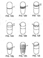
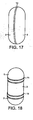
- the cap and body of the capsule are of mutually similar, cylinder-like shape, consisting of a self-contained shell, each with a closed and an open side.
- the shape and size of the cap and the capsule are such that the body can be telescoped with its open end into the open end of the cap in that the cap is firmly connected to the body.
- the cap and body are in the shape of a round cross-section cylinder with a convex, near-hemispherical closed bottom and are both made of high-density polyethylene having a density between 950 and 1000 kg / m 3 .
- the cap and body are provided with closure means which are advantageous in the temporary and / or final closure of the capsule.
- closure means may be on the inner surface of the cap punctiform projections and on the outer surface of the body slightly larger punctiform depressions, which are arranged so that when closing the capsule, the elevations engage in the recesses.
- the protrusions on the outer shell of the body and the recesses may be formed on the inner surface of the cap. Preference is given to arrangements in which the elevations or depressions are respectively arranged in a ring or spiral around the shell. Instead of the punctiform design of the elevations and depressions, these can also continuously encircle the jacket of the cap or of the body in an annular manner. Longer detents are preferred.
- one or more annularly extending elevations are formed such that in the closed state of the capsule, a survey of the cap is in each case adjacent to a survey of the body. In the embodiments with said annular depressions and / or elevations, these may be continuous or interrupted.
- protrusions are formed on the outside of the body near the open end, and holes are formed in the cap near the open end so that the protrusions of the body in the closed state of the capsule engage in the holes of the cap.
- the surveys can be such that the cap can be opened at any time without damaging the capsule or that the capsule can not be opened without destruction after a single closure.
- capsules with at least two such latching possibilities which fix the two capsule parts to different degrees.
- a first latching possibility may be formed near the openings of the capsule cap and the capsule body and a second offset somewhat further to the closed end of the capsule parts. The first latching possibility fixes the two capsule parts less strongly than the second.
- This variant has the advantage that the capsule cap and the capsule body can first be preliminarily connected to one another via the first latching mechanism prior to filling. To fill the capsule then the two capsule parts are separated again After filling, the two capsule parts are plugged together until the second set of detents fixed the capsule parts.
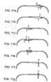
- a bead is formed on the outside of the body, which runs perpendicular to the connecting axis between the cap and body around the body.
- the bead serves as a stopper for the capsule when it is placed over the body to prevent the cap from piercing the body.
- the area between the open end of the body and the bead corresponds to the area of the body over which the cap can be pushed.
- the bead is located on the body so that the cap can be pushed far enough over the body to effect a tight closure between the cap and the body. This means that the bead is not located directly on the open side of the body, for example.
- the side of the bead which points to the open end of the body, stands as a vertical edge so on the outer wall of the body that the Cap can not be pushed over the bead when closing.
- the side of the bead facing the closed end of the body may be in the form of a nearly rectangular edge or flattened towards the closed end of the body.
- the formation of a nearly right-angled edge can be advantageous in the case of loose fitting of the capsule in a capsule holder, the variant with flattening bead in a fixed fit.
- the bead can be continuous or interrupted.
- the bead flattens continuously towards the closed end of the body and is perpendicular to the capsule body with its side oriented toward the open end of the body.
- the height of the edge thus formed is such that the edge does not protrude beyond the capsule cap in the closed state of the capsule, so that the transition from capsule cap to capsule body is stepless.
- the diameter of the capsule body may be suddenly reduced in size at one point, so that the opening-oriented diameter is smaller (or larger) than the diameter oriented toward the closed end of the body.
- the cap and body can be designed so that the capsule is stepless in the closed state at the interface.
- the shape of the wall of the cap in the opening area is formed exactly the reverse of the shape of the wall of the opening of the capsule. That the wall of the cap widened in the region of the opening to form an inner edge.
- the outer sheath is preferably flat. In this embodiment, the cap is placed on the capsule until the edge of the cap and the edge of the capsule touch.
- the bead is located on the inside of the capsule body.
- the capsule cap is not attached to the capsule body, but inserted into the capsule body.
- the cap and body can be designed so that the capsule is stepless in the closed state at the interface.
- the two attachment possibilities of the capsule cap over or into the capsule body are described as equivalent, ie if one of the two variants is described, the same applies to the other variant.
- the edge of the capsule body is formed as a U-shaped circulation, in which the edge of the opening of the capsule cap is inserted.
- both openings on such Ufömigen circulation are provided.
- the edge of the openings of the cap and the body is widened and infinitely formed facing the opening
- the thickness of the walls of the cap and body can vary over the entire range.
- the wall thickness is generally greater in the rounded areas of the cap or body or at the location of the body where the bead is formed than in the areas where the walls are rectilinear.
- the walls of the cap and the body have a thickness of 0.1 mm to 0.5 mm, preferably, the capsule has an average wall thickness of 0.1 mm to 0.4 mm, particularly preferably 0.2 mm to 0th , 4 mm up.
- the capsule body has in the region of its opening, in particular at its edge, a thickness of 0.15 mm to 0.35 mm, preferably 0.225 mm to 0.275 mm, particularly preferably 0.25 mm.
- the capsule cap has in the region of its opening, in particular at its edge, a thickness of 0.25 mm to 0.45 mm, preferably 0.325 mm to 0.375 mm, particularly preferably 0.35 mm.
- the length of the capsule is 8 mm to 30 mm, preferably 13 to 17 mm, particularly preferably 15.5 mm to 16 mm.
- the diameter of the capsule is 4 mm to 7 mm, preferably 5.3 mm to 6.3 mm. Particularly preferred 5.75 to 5.95 mm.
- a preferred capsule has a length of 15.9 mm, a diameter of the capsule body of 5.57 mm and a diameter of the capsule cap of 5.83 mm.
- the preferred wall thickness of the capsule body is 0.25 mm and that of the capsule cap 0.35 mm.
- nubs are formed on the outside of the capsule, in another three or more ribs which run parallel to the longitudinal axis of the capsule.
- the advantage of these devices is that the capsule can be taken out of a capsule holder, such as those used in the above-mentioned powder inhalers, so that it is not damaged or rises.
- the ribs or nubs may extend over the entire outside of the capsule or cover only a portion of it. Alternatively, they may be formed only on the cap or only in the region of the body which is visible in the closed state to the outside.
- the ribs are parallel to the longitudinal axis of the capsule and cause the capsule to be fixed vertically in said capsule holder.
- the ribs are preferably arranged so that the cross section of the capsule does not have rotational symmetry about the central axis.
- the ribs may be formed only in the region of the body that is visible in the closed state of the capsule. Such an embodiment prevents the capsule from being clamped in a capsule holder.
- the Ribs are formed so that the ends of the ribs oriented towards the open end of the body fulfill the function of the bead, namely to serve as a stopper for the cap when the cap is joined to the body.
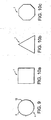
- the shells of the cap and the body describe a hollow cylinder with round, oval, three, four, six, eight or polygonal cross-section, the respective top being open and the bottom being closed.
- the closed bottom can be flat or convex.
- the angular embodiments have e.g. the advantage that they can be stored space-saving than the round.
- the elongation of the capsule is greater than 1, in one embodiment the elongation is equal to 1 and in yet another embodiment the elongation is less than 1
- the body has a larger opening for filling.
- the cap and body are such that the closed capsule is in the form of a sphere, which may be advantageous for automatically loading a powder inhaler with the capsule from a reservoir.
- the capsule is particularly suitable for containing any powdered and inhalable pharmaceutical formulation.
- the capsule contains cromoglicin, reproterol, beclomethasone, terbutaline, salbutamol, salmeterol, ketotifen, orciprenaline fluticasone, insulin, lpratropium, tiotropium, dexamethasone, bambuterol, tiotropium, budesonide, fenoterol, clenbuterol prednisolone, prednisone, prednylidene, methylprednisolone , Formoterol, nedocromil, their pharmacologically acceptable salts or mixtures or other suitable for inhalation cortisone preparation or atropine derivative.
- the capsule contains ipratropium bromide or tiotropium bromide.
- the sealed capsules can absorb liquids as well as powder fillings and are then also suitable for novel liquid inhalers.
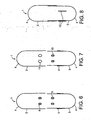
- For the cohesive closing of the at least two telescopically insertable sub-elements of the capsule is particularly a method in which a locally narrow energy beam of hot gas or laser light is guided in a relative movement at least once completely around the vertical axis of the overlapping portion of the capsule elements, so that the capsule material in this area is melted, but not destroyed and a cohesive seam is formed on this area.
- the rotational movement can be effected either by the fact that the capsule rotates about its axis, which is perpendicular to the plane of the weld in the energy beam or the energy beam is guided around the capsule.
- the capsular seam is then welded within one revolution or several turns.
- Hot gas and laser light are preferably used as energy sources in the process according to the invention.
- laser light is induced in the capsule material necessary for the welding thermal energy by absorption.
- the welding itself can take place either directly at the interface of the two capsule parts or in the overlapping part of the two capsule halves.
- the resulting weld is formed as one or more closed line (s) along the capsule periphery parallel to and between the two planes that span the openings of the cap and body.
- weld In addition to self-contained lines as. Weld, spiral lines are possible.
- shape of the welds is not limited to rectilinear shapes, but may also be performed jagged meandering or in any other form around the capsule shell.
- the weld can also be performed as a spot weld.
- the weld is formed at a position where the capsule body and capsule cap just start to overlap.
- several welds can be applied. These can for example be formed parallel to each other.
- the position of the welds can be selected centrally to the longitudinal axis. Is preferred However, an asymmetric position to allow the greatest possible distance to the capsule filling.
- the term length is understood to mean the distance between the opening of each of the two capsule halves and the opposite closed side.
- the seam is preferably located in the upper third of the closed capsule. That is, the portion of the capsule body from the closed bottom to the place of formation of the bead described above, which marks the point to which the open end of the capsule cap is placed over the opening of the capsule body on the latter, about 2/3 of the total length the closed capsule is.
- Such a capsule has the advantage that the filling level of the formulation within the capsule can be below the interface, so that the risk of reducing the quality of the formulation by the welding process is significantly reduced.
- the filling height of the capsule can be adjusted according to the welding temperature and the temperature sensitivity of the pharmaceutical formulation.
- the present invention therefore also allows the production of such a plastic capsule with asymmetrical position of the weld.
- the other characteristics of the capsule have been described in detail at the beginning.
- the use of a measuring device allows the assessment of the welding temperature and the flow behavior of the capsule material during the welding process and thus a targeted control.
- the welding process preferably takes place in feedback with the data from the measuring device in order to achieve a consistently high quality of the weld. As a result, a uniform energy input at the weld can be obtained.
- the feedback is similar to fluctuations e.g. the material thickness and environmental influences by either the rotational speed of the relative rotation or the supplied energy is readjusted.
- the energy supplied and the relative rotational speed are preferably matched to one another so that the capsule material is just being melted.
- the energy beam, its distance to the capsule surface and its average residence time on the capsule surface are adjusted so that the capsule material is melted without a hole being burned into the capsule wall.
- the rotational speed of the energy beam around the capsule or the capsule in the energy beam can be between 0.01 revolutions per second and a maximum of 40 revolutions per second. In the case of laser welding, it may preferably be 0.1 to 20 revolutions per second, in the case of hot gas welding, preferably 0.2 to 2 revolutions per second.
- the peripheral speed of the preferred capsule with a length of 15.9 mm and a diameter of the capsule cap of 5.83 mm and a diameter of the capsule body 5.57 mm from about 0.18 mm per second up to 732 mm per second ,
- the peripheral speed is preferably 1.8 mm per second to 366 mm per second, and in the case of hot gas welding, 3.7 mm per second to 37 mm per second.
- the number of revolutions capsule / energy beam can be up to 40, preferably up to 20 for a welding operation. In the case of the laser welding method, it is preferably 2 to 3, in the case of hot gas welding 5 to 8.
- the capsules and the energy source are preferably brought together at a certain feed rate.
- feed rates of 0.1 cm per second to 10 cm per second, more preferably 1 cm per second to 5 cm per second.
- the capsules can be welded with a cycle time of preferably less than 10 seconds. More preferred are methods in which the capsule is sealed within 5 seconds, more preferably within 1 second.
- the last criterion is limited to cylindrical capsules with respect to the longitudinal axis of the central weld. Particularly preferred are rotationally symmetrical capsules.
- the circumference of the capsules is circular.
- the circumference can also be polygonal or elliptical.
- the externally preferred shape of the capsule has no steps. Particularly preferred are plastic capsules according to the published patent application DE 198 35 346 A1.
- the capsule sutures are either unfocussed at a medium working distance with a medium dose, or preferably with active jet control, focusing in accordance with the capsule geometry synchronously with rotation, or, most preferably with an intensity control that compensates for a defocusing by power increase.
- the advantage of the dyes in the plastic is that the colors absorb the laser light in the plastic and thereby locally heat the plastic to the extent that it comes to a weld.
- the used dyes are adjusted to the frequency of the laser light and the required amount of heat.
- Dyes chosen are dyes which do not alter the pharmaceutical grade of the formulation in the capsule. Preferably, food colors are used.
- the inorganic pigments are particularly preferred.
- the aggregates may either be applied to the finished capsule parts (e.g., by spraying, printing, brushing, dipping) and then melted in the welding process, or they may be used in the manufacture of the capsules e.g. incorporated in the capsule material in a masterbatch process.
- the periphery In laser welding, the periphery must be fully irradiated for complete sealing of the entire capsule periphery. It is possible a line optics, which simultaneously welded the entire circumference is preferred relative movement of capsule and light beam and the associated leadership of the focal spot along the capsule circumference. For example, this can be done by rotation of the capsule in the light beam of the laser.
- the laser beam can be guided around the capsule by means of rotating mirrors.
- the relative rotation of capsule and laser beam by means of a holder which allows synchronization between rotational angle and laser activity.
- a radiation measuring device is preferably used in laser welding.
- the feedback compensates for variations in material thickness, reflectivity, focusing and other environmental influences by adjusting either the rotational speed or preferably the laser power.
- the smallest possible spot of the suture is preferably melted under temperature or radiation measurement.
- the laser power required for welding depends on the optics chosen (size of the focal spot), on the feed rate, on the surface finish of the material (eg roughness), the optical properties of the material (eg transparency) and the necessary melting temperature of the material.
- green-colored plastic capsules were welded with a 5-watt argon ion laser beam (wavelength all line, 514 nm and 488 nm), focusing with a microscope objective (magnification 10X).
- the same capsules could also be welded with an infrared laser (wavelength around 900 nm) with a beam power of about 100 watts
- the weld seam can be formed both immediately and only on the second or even later, repeated irradiation.
- the capsule and light source are preferably rotated relative to each other so that the once irradiated point is not yet cooled again when it hits the laser beam again.
- the focus of the laser beam is preferably selected to be just so high that only little heat is generated on the inside of the capsule wall and localized on the seam of the capsule.
- the width of the weld can be adjusted by rapid oscillatory movement of the focal spot in directions other than the welding feed direction.
- the width adjustment by optical imaging of the laser radiation to a focal spot, preferably of less than 1 mm.
- a focal spot diameter is particularly preferred.
- one (or two) long slotted nozzle (s) should be used, on which (at which) several capsules are passed at once with continuous rotation.
- crescent-shaped slot dies can be advantageously used when the method is such that the capsules are rotated in the heat beam.
- the dimensions of the slots of the nozzle are chosen so that with respect to the height of a very narrow heat beam.
- the height of the slot opening is preferably up to 3 mm, preferably up to 2 mm, particularly preferably up to 1 mm.
- the length of the opening is variable. In the case of non-radial welds, the length should also be limited, like the height, to 3 mm, preferably 2 mm, particularly preferably 1 mm. In the case of welds extending radially or spirally around the capsule, the length of the nozzle slot is of minor importance
- the height of the weld is determined by the height of the jet.
- the region of the capsule on which the weld is to be formed is guided parallel to the longitudinal side of the nozzle arrangement in the energy beam.
- the length of the nozzle order and the temperature of the energy beam, together with the melting range of the capsule material, determine the residence time of the capsule in the energy beam. That is, the longer the nozzle opening and the hotter the energy beam, the faster the capsule must be parallel to this Direction to be turned. That is, the weld around the capsule is formed parallel to the length of the nozzle order.
- the length of the slot nozzle can be many cm or even in the meter range.
- Such an elongated slot nozzle is particularly advantageous if several capsules are to be provided in a continuous flow band manner with a weld seam.
- the inventive method is preferably controlled so that the weld does not occur immediately, but only at the second or even later, repeated blowing hot gas.
- the repetition is preferably carried out by rotation of capsule and hot gas nozzle relative to each other, before the blown point is cooled again.
- the temperature of the gas required for welding depends on the melting ranges of the plastics used and their distance from the hot gas nozzle. However, in order to apply as narrow a hot gas jet as possible to the seam, the capsule is guided very close to the nozzle. Preferably at a distance of 5 mm.
- the width of the hot gas jet at the weld is 1 mm to 2 mm.
- the capsule holder required for carrying out the method according to the invention consists of two separate molds, the interior design of which is dish-shaped.
- the shell mold is in each case designed so that one of the capsule body receives a conclusive, the other the capsule cap, wherein in the closed state only remains to be welded seam area of the holder uncovered.
- the advantage of this measure is that only the area of the capsule to be welded can come into contact with the energy beam and the other areas of the capsule are protected from the beam.
- up to 3 mm are left free by the edge of the respective capsule halves to be formed as a seam, very particularly preferably 0.5 mm to 1 mm.
- the outer design of the holder is not critical, but should allow the outflow of the hot gas.
- the two support parts may be cylindrical in shape.
- the upper part and the lower part of the capsule holder are coupled so that the position of the workpieces is held even with fused connection between the items, without exposing the capsule of a torsion or tension This is particularly important for the welding process, when the dimensional stability of the capsule by heating a Subarea is reduced.
- the task of the capsule holder is to hold the capsule and bring it close to the power source for the welding process. At the same time, they serve to cool the areas of the capsule walls which are not to be welded and thus also protect the formulation in the capsule.
- the filling height of the capsule is preferably below the weld, in the protected area.
- the capsule holder may be configured to cool the capsule.
- systems with water cooling or Peltier elements are suitable for this.
- At least a part of the two halves of the capsule holder is connected to a rotating device, so that the capsule can be rotated about the energy source.
- the capsule holder itself rotates about its own axis, which is spanned by the upper part and lower part of the holder.
- a plurality of capsule holders may be arranged on a conveyor device, for example, and preferably in series.
- the holder for the capsule body is connected to a conveying device.
- a second a second winningvircardi at which the holder for the capsule cap is mounted so that in each case a capsule with her body in the holder provided for this purpose and the capsule cap in the holder provided for them.
- the conveying devices are such that the two halves of the capsule holders can be separated after welding, so that the capsules remain only in one of the two halves, preferably that for the original capsule body. This can e.g. happen that the conveyors are each conveyor belts that diverge diverging after the site of welding initially within the same plane. Thereafter, the capsules can be removed from the holder.
- the brackets may be secured to the conveyor via a telescopically extendable arm. These arms are extended in the direction of the other arm when the capsule is welded, so that the capsule is protected by the two antipodes of the holder in the manner described above. After the welding process, the arms pull together again, so that the two halves of the bracket are moved apart.
- the capsules can be brought to the energy source.
- the brackets are rotatably mounted on the conveyor about itself.
- the capsule holder as a whole rotates around itself, thereby rotating the capsule in the energy beam so that the weld is formed around the capsule.
- the energy beam can be performed according to the capsule.
- the capsule holder according to the invention advantageously leads to a remedy also with respect to this source of danger.
- the capsule holder also protects the capsule parts that are not to be welded and the formulation in the capsule.
- the advantage of the capsules produced according to the invention is that they have a very low water vapor permeability, in particular at the interface and thereby also in the different climatic zones, for example in the climatic zone 3 can be used with high humidity without the pharmaceutical quality of the formulation suffers .
- These capsules also have several advantages over other stages of life of the capsule from manufacture to use the usefulness of the capsule as a carrier of pharmaceutical preparations, the mode of administration of the ingredients, the shelf life of the ingredients and / or the usability of the capsule in certain countries.
- a further advantage of the capsule materials according to the invention consists, for example, in the fact that they tend not to bind powdery substances to themselves, so that an exact metering of the respirable fine fraction is facilitated.
- These capsules can also be used in non-medical aerosols.
- FIG. 2 a shows in cross-section an embodiment in which a bead 5 is formed on the body 3 of the capsule 1 and tapers towards the closed end of the body. With the side oriented toward the open end of the body, the bead 5 stands almost perpendicular to the body. The thus formed edge limits the area of the body over which the cap 2 can be telescoped.
- FIG. 2b Another embodiment is shown in FIG. 2b.
- the cross section shows that this embodiment differs from that shown in Figure 2a in that the wall thickness of the cap 2 and the body 3 is not the same extent over the entire area, but varies over individual subregions.
- the convex undersides 4 of the cap or the body each have a concave indentation at the apex.
- FIG. 3 shows an embodiment in which the bead 5 rests on the body almost at right angles both to the upper side of the body and to its underside.
- the embodiment of Figure 4 illustrates a further development of the embodiment of Figure 2a, in which an annular recess 6 or 7 is formed in cap 2 or body 3 for better closure of the capsule 1 .
- FIG. 5 shows a front view of the embodiment shown as a cross section in FIG.
- FIG. 6 shows a further variant of FIG. Invention with punctiform depressions 8 and 9 as a frontal view.
- Figure 7 a variant of the capsule 1 is shown, in which the body 3 near the open end elevations 10 and in the cap 2 near the open end holes 11 are formed so that the elevations 10 engage in closing the capsule in the holes 11 , 8 shows an embodiment of the capsule 1 from the outside, in which on the Body 3, the ribs 12 are formed.
- FIG. 9 shows the body 3 of the embodiment of FIG. 7 in cross section. The cross section shows that the three ribs 12 are not arranged rotationally symmetrical about the central axis of the body.
- FIG. 10 a shows a capsule 1 with a quadrangular cross-section, one with a triangular cross section in FIG. 10 b and one with an octagonal cross-section in FIG. 10 c.
- FIGS. 11 a - g show various embodiments of capsules 1 with non-centrally located closure point between the cap and the body for forming the weld seam 13 .
- Fig. 11a shows a shutter wherein on the outside of the body an inwardly offset edge (5) is formed and on the inside of the cap an outwardly directed edge (5). The connection is reinforced by a catch, preferably two notches.
- Fig. 11b shows an embodiment in which only the body has an inwardly offset edge (5). Cap and body complete steplessly against each other.
- Fig. 11a shows a capsule 1 with a quadrangular cross-section, one with a triangular cross section in FIG. 10 b and one with an octagonal cross-section in FIG. 10 c.
- FIG. 11c shows an embodiment in which only on the cap an inwardly offset edge (5) is formed. The body does not have this feature. Cap and body complete steplessly against each other.
- Fig. 11d shows an analogous embodiment in which in the overlapping area of cap and body one or more dimples and one or more mating recess (s) on the counterpart are formed to provide a better preliminary closure prior to welding to reach.
- Fig. 11 e has an embodiment in which the closure is such that the body no Closure features, the cap has at its open end a U-shaped circulation (21) which can be plugged onto the open edge of the body wall.
- Figures 11f and g have embodiments in which the thickness of the walls thicken the open ends (22) of the body and cap to achieve a wider contact zone in the closure region between the two capsule halves.
- Figures 12a-i show capsules 1 with different shapes of weld 13 : a) c) and d) rectilinear, e) spot welds, f) zigzag, g) and h) parallel diagonal non-continuous welds, b), i) spiral.
- FIG. 13 shows a capsule holder 14 consisting of the holder 15 for the capsule body 3 and the holder 16 for the capsule cap 2 .
- FIG. 14 shows a capsule holder 14 in the energy beam 18 of a laser 17 .
- FIG. 15 shows a capsule holder 14 with a capsule 1 , around which the laser beam 18 is guided by means of two mirrors 19 .
- FIG. 16 shows a capsule holder 14 in the energy jet of a hot gas nozzle 20 . The nozzle can also be made wider, so that at the same time several capsules can be passed in series on the slot-shaped nozzle.
- Fig. 17 shows a capsule in which the interface between the cap 2 and body 3 is formed perpendicular to the longitudinal axis of the capsule.
- Fig. 18 shows a capsule consisting of two caps 2 and a body 3. In this case, the body is a pipe open on two sides, each opening being closed by a respective cap 2 .
- the cap and body features described for sealing the capsule may also be reciprocal, ie, closure features located on the cap may be formed on the body and vice versa.
- Steinel hot air blower 1800 W electronically controlled.
- the operating data are specified by the respective laser. Achieved 0.75 seconds per capsule with about 30 watts of light output.
- the average residence time of a weld in the case of laser welding at a focal spot of 0.1 mm diameter, when the capsule performs 2 revolutions within 8 seconds, which corresponds to a peripheral speed of 4.6 mm per second, is approximately 22 milliseconds.
- a capsule with a length of 15.9 mm, a diameter of the capsule body of 5.57 mm and a diameter of the capsule cap of 5.83 mm was used, the wall thickness of the capsule body was 0.25 mm and that of the capsule cap 0.35 mm.
- the average residence time is about 0.26 seconds when using a hot air jet about 1 mm high and 7 mm wide, and the capsule is rotated 12 times in the jet within 8 seconds. The speed at the capsule circumference is then about 27 mm per second.
- Length of the capsule body 22.2 ⁇ 0.46 mm; 20.22 ⁇ 0.46 mm; 20.98 ⁇ 0.46 mm; 18.4 ⁇ 0.46 mm; 16.61 ⁇ 0.46 mm; 15.27 ⁇ 0.46 mm; 13.59 ⁇ 0.46 mm; 12.19 ⁇ 0.46 mm; 9.3 ⁇ 0.46 mm.
- Length of the capsule cap 12.95 ⁇ 0.46 mm; 11.74 ⁇ 0.46 mm; 11.99 ⁇ 0.46 mm; 10.72 ⁇ 0.46 mm; 9.78 ⁇ 0.46 mm; 8.94 ⁇ 0.46 mm; 8.08 ⁇ 0.46 mm; 7.21 ⁇ 0.46 mm; 6.2 ⁇ 0.46 mm.
- Outer diameter of the capsule body 9.55 mm; 8.18 mm; 7.36 mm; 7.34 mm; 6.63 mm; 6.07 mm; 5.57 mm; 5.05 mm; 4.68 mm.
- Outer diameter of the capsule caps 9,91 mm; 8.53 mm; 07,66mm; 7.64 mm; 6.91 mm; 6.35 mm; 5.83 mm; 5.32 mm; 4.91 mm.
- Total length of closed capsule 26.1 ⁇ 0.3 mm; 23.3 ⁇ 0.3 mm; 24.2 ⁇ 0.3 mm; 21.7 ⁇ 0.3 mm; 19.4 ⁇ 0.3 mm; 18.0 ⁇ 0.3 mm; 15.9 ⁇ 0.3 mm; 14, ⁇ 0.3 mm; 11.1 ⁇ 0.3 mm.
- Weight of the capsules 163 mg; 118 mg; 110 mg; 96 mg; 76 mg; 61 mg; 48 mg; 38 mg; 28 mg.
Landscapes
- Engineering & Computer Science (AREA)
- Mechanical Engineering (AREA)
- Physics & Mathematics (AREA)
- Health & Medical Sciences (AREA)
- Thermal Sciences (AREA)
- Electromagnetism (AREA)
- Toxicology (AREA)
- Optics & Photonics (AREA)
- Chemical & Material Sciences (AREA)
- Life Sciences & Earth Sciences (AREA)
- Animal Behavior & Ethology (AREA)
- General Health & Medical Sciences (AREA)
- Public Health (AREA)
- Veterinary Medicine (AREA)
- Medicinal Chemistry (AREA)
- Pharmacology & Pharmacy (AREA)
- Combustion & Propulsion (AREA)
- Bioinformatics & Cheminformatics (AREA)
- Pulmonology (AREA)
- Anesthesiology (AREA)
- Biomedical Technology (AREA)
- Heart & Thoracic Surgery (AREA)
- Hematology (AREA)
- Medical Preparation Storing Or Oral Administration Devices (AREA)
- Lining Or Joining Of Plastics Or The Like (AREA)
- Medicinal Preparation (AREA)
Description
- Die vorliegende Erfindung betrifft ein neues Verfahren zum Verschweißen von Kunststoffkapseln für Inhalatoren, sowie einer Vorrichtung die speziell daran angepasst ist, das erfindungsgemäße Verfahren auszuführen. Die durch das erfindungsgemäße Verfahren hergestellten Kapseln sind Einweg-Kapseln und enthalten bevorzugt eine Einzeldosis einer inhalativ applizierbaren pharmazeutischen Formulierung in Form eines Pulvers oder einer Flüssigkeit und sind von der Form und Funktion geeignet zur Verwendung in Pulverinhalatoren oder Flüssigkeitsverneblern zur Erzeugung von Aerosolen. Solche erzeugten Aerosole können beispielsweise inhaliert werden, so daß eine pharmazeutische Formulierung pulmonal appliziert wird.
- Kapseln mit pharmazeutischen Zubereitungen werden vielfältig in der Therapie und Diagnose von Krankheiten eingesetzt. Die Kapseln können oral verabreicht werden oder kommen in bestimmten medizinischen Vorrichtungen, wie Pulverinhalatoren, zum Einsatz. In der Regel bestehen die Kapseln aus zwei Teilen, einem Kapselkörper (Körper) und einer Kapselkappe (Kappe), die teleskopartig ineinander geschoben werden. Aber auch mehrteilige Kapseln sind bekannt. Die Kapseln bestehen meistens aus Gelatine, insbesondere Hartgelatine. Für einige spezielle Anwendungen bestehen die Kapseln zuweilen auch aus für den Menschen gut verdaulichen, wasserlöslichen Kunststoffen, um bei oraler Verabreichung den Wirkstoff in bestimmten Kompartimenten des Magen-Darm-Trakts freizusetzen. Im folgenden sind Beispiele für verschiedene Kapselmaterialien aufgeführt.
- EP 0460921 beschreibt Kapseln aus Chitosan und Stärke, Getreidepulver, Oligosacchariden, Methacrylsäure-Methylacrylat, Methacrylsäure-Ethylacrylat, Hydroxypropylmethyl-Celluloseacetat, -succinat oder -phthalat.
- Das Kapselmaterial zeichnet sich dadurch aus, daß der Inhalt erst im Dickdarm freigesetzt wird.
- GB 938828 offenbart Kapseln für radioaktive Substanzen im therapeutischen oder diagnostischen Einsatz. Die Kapseln bestehen aus wasserlöslicher Gelatine, Methylcellulose, Polyvinylalkohol oder wasserlöslichen nichttoxischen Thermoplasten.
- Die EP0312760 beschreibt ein Verfahren zum Versiegeln von Hartgelatine oder Stärkekapseln mit einem bestimmten Siegelmittel. Die Naht der Kapseln kann dabei von der Mittelebene der Längsachse der Kapsel verschoben sein.
- Die DE 3430764 offenbart ein anderes Verfahren zum Verschließen von Hartgelatinekapseln. Bei dem Verfahren werden die Kapseln zunächst gefüllt und die beiden Kapselhälften teleskopartig ineinander gesteckt. Anschließend wird durch Anheben der Kapselkappe gegenüber dem Kapselkörper am Kapselkörper eine Kontaktzone freigelegt, wobei die Kapsel nicht geöffnet werden darf. In einem nächsten Schritt wird dann die Kontaktzone "klebrig" gemacht um anschließend wird die Kapselkappe wieder zurück auf ihren ursprünglichen Position geschoben und dabei mit der Kontaktzone in Berührung gebracht. Dieses Verfahren erfordert eine hohe Präzession bei der Ausführung, insbesondere da vermieden werden muss, die Kapsel beim Zurückführen der Kapselkappe auf den durch Erwärmung klebrig gemachte und damit gegenüber Verformung anfälligen Kapselkörper zu verformen. Auf Seite 32 der Anmeldung wird davon gesprochen, dass zum Halten und Führen der Kapselteile Werkzeuge notwendig sind, die keinerlei Toleranzen oder Spiel aufweisen.
- Die US 4991377 offenbart ein weiteres Verfahren zum Verschweißen von Keratin- oder Gelatinekapseln. Bei dem Verfahren wird die geschlossene, Kapsel, welche aus zwei teleskopartig verbunden Teilen besteht, an der Nahtstelle mit Heißluft behandelt. Bei dem Verfahren sitzt der untere Bereich der Kapsel auf einem Halter. Die Patentschrift gibt weder einen Hinweis darauf wie eine Verformung der durch den Wärmestrahl erweichten Kapseln vermieden werden kann noch wie ein Erwärmen oder Verkohlen andere Kapselbereiche außerhalb der Nahtzone vermieden werden kann. Es wird auch nicht offenbart, wie die Inhaltsstoffe in der Kapsel vor der durch das Verschweißen bedingten Hitze in seine Qualität beeinträchtigt wird.
- Die WO 00/07572 offenbart Kapseln für Inhalatoren der erfindungsgemäßen Art, welche aus nicht-verdaulichem Kunststoff bestehen. Die dort beschriebenen Kapseln werden analog den handelsüblichen Hartgelatinekapseln verschlossen, das heißt die Kapselkappe wird teleskopartig auf den Kapselkörper aufgesteckt. Gegebenenfalls kann die dabei zwangsläufig entstehende Naht zwischen Kapselkappe und Kapselkörper verschweißt, verklebt oder banderoliert werden, um die Wasserdampfpermeabilität zu reduzieren. Alternativ kann die gesamte Kappe mit einem durchgehenden Schutzfilm überzogen werden oder der Spalt der Nahtstelle wird mit einem Füllstoff verschlossen. Einzelheiten zu den Verfahren zum Verschließen der Kappe werden nicht offenbart, insbesondere keine Schweißverfahren.
- Zum Verschweißen von Kunststoffmaterialien sind aus dem Stand der Technik verschiedene thermische Verschweißungsarten bekannt. Dazu zählen Ultraschallverschweißen, Heißplatten- und Heiß-Werkzeug-Verschweißen, Heißgasverschweißen, Drehschweißen, Hoch-Frequenz-Spannungs-Verschweißen oder Induktionsschweißen.
- Nicht bekannt dagegen sind derartige Verfahren zum Verschließen von Kunststoffkapseln für medizinische Inhalatoren, die bezüglich der Verwendung bestimmten Rahmenbedingungen unterworfen sind.
- Es hat sich nun gezeigt, daß sich diese Schweißverfahren nicht ohne weiteres auf das Verschweißen der in der WO 00/07572 beschriebenen Kapselhälften übertragen lassen.
- Zu den oben genannten Rahmenbedingungen, die einem einfachen Übertragen der aus dem Stand der Technik bekannten Verfahren auf Inhalationskapseln entgegenstehen, zählt beispielsweise, daß die Kapseln mit einer pharmazeutischen Formulierung gefüllt sind, deren pharmazeutische Qualität während des Verschweißens nicht vermindert werden darf.
- Eine weitere Rahmenbedingung stellt die Abmessung und Wandstärke der zu verschweißenden Kapseln dar, insbesondere die dünne Wandung einer solchen Kapsel. Diese ist notwendig, da die Kapsel analog den bisher gebräuchlichen Hartgelatinekapseln in einem handelsüblichen Inhalator verwendet werden können soll. Dort muß sie nämlich in einfacher Art und Weise geöffnet werden. Werden die herkömmlichen Verfahren auf eine solche Kapsel angewandt, kommt es beispielsweise schnell zum Einbrennen von Löchern während des Verschweißens, besonders in den Bereichen der Kapsel, die außerhalb des Bereichs liegen, der verschweißt werden soll. Dieser Bereich, an dem die Nahtstelle ausbildet werden soll befindet sich naturgemäß ein einem Bereich, in dem die Wandungen der beiden miteinander zu verbindenden Teile überlappen. Daneben gibt es Bereiche, bei denen keine derartige Überlappung vorliegt. In diesen Bereichen kann die Kapsel durch den Schweißvorgang leichter beschädigt werden. Daneben besteht auch die Gefahr, daß bei zu dicken Kapselwandungen eine Schweißnaht an der Nahtstelle nicht durchgehend ausgebildet wird.
- Mit der vorliegenden Erfindung sollen dichte Kunststoffkapseln für medizinische Inhalationsgeräte geschaffen werden, die eine pharmazeutische Formulierung enthalten. Bevorzugt enthalten diese Kapseln eine Einmaldosis der Formulierung. Die Kapseln werden im Kontext der vorliegenden Erfindung auch Einzeldosis-Kapseln genannt.
- Ein für die vorliegenden Zwecke bevorzugter Inhalator wird beispielsweise in der WO 94/28958 beschriebenen (HandiHaler®). Aus der EP-A-0 360 765 ist ein Verfahren zum stoffschlüssigen Verschweißen von Arzneimittel enthaltenden, aus Kapselkörper und Kapselkappe bestehen der Kapsel bekannt, bei dem der Kapselkörper von einem Kapselhalter gehalten wind, ohne den überlappenden Bereich von Kapselkappe und Kapselkörper zu bedecken, und mittels eines Energiestrahls aus Heißgas in einer Relativbewegung zur Kapsel im überlappenden Bereich eine stoffschlüssige Nahtstelle gebildet wird.
- Damit besteht eine Aufgabe der Erfindung darin, ein Schweißverfahren und eine speziell daren angepasste Vorrichtung zu schaffen, bei dem die Bereiche einer Kunststoffkapsel, die nicht verschweißt werden sollen, nicht bis zum Schmelzbereich des Kunststoffs erwärmt werden.
- Eine weitere Aufgabe besteht darin, eine Schweißverfahren für Kunststoffkapseln zu schaffen, bei dem die einzelnen Teile einer solchen Kunststoffkapsel für Inhalatoren fest zusammengehalten werden.
- Eine weitere Aufgabe besteht darin, die einzelnen Teile einer Kunststoffkapsel so miteinander zu verbinden, dass sie ohne Beschädigung der Kapsel nicht mehr getrennt werden können. Dies erleichtert dem Verwender festzustellen, dass die Kapsel zuvor nicht bereits geöffnet wurde.
- Eine weitere Aufgabe besteht darin, ein Schweißverfahren für Kunststoffkapseln zu schaffen, bei dem es nicht durch den in der Kapsel durch das Verschweißen erzeugten Überdruck zu einer Beschädigung der Kapsel kommt bzw. in dem ein solcher Überdruck minimiert wird.
- Eine weitere Aufgabe besteht darin, Schweißverfahren für Kunststoffkapseln zu schaffen, bei dem die pharmazeutische Qualität der Arzneimittelformulierung in der Kapsel, die erfindungsgemäß eine Inhalationsformulierung ist, während des Verschweißens nicht gefährdet ist.
- Eine weitere Aufgabe der Erfindung besteht darin, die Nahtstelle von Inhalationskapseln der vorstehend beschriebenen Art in industriellem Maßstab unter GMP-Bedingungen (Good manufacturing practice) zu verschweißen.
- Die vorliegende Erfindung löst die oben beschriebenen Aufgaben durch ein Verfahren gemäß Anspruch 1 und eine Vorrichtung gemäß Anspruch 25.
- Somit wird gewährleistet, daß ausschließlich der zu verschweißende Bereich einer lnhalationskapsel mittels eines Energiestrahls in Form eines Heißgasstrahls oder eines Laserstrahls verschweißt wird. Dabei kommt es bevorzugt nur an der Nahtstelle zu einer Erwärmung des Kapselmaterials.
- Die zu verschweißenden Kapseln bestehen aus nicht-wasserlöslichen, bevorzugt hydrophoben Kunststoffen, die die pharmazeutische Qualität der Inhaltsstoffe selbst nicht wesentlich beeinflussen, aber die Einsatzfähigkeit der gefüllten Kapsel im Hinblick auf ihre Funktion, die Dauer der Verwendung und/oder die Klimazone verbessern und in verschiedenen Stufen von der Herstellung bis zur Verwendung von Vorteil sind.
- Die Kapsel besteht aus mindestens zwei Teilen, einem Kapselkörper (Körper) und mindestens einer Kapselkappe (Kappe), die so miteinander verbunden werden können, daß ein stabiler, abgeschlossener Hohlraum von definiertem Volumen gebildet wird, der die pharmazeutische Formulierung beinhaltet. Die Dimension der Kapsel ist derart, daß sie in gängigen mit Kapseln bestückten Pulverinhalatoren eingesetzt werden können, wie sie z.B. in den Patentschriften DE 33 45 722 (Inhalator Ingelheim M), EP 0 591 136 (Inhalator Ingelheim) oder in der deutschen Offenlegungsschrift DE 43 18 455 ("HandiHaler®") beschrieben sind. Besonders bevorzugt ist die Kapselgröße 3.
- In einer Ausführungsform ist der Kunststoff der Kapsel für den Menschen nicht verdaubar, so daß bei oraler Einnahme der Wirkstoff nicht freigesetzt wird. Das hat den Vorteil, daß ein versehentliches Schlucken der Kapsel zu keiner nachhaltigen Beeinträchtigung der Gesundheit führen kann. Insbesondere gilt dies für Kleinkinder oder ältere Menschen.
- Bevorzugt werden Kunststoffe verwendet, die spritz- oder blasgußtechnisch verarbeitet werden können und/oder Kunststoffe für deren Verarbeitung zur Kapselkappe oder zum Kapselkörper kein Formtrennmittel notwendig ist, das ein Anhaften der Inhaltsstoffe an die Kapselwand bewirken kann. Das hat den Vorteil, daß das Innere der Kappe oder des Körpers nicht vom Formtrennmittel gereinigt werden muß, um z.B. den amtlichen Bestimmungen (z.B. nach DAB (Deutsches Arzneibuch)) genüge zu tun, die die Verwendung von Formtrennmitteln für Primärpackmittel einschränken. Bevorzugt sind Thermoplaste, die ein stoffschlüssiges Verschweißen der Kapselhälften miteinander ermöglichen
- Bevorzugte Materialien haben die Eigenschaft, daß möglichst wenig, bevorzugt kein Pulver an ihnen haften bleibt.
- Zu den geeigneten Kunststoffen für das erfindungsgemäße Verfahren zählen Polyethylen LD (low density), Polyethylen HD (high densitiy), Polystyrol, Acrylnitril-Butadien-Styrol, Polypropylen, Polymethylmethacrylat, Polyvinylchlorid, Polyoxymethylen, Polycarbonat, Polyester oder Polyethylenterephthalat
- In bevorzugten Ausführungen ist der Kunststoff Polyethylen, insbesondere Polyethylen mit einer Dichte zwischen 900 und 1000 kg/m3, bevorzugt von 960 kg/m3 (high-density Polyethylen).
- In einer bevorzugten Ausführungsform besitzt der Kunststoff keine ausgeprägte Adhäsion für pharmazeutisch-chemische Stoffe, insbesondere für Partikel mit lungengängiger Größe, so daß bei Verwendung der Kapsel in einem der oben beschriebenen Inhalatoren der gesamte Inhalt der Kapsel freigesetzt werden kann. Das hat den Vorteil, daß eine exaktere Dosierung, insbesondere des lungengängigen Feinanteils möglich ist.
- In einer weiteren Ausführungsform besteht die Kapsel aus einem Kunststoff mit einer Shorehärte D von 65 bis 73. Ein Kunststoff dieser Härte zerspringt nicht, wenn er durchstochen oder aufgeschnitten wird, ist aber gleichzeitig starr genug, daß sich das entstandene Loch nicht von selbst verschließt. Der Vorteil eines solchen Materials ist, daß während des Öffnens, Aufstechens oder Aufschneidens der Kapsel im Pulverinhalator keine Teile aus der Kapsel abgesprengt werden, die dann während des Inhalierens eingeatmet werden könnten.
- In einer Ausführungsform ist die Kunststoffkapsel so stabil, daß sie entlang der Längsachse oder der Querachse einer Kraft bis zu 15 N standhält. Der Vorteil besteht darin, daß die Kapsel besser an die Beanspruchungen angepaßt ist, die bei der Herstellung, dem Füllen, Verpacken, Transportieren u.ä. auf die Kapsel einwirken.
- In einer weiteren Ausführungsform besitzt das Material der Kapsel einen Permeationskoeffizienten für Wasserdampf von weniger als 10-13 kg/(ms Pa), bevorzugt weniger als 1,3 x 10⁻¹⁴ kg/(m s Pa). Bevorzugt liegt der Koeffizient zwischen 10-15 und 5 x 10-16 kg/(m s Pa), besonders bevorzugt zwischen 5 x 10-16 und 2 x 10-16 kg/(m s Pa). Der Vorteil dieser Eigenschaft besteht darin, daß die Inhaltsstoffe der Kapsel auch in geographischen Zonen mit hoher Luftfeuchtigkeit vor Wasser geschützt sind.
- Die Kapsel kann in allen Arten von Pulverinhalatoren verwendet werden, bei denen die zu inhalierende Zubereitung durch eine Kapsel eingebracht wird.
In einer bevorzugten Ausführungsform sind Kappe und Körper der Kapsel von gegenseitig ähnlicher, zylinderartiger Form, bestehend aus einem in sich geschlossenen Mantel mit jeweils einer geschlossenen und einer offenen Seite. Dabei sind Form und Größe der Kappe und der Kapsel dergestalt, daß der Körper mit seinem offenen Ende teleskopartig so in das offene Ende der Kappe hinein geschoben werden kann, daß die Kappe fest mit dem Körper verbunden ist. - In einer bevorzugten Ausführungsform haben die Kappe und der Körper die Form eines Zylinders mit rundem Querschnitt und konvexer, nahezu halbkugefförmiger geschlossener Unterseite und bestehen beide aus high-density Polyethylen mit einer Dichte zwischen 950 und 1000 kg/m3.
- In einer speziellen Ausführungsform sind Kappe und Körper mit Verschlußeinrichtungen versehen, die beim vorläufigen und/oder endgültigen Verschließen der Kapsel-von Vorteil sind.
In einer solchen Ausführungsform können sich auf dem Innenmantel der Kappe punktförmige Erhebungen und auf dem Außenmantel des Körper etwas größere punktförmige Vertiefungen befinden, die so angeordnet sind, daß beim Verschließen der Kapsel die Erhebungen in die Vertiefungen einrasten. Alternativ können die Erhebungen auf dem Außenmantel des Körpers und die Vertiefungen auf dem Innenmantel der Kappe ausgebildet sein. Bevorzugt sind Anordnungen, bei denen die Erhebungen oder Vertiefungen jeweils ringförmig oder spiralförmig um den Mantel angeordnet sind. Anstelle der punktförmigen Gestaltung der Erhebungen und Vertiefungen können diese auch durchgehend den Mantel der Kappe bzw. des Körpers ringförmig umlaufen. Leztere Rasten sind bevorzugt. In einer Ausführungsform sind auf dem Innenmantel der Kappe und dem Außenmantel des Körpers ein oder mehrere ringförmig umlaufende Erhebungen derart ausgebildet, daß sich im geschlossenen Zustand der Kapsel eine Erhebung der Kappe jeweils neben einer Erhebung des Körpers befindet.
In den Ausführungsformen mit besagten ringförmigen Vertiefungen und/oder Erhebungen können diese durchgängig oder unterbrochen sein.
In einer weiteren Ausführungsform sind auf der Außenseite des Körpers nahe dem offenen Ende Erhebungen und in der Kappe nahe dem offenen Ende Löcher so ausgebildet, daß die Erhebungen des Körpers im geschlossenen Zustand der Kapsel in die Löcher der Kappe einrasten. Die Erhebungen können dabei derart sein, daß die Kappe jederzeit ohne Beschädigung der Kapsel geöffnet werden kann oder aber daß die Kapsel nach einmaligem Verschließen nicht mehr zerstörungsfrei geöffnet werden kann. - Bevorzugt sind Kapseln mit einem oder mehrerer solcher Einrastmechanismen (Rasten) (beipsielsweise zwei umlaufende Rillen).
- Besonders bevorzugt sind Kapslen mit wenigstens zwei solcher Einrastmöglichkeiten, die die beiden Kapselteile unterschiedlich stark fixieren. In einem solchen Teil kann eine erste Einrastmöglichkeit nahe den Öffnungen der Kapselkappe und des Kapselkörpers ausgebildet sein und eine zweite etwas weiter zum geschlossenen Ende der Kapsleteile versetzte. Die erste Einrastmöglichkeit fixiert dabei die beiden Kapselteile weniger stark als die zweite.
- Diese Variante hat den Vorteil, dass die Kapselkappe und der Kapselkörper vor dem Befüllen zunächst über den ersten Einrastmechanismus vorläufig miteinander verbunden werden können. Zum Befüllen der Kapsel werden dann die beiden Kapselteile wieder getrennt Nach dem Befüllen werden die beiden Kapselteile soweit zusammengesteckt, bis der zweite Satz Rasten die Kapselteile fest fixiert.
- In einer weiteren Ausführungsform ist auf der Außenseite des Körpers ein Wulst ausgebildet, der senkrecht zu der Verbindungsachse zwischen Kappe und Körper ringsum den Körper läuft. Der Wulst dient als Stopper für die Kapsel, wenn diese über den Körper gesteckt wird, um ein Durchstoßen der Kappe mit dem Körper zu verhindern. Der Bereich zwischen offenem Ende des Körpers und dem Wulst entspricht dem Bereich des Körpers, über den die Kappe geschoben werden kann. Der Wulst ist so auf dem Körper lokalisiert, daß die Kappe weit genug über den Körper geschoben werden kann, um einen festen Verschluß zwischen Kappe und Körper zu bewirken. D.h. der Wulst befindet sich z.B. nicht unmittelbar an der offenen Seite des Körpers. Die Seite des Wulstes, die zum offenen Ende des Körpers zeigt, steht als senkrechte Kante so auf der Außenwand des Körpers, daß die Kappe beim Verschließen nicht über den Wulst hinweg geschoben werden kann. Die Seite des Wulstes, die zum geschlossenen Ende des Körpers weist, kann in Form einer nahezu rechtwinkeligen Kante ausgebildet sein oder sich zum geschlossenen Ende des Körpers hin verflachen. Die Ausbildung einer nahezu rechtwinkeligen Kante kann bei einer losen Einpassung der Kapsel in einen Kapselhalter von Vorteil sein, die Variante mit sich verflachendem Wulst bei einer festen Einpassung. Der Wulst kann durchgängig oder unterbrochen sein.
- In einer bevorzugten Ausführungsform verflacht sich der Wulst kontinuierlich zum geschlossenen Ende des Körpers und steht mit seiner zum offenen Ende des Körpers orientierten Seite senkrecht auf dem Kapselkörper auf. Dabei ist die Höhe der so gebildeten Kante derart, daß die Kante im geschlossenen Zustand der Kapsel nicht über die Kapselkappe hinaus ragt, so daß der Übergang von Kapselkappe zu Kapselkörper stufenlos ist.
- Alternativ dazu kann anstelle des Wulstes der Durchmesser des Kapselkörpers sprunghaft an einer Stelle verkleinert sein, so daß der zur Öffnung orientierte Durchmesser kleiner (oder größer) als der zum geschlossenen Ende des Körpers hin orientierte Durchmesser ist. Dabei können Kappe und Körper so ausgebildet sein, daß die Kapsel im geschlossenen Zustand an der Nahtstelle stufenlos ist.
- In einer anderen Alternative ist die Form der Wandung der Kappe im Öffnungsbereich genau umgekehrt ausgebildet wie die Form der Wandung der Öffnung der Kapsel. D.h. die Wandung der Kappe verbreitert sich im Bereich der Öffnung unter Ausbildung einer innenliegenden Kante. Auch in dieser Ausführungsform ist der Außenmantel bevorzugt plan. Bei dieser Ausführungsform Wird die Kappe soweit auf die Kapsel gesteckt bis sich die Kante der Kappe und die Kante der Kapsel berühren.
- In einer weiteren bevorzugten Ausführungsform befindet sich der Wulst auf der Innenseite des Kapselkörpers. Die Kante des Wulstes, auf der im geschlossenen Zustand der Kappe die Kapselkappe aufliegt, ist dann der Außenseite des Kapselkörpers zugewandt. In einem solchen Fall wird die Kapselkappe nicht auf den Kapselkörper aufgesteckt, sondern in den Kapselkörper hineingesteckt. Dabei können Kappe und Körper so ausgebildet sein, daß die Kapsel im geschlossenen Zustand an der Nahtstelle stufenlos ist. Im Rahmen der vorliegenden Erfindung werden die beiden Aufsteckmöglichkeiten der Kapselkappe über oder in den Kapselkörper als gleichwertig beschrieben, d.h. wird eine der beiden Varianten beschrieben, gilt analoges für die andere Variante.
- In einer anderen Ausführungsform ist die Kante des Kapselkörpers als Uförmiger Umlauf ausgebildet, in den die Kante der Öffnung der Kapselkappe hineingesteckt wird.
- In einer weiteren Ausführungsform weisen beide Öffnungen einen solchen Ufömigen Umlauf auf.
- Wieder in einer anderen Ausführungsform ist die Kante der Öffnungen der Kappe und des Körpers verbreitert und zur Öffnung hin zeigend stufenlos ausgebildet
Die Stärke der Wände der Kappe und des Körpers können über den Gesamtbereich variieren. So ist die Wandstärke in der Regel in den abgerundeten Bereichen der Kappe oder des Körpers oder an der Stelle des Körpers, an der der Wulst ausgebildet ist, größer als in den Bereichen, in denen die Wände geradlinig verlaufen. In einer Ausführungsform haben die Wände der Kappe und des Körpers eine Dicke von 0,1 mm bis 0,5 mm, bevorzugt weist die Kapsel eine mittlere Wandstärke von 0,1 mm bis 0,4 mm, besonders bevorzugt 0,2 mm bis 0,4 mm auf. - Der Kapselkörper weist im Bereich seiner Öffnung, insbesondere an seiner Kante eine Dicke von 0,15 mm bis 0,35 mm, bevorzugt 0,225 mm bis 0,275 mm, besonders bevorzugt 0,25 mm auf.
- Die Kapselkappe weist im Bereich ihrer Öffnung, insbesondere an ihrer Kante eine Dicke von 0,25 mm bis 0,45 mm, bevorzugt 0,325 mm bis 0,375 mm, besonders bevorzugt 0,35 mm auf.
- Die Länge der Kapsel beträgt 8 mm bis 30 mm, bevorzugt 13 bis 17mm, besonders bevorzugt 15,5 mm bis 16 mm. Der Durchmesser der Kapsel beträgt 4 mm bis 7 mm, bevorzugt 5,3 mm bis 6,3 mm. Besonders bevorzugt 5,75 bis 5,95 mm.
Eine bevorzugte Kapsel weist eine Länge von 15,9 mm, einen Durchmesser des Kapselkörpers von 5,57 mm und einen Durchmesser der Kapselkappe von 5,83 mm auf. Die bevorzugte Wandstärke des Kapselkörpers beträgt 0.25 mm und die der Kapselkappe 0,35 mm. - In einer möglichen Ausführungsform sind an der Außenseite der Kapsel Noppen ausgebildet, in einer anderen drei oder mehr Rippen, die parallel zur Längsachse der Kapsel verlaufen. Der Vorteil dieser Einrichtungen besteht darin, daß die Kapsel aus einer Kapselhalterung, wie sie z.B. in den oben genannten Pulverinhalatoren verwendet werden, so herausgenommen werden kann, daß sie nicht beschädigt wird oder aufgeht. Die Rippen oder Noppen können über die gesamte Außenseite der Kapsel hinweg verlaufen oder nur einen Teil davon bedecken. Alternativ können sie nur an der Kappe ausgebildet sein oder nur in dem Bereich des Körpers, der im geschlossenen Zustand nach außen sichtbar ist. Die Rippen verlaufen parallel zur Längsachse der Kapsel und bewirken, daß die Kapsel senkrecht in besagter Kapselhalterung fixiert ist. Im Fall eines kreisförmigen Querschnitts der Kapsel sind die Rippen bevorzugt so angeordnet, daß der Querschnitt der Kapsel keine Rotationssymmetrie um die Mittelachse aufweist. In einer solchen Ausführungsform können die Rippen nur in dem Bereich des Körpers ausgebildet sein, der im geschlossenen Zustand der Kapsel sichtbar ist. Eine solche Ausführungsform verhindert das Festklemmen der Kapsel in einem Kapselhatter.
In einer Ausführungsform ohne Wulst, aber mit Rippen an dem Teil des Körpers, der im geschlossenen Zustand der Kappe sichtbar ist, sind die Rippen so ausgebildet, daß die zum offenen Ende des Körpers orientierten Enden der Rippen die Aufgabe des Wulstes erfüllen, nämlich als Stopper für die Kappe zu dienen beim Zusammenfügen der Kappe mit dem Körper. - In einer weiteren Ausführung beschreiben die Mäntel der Kappe und der Körper einen hohlen Zylinder mit rundem, ovalem, drei-, vier-, sechs-, acht- oder mehreckigem Querschnitt, wobei die jeweilige Oberseite offen und die Unterseite geschlossen ist. Die geschlossene Unterseite kann flach oder konvex sein. Die eckigen Ausführungsformen haben z.B. den Vorteil, daß sie platzsparender gelagert werden können als die runden.
- In einer Ausführungsform ist die Elongation der Kapsel (Abstand vom geschlossenen Ende des Körpers zum geschlossenen Ende der Kappe in Relation zum Durchmesser bei geschlossener Kapsel) größer 1, in einer Ausführungsform ist die Elongation gleich 1 und in wieder einer anderen Ausführungsform ist die Elongation kleiner 1. Letzteres hat den Vorteil, daß der Körper eine größere Öffnung zum Füllen aufweist.
Bei einer der Ausführungsformen mit einer Elongation gleich 1 sind Kappe und Körper dergestalt, daß die geschlossene Kapsel die Form einer Kugel hat, was für ein automatisches Beladen eines Pulverinhalators mit der Kapsel aus einem Reservoir von Vorteil sein kann. - Aus der Beschreibung wird ersichtlich, daß die Kapsel besonders geeignet ist, jedwegliche pulverförmige und zur Inhalation geeignete pharmazeutische Formulierung aufzunehmen. In einer besonderen Verwendungsform enthält die Kapsel als Wirkstoff Cromoglicinsäure, Reproterol, Beclomethason, Terbutalin, Salbutamol, Salmeterol, Ketotifen, Orciprenalin Fluticason, Insulin, lpratropium, Tiotropium, Dexamethason, Bambuterol, Tiotropium, Budesonid, Fenoterol, Clenbuterol Prednisolon, Prednison, Prednyliden, Methylprednisolon, Formoterol, Nedocromil, deren pharmakologisch verträglichen Salze oder Gemische oder ein anderes für Inhalationszwecke geeignetes Kortisonpräparat oder Atropinderivat.
- In einer bevorzugten Verwendungsform enthält die Kapsel Ipratropiumbromid oder Tiotropiumbromid.
- Die verschweißten Kapseln können außer Pulverfüllungen auch Flüssigkeiten aufnehmen und sind dann auch für neuartige Flüssigkeitslnhalatoren geeignet.
- Zum stoffschlüssigen Verschließen der wenigstens zwei teleskopartig ineinander einsetzbaren Teilelemente der Kapsel eignet sich besonders ein Verfahren, bei dem ein örtlich eng begrenzter Energiestrahl aus Heißgas oder Laserlicht in einer Relativbewegung wenigstens einmal vollständig um die Senkrechtachse des überlappenden Bereichs der Kapselelemente herumgeführt wird, so daß das Kapselmaterial in diesem Bereich angeschmolzen, aber nicht zerstört wird und eine stoffschlüssige Nahtstelle auf diesem Bereich ausgebildet wird.
- Die Rotationsbewegung kann entweder dadurch bewirkt werden, daß sich die Kapsel um ihre Achse, die senkrecht zur Ebene der Schweißnaht steht, im Energiestrahl dreht oder der Energiestrahl um die Kapsel herum geführt wird.
- Die Kapselnaht wird dann innerhalb einer Umdrehung oder mehrerer Umdrehungen verschweißt.
- Bevorzugt sind Schweißverfahren, bei denen die stoffschlüssige Schweißnaht innerhalb von mehreren Umdrehungen ausgebildet wird, da dadurch eine bessere Steuerung des Schweißvorgangs erreicht werden kann. Beispielsweise kann hierdurch das Einbrennen von Löchern in die Kapselwand verhindert werden.
- Bevorzugt werden in dem erfindungsgemäßen Verfahren Heißgas und Laserlicht als Energiequellen eingesetzt. Bei Verwendung von Laserlicht wird im Kapselmaterial die für das Verschweißen notwendige thermische Energie durch Absorption induziert.
- Der Verschweißvorgang selbst kann dabei entweder direkt an der Nahtstelle der beiden Kapselteile stattfinden oder im überlappenden Teil der beiden Kapselhälften.
- Die dabei entstehende Schweißnaht wird als eine oder mehrere geschlossene Linie(n) entlang des Kapselumfangs parallel zu und zwischen den beiden Ebenen, die die Öffnungen der Kappe und des Körpers aufspannen, ausgebildet. Bevorzugt wir die Naht durch das erfirtdungsgemäße Verfahren rundum dicht verschlossen.
- Neben in sich geschlossenen Linien als. Schweißnaht, sind auch Spirallinien möglich. Die Gestalt der Schweißnähte ist jedoch nicht auf geradlinige Formen beschränkt, sondern kann auch, gezackt meanderförmig oder in einer beliebigen anderen Form um den Kapselmantel umlaufend ausgeführt werden. Die Schweißnaht kann auch als Punktverschweißung durchgeführt werden.
- Bevorzugt wird die Schweißnaht an einer Stelle ausgebildet, an der Kapselkörper und Kapselkappe gerade zu überlappen beginnen. Je nach angewendetem Verfahren können auch mehrere Schweißnähte angebracht werden. Diese können beispielsweise parallel zu einander ausgebildet werden.
- Bei mehrteiligen Kapseln sind an allen Verbindungsstellen Schweißnähte erforderlich, um die gewünschte Halte- und Dichtwirkung zu erzielen. Bei zwei- und mehrteiligen Kapseln erhöhen mehrere nebeneinanderliegende Schweißnähte die Dichtsicherheit.
- In Abhängigkeit der Größe von Kapselkörper und Kapselkappe kann die Lage der Schweißnähte mittig zur Längsachse gewählt werden. Bevorzugt ist jedoch eine asymmetrische Lage, um möglichst großen Abstand zur Kapselfüllung zu gewähren.
- Dies kann beispielsweise auch dadurch erreicht werden, daß entweder der Kapselkörper länger ist als die Kapselkappe oder vice versa. In diesem Zusammenhang wird unter dem Begriff Länge der Abstand zwischen der Öffnung eines jeden der beiden Kapselhälften und der gegenüberliegenden geschlossenen Seite verstanden. Bevorzugt befindet sich die Naht im oberen Drittel der geschlossenen Kapsel. Das heißt, daß der Anteil des Kapselkörpers vom geschlossenen Boden bis zur Stelle der Ausbildung des vorstehend beschriebenen Wulstes, der die Stelle markiert, bis wohin das offene Ende der Kapselkappe über die Öffnung des Kapselkörpers auf letzteren gesteckt wird, ca. 2/3 der Gesamtlänge der geschlossenen Kapsel Beträgt.
- Eine solche Kapsel hat den Vorteil, daß die Füllhöhe der Formulierung innerhalb der Kapsel unterhalb der Nahtstelle liegen kann, so daß die Gefahr, die Qualität der Formulierung durch den Verschweißvorgang zu reduzieren, deutlich herabgesenkt wird.
- Die Füllhöhe der Kapsel kann dabei entsprechend der Verschweißungstemperatur und der Temperaturempfindlichkeit der pharmazeutischen Formulierung angepasst werden.
- Die vorliegende Erfindung erlaubt daher auch die Herstellung einer solchen Kunststoffkapsel mit asymmetrischer Lage der Schweißnaht. Die anderen Charakteristika der Kapsel wurden eingangs ausführlich beschrieben.
- Die Verwendung einer Meßeinrichtung ermöglicht die Beurteilung der Schweißtemperatur und des Fließverhaltens des Kapselmaterials während des Schweißvorgangs und damit eine gezielte Steuerung.
- Das Schweißverfahren findet bevorzugt unter Rückkopplung mit den Daten aus der Meßeinrichtung statt, um eine gleichbleibend hohe Qualität der Schweißnaht zu erreichen. Dadurch kann ein gleichmäßiger Energieeintrag an der Schweißstelle erhalten werden.
- Die Rückkopplung gleicht Schwankungen z.B. der Materialstärke sowie von Umwelteinflüssen aus, indem entweder die Drehgeschwindigkeit der Relativrotation oder die zugeführte Energie nachgeregelt wird. In diesem Zusammenhang ist bevorzugt die Aufschmelzung eines möglichst kleinen Fleckes und einer Temperatur-bzw. Strahlungsmessung genau an dieser Stelle. Durch Drehung wird dann die Schweißnaht erzeugt.
- In dem erfindungsgemäßen Verfahren werden die zugeführte Energie und die relative Rotationsgeschwindigkeit bevorzugt so aufeinander abgestimmt, daß das Kapselmaterial gerade zum Anschmelzen gebracht wird. Durch einmaliges oder mehrfaches Wiederholen dieses Vorgangs wird eine stoffschlüssige Schweißnaht erhalten.
- Nachstehend werden Temperaturen genannt, die notwendig sind, um bevorzugte Kapselmaterialien zum Anschmelzen zu bringen: Die Beispiele haben keinen limitierende Charakter auf die der Materialien.
Material Verarbeitungs-Temperatur Polyethylen LD 160°C - 260°C Polyethylen HD 260°C - 300°C Polystyrol 170°C - 280°C Acrylnitril-Butadien-Styrol 210°C - 275°C Polypropylen 250°C - 270°C Polymethylmethacrylat 210°C - 240°C Polyvinylchlorid 170°C - 210°C Polyoxymethylen 200°C - 210°C - Der Schmelztemperatur entsprechend wird der Energiestrahl, seine Entfernung zur Kapseloberfläche und seine mittlere Verweildauer auf der Kapseloberffäche so eingestellt, daß das Kapselmaterial aufgeschmolzen wird, ohne daß ein Loch in die Kapselwand eingebrannt wird.
- Die Rotationsgeschwindigkeit des Energiestrahls um die Kapsel, beziehungsweise der Kapsel im Energiestrahl, kann zwischen 0,01 Umdrehungen pro Sekunde und maximal 40 Umdrehungen pro Sekunde betragen. Im Fall des Laserschweißens kann sie bevorzugt 0,1 bis 20 Umdrehungen pro Sekunde, im Fall der Heißgasverschweißung bevorzugt 0,2 bis 2 Umdrehungen pro Sekunde betragen.
- Damit ergibt sich eine Umfangsgeschwindigkeit der bevorzugten Kapsel mit einer Länge von 15,9 mm und einem Durchmesser der Kapselkappe von 5,83 mm und einem Durchmesser des Kapselkörpers 5,57 mm von ca. 0,18 mm pro Sekunde bis zu 732 mm pro Sekunde. Im Fall des Laserschweißvefahrens beträgt die Umfangsgeschwindigkeit bevorzugt 1,8 mm pro Sekunde bis 366 mm pro Sekunde und im Fall des Heißgasverschweißens 3,7 mm pro Sekunde bis 37 mm pro Sekunde.
- Die Anzahl der Umdrehungen Kapsel/Energiestrahl kann für einen Verschweißungsvorgang bis zu 40 betragen, bevorzugt bis zu 20. Im Fall des Laserschweißverfahrens beträgt sie bevorzugt 2 bis 3, im Fall des Heißgasverschweißens 5 bis 8.
- Bei dem erfindungsgemäßen Schweißverfahren werden die Kapseln und die Energiequelle bevorzugt mit einer bestimmten Vorschubgeschwindigkeit aneinander herangebracht. Bevorzugt sind Vorschubgeschwindigkeiten von 0,1 cm pro Sekunde bis 10 cm pro Sekunde, besonders bevorzugt 1 cm pro Sekunde bis 5 cm pro Sekunde.
- Durch das erfindungsgemäße Verfahren können die Kapseln mit einer Taktzeit von bevorzugt weniger als 10 Sekunden verschweißt werden. Stärker bevorzugt sind Verfahren, bei denen die Kapsel innerhalb von 5 Sekunden, noch stärker bevorzugt innerhalb von 1 Sekunde verschweißt wird.
- Damit ergibt sich ein weiterer Vorteil des erfindungsgemäßen Verfahrens: Durch die kurze Schweißdauer wird eine Blasenbildung durch Aufheizen des in der Kapsel eingeschlossenen Gases vermieden.
- Die durch das erfindungsgemäße Verfahren geschaffenen Kapseln haben bevorzugt eine Symmetrieachse Cn (n=Zähligkeit der Symmetrie) und einer im Idealfall dazu senkrechten Symmetrieebene. Letztes Kriterium ist auf zylindrische Kapseln mit bezogen auf die Längsachse mittiger Schweißnaht beschränkt. Besonders bevorzugt sind rotationssymetrische Kapseln.
- Dabei ist es ist nicht zwingend, daß der Umfang der Kapseln kreisförmig ist. Der Umfang kann auch vieleckig oder elliptisch sein.
- Die äußerlich bevorzugte Gestalt der Kapsel weist keine Stufen auf. Besonders bevorzugt sind Kunststoffkapseln nach der Offenlegungsschrift DE 198 35 346 A1.
- Im Fall der Laserverschweißung und Ausführungsformen der Kapseln mit vieleckigem oder elliptischem Querschnitt werden die Kapselnähte entweder unfokussiert in einem mittleren Arbeitsabstand mit einer mittleren Dosis bestrahlt oder bevorzugt mit aktiver Strahlregelung, wobei der Fokus entsprechend der Kapselgeometrie synchron zur Drehung nachgeführt wird, oder, ganz besonders bevorzugt mit einer Intensitätsregelung, die eine Defokussierung durch Leistungserhöhung ausgleicht.
- Vor dem eigentlichen Schweißvorgang müssen vorbereitende Maßnahmen getroffen werden. Diese ergeben sich aus der Berücksichtigung von Schweißanforderungen hinsichtlich der verwendeten Energiequelle, der Konstruktion der Kapseln in geometrischer Hinsicht und hinsichtlich der Materialwahl sowie der Auswahl von Zuschlagstoffen, z.B. Farbstoffen, die einem oder mehreren Kapselteilen zugesetzt werden können. Letztere werden bevorzugt beim Laserverschweißen verwendet
- Der Vorteil der Farbstoffe im Kunststoff besteht darin, daß die Farben das Laserlicht im Kunststoff absorbieren und dadurch den Kunststoff lokal soweit erwärmen, daß es zu einer Verschweißung kommt.
- Dabei werden die verwendeten Farbstoffe auf die Frequenz des Laserlichts und die benötigte Wärmemenge eingestellt.
- Als Farbstoffe werden Farbstoffe gewählt, die die pharmazeutische Qualität der Formulierung in der Kapsel nicht verändern. Bevorzugt werden Lebensmittelfarben verwendet.
- Beispiele für besonders bevorzugte Farbstoffe sind:
Farbstoff Farbe Iron Oxide Red = E 172 =Fe2O3 rot FD&C Red 3 = E 127 = C20H6l4O5Na2*H2O = Erythrosi rot beta-Carotin = E 160a = C40H56 gelb lron Oxide Yellow = E 172 = FeO(OH) gelb FD&C Blue 2 = E 132 = C16H8N2O8S2Na2 = Indigotin blau Chlorophyllin= E 141 = C34H31N4O6CuNa3 oder C34H31N4O6CuK3 grün Caramel = E 150a oder E 150d = "abgebräunter" Zucker beige Titanidioxid = E 171 weiß - Darunter sind die anorganischen Pigmente besonders bevorzugt.
- Die Zuschlagstoffe können entweder auf die fertigen Kapselteile aufgetragen (z.B. durch Sprühen, Drucken, Pinseln, Tauchen) und dann beim Schweißprozeß aufgeschmolzen werden, oder sie werden bereits bei der Herstellung der Kapseln z.B. in einem Masterbatchverfahren mit in das Kapselmaterial eingearbeitet.
- Beim Laserverschweißen muß für eine vollständige Verschweißung des gesamten Kapselumfangs der Umfang vollständig bestrahlt werden. Möglich ist eine Linienoptik, die gleichzeitig den kompletten Umfang verschweißt Bevorzugt ist eine relative Bewegung von Kapsel und Lichtstrahl und die damit verbundene Führung des Brennflecks entlang dem Kapselumfang. Beispielsweise kann dies durch Rotation der Kapsel im Lichtstrahl des Lasers erfolgen.
- Alternativ kann durch rotierende Spiegel der Laserstrahl um die Kapsel herumgeführt werden. Besonders bevorzugt ist dabei die relative Drehung von Kapsel und Laserstrahl mittels einer Halterung, die eine Synchronisation zwischen Drehwinkel und Laseraktivität ermöglicht.
- Als Meßeinrichtung zur rückgekoppelten Steuerung des Schweißorgans wird beim Laserverschweißen bevorzugt eine Strahlungsmeßeinrichtung verwendet.
Die Rückkopplung gleicht Schwankungen z.B. der Materialstärke, des Reflexionsvermögens, der Fokussierung und anderer Umwelteinflüsse aus, indem entweder die Drehgeschwindigkeit oder bevorzugt die Laserleistung nachgeregelt wird. In diesem Zusammenhang wird bevorzugt ein möglichst kleiner Fleck des Nahtmaterials unter Temperatur- bzw. Strahlungsmessung aufgeschmolzen. Durch die oben beschriebene Relativdrehung der Kapsel um den Laserstrahl wird dann die Schweißnaht erzeugt. - Die für das Verschweißen notwendige Laserleistung hängt von der gewählten Optik ab (Größe des Brennflecks), von der Vorschubgeschwindigkeit, von der Oberflächenbeschaffenheit des Materials (z.B. Rauhigkeit), von den optischen Eigenschaften des Materials (z.B. Transparenz) und von der notwendigen Schmelztemperatur des Materials. Beispielsweise wurden grün gefärbte Kunststoffkapsein mit einem 5 Watt Argon-lonenlaser-Strahl geschweißt (Wellenlänge all line, 514 nm und 488 nm), die Fokussierung erfolgte mit einem Mikroskopobjektiv (Vergrößerung 10X). Dieselben Kapseln konnten auch mit einem Infrarotlaser (Wellenlänge um 900 nm) bei einer Strahlleistung von ca. 100 Watt verschweißt werden
- Durch das erfindungsgemäße Laserschweißverfahren kann sowohl: sofort als auch erst beim zweiten oder noch späteren, wiederholten Bestrahlen die Schweißnaht ausgebildet werden. Bei Wiederholung werden die Kapsel und Lichtquelle bevorzugt so retativ zueinander rotiert, daß die einmal bestrahlte Stelle noch nicht wieder erkaltet ist, wenn sie erneut auf den Laserstrahl trifft. Der Fokus des Laserstrahls wird bevorzugt gerade so groß gewählt, daß nur wenig Wärme an der Innenseite der Kapselwand und lokalisiert auf die Naht der Kapsel erzeugt wird.
- Die Breite der Schweißnaht kann durch schnelle schwingende Bewegung des Brennfleckes in andere Richtungen als der Schweiß-Vorschubrichtung eingestellt werden. Bevorzugt ist die Breiteneinstellung durch optische Abbildung der Laserstrahlung auf einen Brennfleck, bevorzugt von kleiner 1 mm. Besonders bevorzugt ist ein Brennfleckdurchmesser von weniger als 0.5 mm.
- Beim Heißgas-Schweißen erfordert die vollständige Verschweißung des gesamten Kapselumfangs die gleichmäßige Erhitzung der Kapsel entlang ihres Umfangs. Dies kann durch eine oder mehrere beispielsweise sichel- oder ringförmige Düse(n) ermöglicht werden, die gleichzeitig den kompletten Umfang verschweißt (verschweißen). Bevorzugt ist jedoch eine relative Bewegung von Kapsel und einem Flachstrahl der durch eine entsprechende Düse mit flacher rechteckiger Öffnung erzeugt wird. Die dadurch geschaffene Schmelzzone kann dann entlang dem Kapselumfang bis zur vollständigen Verschweißung geführt werden. Besonders bevorzugt ist die Drehung der Kapsel mittels einer Halterung, die eine Synchronisation zwischen Drehwinkel und Heißgaszutritt ermöglicht.
- Bei Einzelstückfertigung sind eine Düse oder mehrere Düsen mit kleinem Querschnitt vorteilhaft.
- Bei industrieller Serienfertigung ist eine (oder sind zwei) lange Schlitzdüse(n) einzusetzen, an der (an denen) auch mehrere Kapseln auf einmal unter kontinuierlicher Drehung vorbeigeführt werden.
- Im Fall des Heißgasverschweißens können sichelförmige Schlitzdüsen vorteilhaft verwendet werden, wenn das Verfahren dergestalt ist, daß die Kapseln im Wärmestrahl gedreht werden.
- Die Maße der Schlitze der Düse werden so gewählt, daß ein bezüglich der Höhe sehr enger Wärmestrahl entsteht. Bevorzugt beträgt die Höhe der Schlitzöffnung bis zu 3 mm, bevorzugt bis zu 2 mm, besonders bevorzugt bis zu 1 mm. Die Länge der Öffnung ist variabel. Im Fall von nicht radialen Schweißnähten sollte die Länge ebenfalls wie die Höhe auf 3 mm, bevorzugt 2 mm, besonders bevorzugt 1 mm begrenzt sein. Im Fall von radial oder spiralförmig um die Kapsel verlaufenden Schweißnähten ist die Länge des Düsenschlitzes von untergeordneter Bedeutung
- Die Höhe der Schweißnaht wird von der Höhe des Düsenstrahls bestimmt. Im Fall einer radial um die Kapsel verlaufenden Schweißnaht wird der Bereich der Kapsel an dem die Schweißnaht ausgebildet werden soll parallel der Längsseite der Düsenordnung im Energiestrahl geführt. Die Länge der Düsenordnung und die Temperatur des Energiestrahls bestimmen zusammen mit dem Schmelzbereich des Kapselmaterials die Verweildauer der Kapsel im Energiestrahl. D.h. je länger die Düsenöffnung und je heißer der Energiestrahl, um so schneller muß die die Kapsel parallel zu dieser Richtung gedreht werden. D.h. die Schweißnaht um die Kapsel wird parallel zur Länge der Düsenordnung ausgebildet.
- In solchen Fällen kann die Länge der Schlitzdüse viele cm betragen oder sogar in den Meterbereich liegen. Ein solche langgezogene Schlitzdüse ist besonders dann vorteilhaft, wenn mehrere Kapseln hintereinander fließbandartig mit einer Schweißnaht versehen werden sollen.
- Das erfindungsgemäße Verfahren wird bevorzugt so gesteuert, daß die Schweißnaht nicht sofort entsteht, sondern erst beim zweiten oder noch späteren, wiederholten Anblasen mit Heißgas. Die Wiederholung erfolgt bevorzugt durch Rotation von Kapsel und Heißgasdüse relativ zueinander, ehe die angeblasene Stelle wieder erkaltet ist.
- Die für das zum Verschweißen notwendige Temperatur des Gases hängt von den Schmelzbereichen der verwendeten Kunststoffe und von deren Entfernung zur Heißgasdüse ab. Um jedoch einen möglichst schmalen Heißgasstrahl auf die Nahtstelle aufzutragen, wird die Kapsel sehr dicht an der Düse vorbeigeführt. Bevorzugt in einer Entfernung von 5 mm.
- Die Breite des Heißgasstrahls auf der Schweißstelle beträgt 1 mm bis 2 mm.
- Die zur Durchführung des erfindungsgemäßen Verfahrens erforderliche Kapselhalterung besteht aus zwei voneinander getrennten Formen, deren Innengestaltung schalenförmig ist. Die Schalenform ist jeweils so ausgebildet, daß die eine den Kapselkörper schlüssig aufnimmt, die andere die Kapselkappe, wobei im geschlossenen Zustand lediglich der zu verschweißende Nahtbereich von der Halterung unbedeckt bleibt.
- Der Vorteil dieser Maßnahme ist, daß nur der zu verschweißende Bereich der Kapsel mit dem Energiestrahl in Berührung kommen kann und die anderen Bereiche der Kapsel vor dem Strahl geschützt sind.
- Bevorzugt werden von der als Naht auszubildenden Kante der jeweiligen Kapselhälften bis zu 3 mm frei gelassen, ganz besonders bevorzugt 0.5 mm bis1 mm.
- Die äußere Gestaltung der Halterung ist unkritisch, soll jedoch den Abfluß des Heißgases ermöglichen. Beispielsweise können die beiden Halterungsteile von zylindrischer Form sein.
- Das Oberteil und das Unterteil der Kapselhalterung sind dabei so gekoppelt, daß Position der Werkstücke auch bei angeschmolzener Verbindung zwischen den Einzelteilen gehalten wird, ohne die Kapsel einer Torsion oder Spannung auszusetzen Dies ist besonders wichtig für den Schweißvorgang, wenn die Formstabilität der Kapsel durch Erwärmen eines Teilbereichs verringert wird.
- Die Aufgabe der Kapselhalterung besteht darin, die Kapsel zu halten und sie an die Energiequelle für den Verschweißungsvorgang heran zu führen. Gleichzeitig dienen sie der Kühlung der Bereiche der Kapselwände, die nicht verschweißt werden sollen und damit auch dem Schutz der Formulierung in der Kapsel.
- Um die Formulierung gegenüber den Bedingungen des Schweißvorgangs zu schützen, liegt die Füllhöhe der Kapsel bevorzugt unterhalb der Schweißnaht, in dem geschützten Bereich.
- Die Kapselhalterung kann so ausgebildet sein, daß sie die Kapsel kühlt. Hierfür eignen sich beispielsweise Systeme mit Wasserkühlung oder Peltier-Elemente.
- Die Kapselhalterung kann aus Metall, z.B. Aluminium, Kupfer, Edelstahl oder aus hitzebeständigem Kunststoff sein, z.B. Polytetrafluorethylen (=Teflon®).
- Bevorzugt ist wenigstens ein Teil der beiden Hälften der Kapselhalterung mit einer Drehvorrichtung verbunden, so daß die Kapsel um die Energiequelle gedreht werden kann. Bevorzugt dreht sich die Kapselhalterung selbst um die eigene Achse, die durch das Oberteil und Unterteil der Halterung aufgespannt wird.
- Mehrere Kapselhalterungen können auf einer Fördervorrichtung beispielsweise und bevorzugt in Reihe angeordnet sein. In diesem Fall ist jeweils die Halterung für den Kapselkörper auf einer Fördervorrichtung verbunden. Darüber läuft parallel eine zweite Fördervirrichtung, an der die Halterung für die Kapselkappe so befestigt ist, daß jeweils eine Kapsel mit ihrem Körper in der dafür vorgesehenen Halterung ist und die Kapselkappe in der für sie vorgesehenen Halterung. Die Fördervorrichtungen sind dergestalt, daß die beiden Hälften der Kapselhalterungen nach dem Verschweißen auseinander geführt werden können, so daß die Kapseln nur in einer der beiden Hälften verbleiben, bevorzugt derjenigen für den ursprünglichen Kapselkörper. Dies kann z.B. dadurch geschehen, daß die Fördereinrichtungen jeweils Fließbänder sind, die sich nach dem Ort des Verschweißens zunächst innerhalb der gleichen Ebene divergierend auseinanderlaufen. Danach können die Kapseln aus der Halterung entnommen werden.
- In einer anderen Ausführungsform können die Halterungen über einen teleskopartig ausfahrbaren Arm an der Fördervorrichtung befestigt sein. Diese Arme sind in Richtung des jeweils anderen Arms ausgefahren, wenn die Kapsel verschweißt wird, so daß die Kapsel von den beiden Antipoden der Halterung in der oben beschriebenen Weise geschützt vorliegt. Nach dem Schweißvorgang ziehen sich die Arme wieder zusammen, so daß die beiden Hälften der Halterung auseinander bewegt werden.
- Auf diese Weise können die Kapseln an die Energiequelle herangeführt werden.
- Bevorzugt sind die Halterungen um sich selbst drehbar auf der Fördervorrichtung gelagert. Sobald die Kapsel in den Energiestrahl hinein gefördert worden ist, dreht sich die Kapselhalterung als Ganzes um sich selbst und dreht dadurch die Kapsel im Energiestrahl, so daß die Schweißnaht rund um die Kapsel ausgebildet wird.
- Bei Kapselhalterungen die nicht drehbar gelagert sind; kann der Energiestrahl entsprechend um die Kapsel geführt werden.
- Während des Verschweißens bildet sich durch das Erwärmen in der Kapsel ein Überdruck aus. Dieser Druck stellt ein erhebliches Risiko dar, da er bei zu starker Erwärmung zu Blasenbildung in der erwärmten Wandung der Kapsel führen kann.
Die erfindungsgemäße Kapselhalterung führt auch bezüglich dieser Gefahrenquelle vorteilhaft zur Abhilfe. - Zusätzlich schützt die Kapselhalterung auch die Kapselteile, die nicht verschweißt werden sollen sowie die Formulierung in der Kapsel.
- Durch das erfindungsgemäße Verfahren entstehen Arzneimittel-haltige Kapseln für Inhalatoren, die vollständig dicht sind, so daß das Arzneimittel nicht ohne Zerstörung der Kapsel aus dieser austreten kann.
- Der Vorteil der erfindungsgemäß hergestellten Kapseln besteht darin, daß sie eine sehr geringe Wasserdampfpermeabilität aufweisen, insbesondere an der Nahtstelle und dadurch auch in den verschiedenen Klimazonen, z.B. in der Klimazone 3 mit hoher Luftfeuchtigkeit verwendet werden können, ohne daß die pharmazeutische Qualität der Formulierung darunter leidet. Diese Kapseln besitzen auch in anderen verschiedenen Stadien des Lebens der Kapsel von der Herstellung bis zur Verwendung diverse Vorteile in Bezug auf die Verwendungsfähigkeit der Kapsel als Träger von pharmazeutischen Zubereitungen, die Art der Verabreichung der Inhaltsstoffe, die Haltbarkeit der Inhaltsstoffe und/oder die Verwendungsfähigkeit der Kapsel in bestimmten Ländern. Ein weiterer Vorteil der erfindungsgemäßen Kapselmaterialien besteht z.B. darin, daß sie dazu neigen, pulverförmige Stoffe nicht an sich zu binden, so daß ein exaktes Dosieren der lungengängigen Feinfraktion erleichtert wird.
- Diese Kapseln können auch in nicht-medizinischen Aerosolen eingesetzt werden.
- Die Abbildungen zeigen exemplarisch verschiedene Ausführungsformen der erfindungsgemäß hergestellten Kapsel, dienen jedoch nur zur Illustration ohne den Umfang der Erfindung einzuschränken.
- Fig. 1 zeigt die einfachste und bevorzugteste Ausführungsform der erfindungsgemäßen Kapsel im lateralen Querschnitt.
- Fig. 2a und 2b zeigen je eine unterschiedliche Ausführungsform der Kapsel mit sich verjüngendem Wulst am Körper im lateralen Querschnitt.
- Fig. 3 zeigt eine Ausführungsform der Kapsel mit kantenförmigem Wulst am Körper im lateralen Querschnitt.
- Fig. 4 zeigt eine Ausführungsform der Kapsel mit sich verjüngendem Wulst am Körper und ringförmiger Vertiefung an Körper und Kappe im lateralen Querschnitt.
- Fig. 5 zeigt eine Ausführungsform der Kapsel mit sich verjüngendem Wulst am Körper und ringförmiger Vertiefung an Körper und Kappe in Frontalansicht.
- Fig. 6 zeigt eine Ausführungsform der Kapsel mit sich verjüngendem Wulst am Körper und punktförmigen Vertiefungen bzw. Erhebungen an Körper und Kappe in Frontalansicht.
- Fig. 7 zeigt eine Ausführungsform der Kapsel mit sich verjüngendem Wulst am Körper und punktförmigen Erhebungen am Körper und punktförmigen Löchern in der Kappe in Frontalansicht.
- Fig. 8 zeigt eine Ausführungsform der Kapsel mit Rippen am Körper in Frontalansicht.
- Fig. 9 zeigt die Kapsel der Fig. 7 im horizontalen Querschnitt.
- Fig 10a, 10b und 10c zeigen Ausführungsformen der Kapsel mit je verschiedenem Querschnitt.
- Fig. 11 a - g zeigen verschiedene Ausführungsformen von Kapseln 1 mit nicht mittig-angeordneter Verschlußstelle zwischen die Kappe mit dem Körper zur Ausbildung der Schweißnaht 13.
- Fig. 12a-h zeigen Kapseln mit verschiedenen Formen der Schweißnaht (geradlinig, spiralförmig, meanderförmig, zick-zackförmig, Punktverschweißungen, parallele diagonal verlaufende nicht durchgehende. Schweißnähte).
- Fig. 13 zeigt eine Kapselhalterung.
- Fig. 14 zeigt eine Kapselhalterung im Energiestrahl eines Lasers.
- Fig. 15 zeigt eine Kapselhalterung mit einer Kapsel, um die herum der Laserstrahl geführt wird.
- Figur 16 zeigt eine Kapselhalterung im Energiestrahl einer Heißgasdüse. Fig. 17 zeigt eine Kapsel, bei der die Nahtstelle zwischen Kappe 2. und Körper 3 senkrecht zur Längsachse der Kapsel ausgebildet ist.
- Fig. 18 zeigt eine Kapsel bestehend aus zwei Kappen 2 und einem Körper 3.
- Ein Ausführungsbeispiel mit einer kugelförmigen Kapsel ist nicht dargestellt. In Figur 1 ist die einfachste Ausführungsform der Kapsel 1 im Querschnitt gezeigt. Die Kapsel 1 besteht aus der Kappe 2 und dem Körper 3, die teleskopartig ineinander gesteckt sind. Kappe 2 und Körper 3 sind von gleicher Gestalt und haben je eine konvexe Unterseite 4. In Figur 2a ist im Querschnitt eine Ausführungsform gezeigt, bei der am Körper 3 der Kapsel 1 ein Wulst 5 ausgebildet ist, der sich zum geschlossenen Ende des Körpers hin verjüngt. Mit der zum offenen Ende des Körpers hin orientierten Seite steht der Wulst 5 nahezu senkrecht auf dem Körper. Die so ausgebildete Kante begrenzt den Bereich des Körpers über den die Kappe 2 teleskopartig geschoben werden kann.
- Eine andere Ausführungsform ist in Figur 2b abgebildet. Der Querschnitt zeigt, daß sich diese Ausführungsform von der in Figur 2a dargestellten dadurch unterscheidet, daß die Wandstärke der Kappe 2 bzw. des Körpers 3 nicht über den gesamten Bereich gleich stark ausgebildet ist, sondern Ober einzelne Teilbereiche variiert. Zusätzlich weisen die konvexen Unterseiten 4 der Kappe bzw. des Körpers je eine konkave Einbuchtung am Scheitelpunkt auf.
In Figur 3 ist eine Ausführungsform dargestellt, bei der der Wulst 5 sowohl zur OBerseite des Körpers als auch zu seiner Unterseite nahezu rechtwinkelig auf dem Körper aufsitzt.
Die Ausführungsform der Figur 4 stellt eine Weiterentwicklung der Ausführungsform der Figur 2a dar, bei der eine ringförmige Vertiefung 6 bzw.
7 in Kappe 2 bzw. Körper 3 zum besseren Verschluß der Kapsel 1 ausgebildet ist.
In Figur 5 ist eine Frontalansicht der in Figur 4 als Querschnitt gezeigten Ausführungsform abgebildet.
Figur 6 zeigt eine weitere Variante der. Erfindung mit punktuellen Vertiefungen 8 und 9 als Frontalansicht.
In Figur 7 ist eine Variante der Kapsel 1 dargestellt, bei der am Körper 3 nahe dem offenen Ende Erhebungen 10 und in der Kappe 2 nahe dem offenen Ende Löcher 11 so ausgebildet sind, daß die Erhebungen 10 beim Verschließen der Kapsel in die Löcher 11 einrasten.
Die Figur 8 stellt eine Ausführungsform der Kapsel 1 von außen dar, bei der auf dem
Körper 3 die Rippen 12 ausgebildet sind.
Figur 9 zeigt den Körper 3 der Ausführungsform der Figur 7 im Querschnitt.
Der Querschnitt zeigt, daß die drei Rippen 12 nicht rotationssymmetrisch um die Mittelachse des Körpers angeordnet sind. In Figur 10a ist eine Kapsel 1 mit viereckigem Querschnitt dargestellt, in Figur 10b eine mit dreieckigem und in Figur 10c eine mit achteckigem Querschnitt.
Fig. 11 a - g zeigen verschiedene Ausführungsformen von Kapseln 1 mit nicht mittig-angeordneter Verschlußstelle zwischen der Kappe mit dem Körper zur Ausbildung der Schweißnaht 13. Fig. 11a zeigt einen Verschluß bei dem auf der Außenseite des Körpers eine nach innen versetzte Kante (5) ausgebildet ist und auf der innenseite der Kappe eine nach außen gerichtete Kante (5). Die Verbindung wird durch eine Raste, bevorzugt zwei Rasten verstärkt. Fig. 11 b zeigt eine Ausführungsform, bei der nur der Körper eine nach innen versetzte Kante (5) aufweist. Kappe und Körper schließen stufenlos gegeneinander ab. Fig. 11c zeigt eine Ausführungsform, bei der nur an der Kappe eine nach innen versetzte Kante (5) ausgebildet ist. Der Körper weist dieses Merkmal nicht auf. Kappe und Körper schließen stufenlos gegeneinander ab. Fig. 11 d zeigt eine analoge Ausführungsform, bei der im überlappenden Bereich von Kappe und Körper eine oder mehrere Noppen und dazu eine oder mehrere passende Vertiefung(en) auf dem Gegenstück ausgebildet ist (sind), um einen besseren vorläufigen Verschluß vor dem Verschweißen zu erreichen. Fig. 11 e weist eine Ausführungsform auf, bei der der Verschluß dergestalt ist, daß der Körper keine
Verschlußimerkmale aufweist, die Kappe an ihrem offenen Ende einen Uförmigen Umlauf (21) aufweist, der auf die offene Kante der Körperwandung aufgesteckt werden kann. Fig. 11 f und g weisen Ausführungsformen auf, bei denen sich die Dicke der Wandungen die offenen Enden (22) von Körper und Kappe verdicken um eine breitere Berührungszone im Verschlußbereich zwischen den beiden Kapselhälften zu erreichen.
Fig. 12 a - i zeigen Kapseln 1 mit verschiedenen Formen der Schweißnaht 13: a) c) und d) geradlinig, e) Punktverschweißungen, f) zick-zackförmig, g) und h) parallele diagonal verlaufende nicht durchgehende Schweißnähte, b), i) spiralförmig.
Fig. 13 zeigt eine Kapselhalterung 14 bestehend aus der Halterung 15 für den Kapselkörper 3 und der Halterung 16 für die Kapselkappe 2.
Fig. 14 zeigt eine Kapselhalterung 14 im Energiestrahl 18 eines Lasers 17.
Fig. 15. zeigt eine Kapselhalterung 14 mit einer Kapsel 1, um die herum der Laserstrahl 18 mittel zweier Spiegel 19 geführt wird.
Figur 16. zeigt eine Kapselhalterung 14 im Energiestrahl einer Heißgasdüse 20. Die Düse kann auch breiter ausgebildet sein, damit an der schlitzförmigen Düse gleichzeitig mehrere Kapseln in Reihe vorbeigeführt werden können.
Fig. 17 zeigt eine Kapsel, bei der die Nahtstelle zwischen Kappe 2 und Körper 3 senkrecht zur Längsachse der Kapsel ausgebildet ist.
Fig. 18 zeigt eine Kapsel bestehend aus zwei Kappen 2 und einem Körper 3. In diesem Fall stellt der Körper ein nach zwei Seiten offenes Rohr dar, wobei jede Öffnung von jeweils einer Kappe 2 verschlossen ist.
Bei allen Ausführungsformen können die zum Verschließen der Kapsel beschriebenen Merkmale in Bezug auf Kappe und Körper auch reziprok angeordnet sein, d.h. Verschlußmerkmale die sich an der Kappe befinden können an dem Körper ausgebildet sein und umgekehrt. - Steinel Heißluftgebläse 1800 W, elektronisch geregelt. Spezialdüse mit Düsenöffnung 1 mm x 7 mm, Heißlufttemperatur ca. 250 C am Düsenaustritt. Drehung der Kapsel durch Schrittmotor langsamer als 3
Umdrehungen/Sekunde in einem Abstand von 10 mm. - Die Betriebsdaten werden durch den jeweiligen Laser vorgegeben. Erreicht werden 0.75 Sekunden pro Kapsel bei ca. 30 Watt Lichtleistung.
- Die mittlere Verweildauer einer Schweißstelle beträgt im Fall des Laserschweißens bei einem Brennfleck von 0.1 mm Durchmesser, wenn die Kapsel 2 Umdrehungen innerhalb von 8 Sekunden durchführt, was einer Umfangsgeschwindigkeit von 4,6 mm pro Sekunde entspricht näherungsweise 22 Millisekunden. Dabei wurde eine Kapsel mit einer Länge von 15,9 mm, einem Durchmesser des Kapselkörpers von 5,57 mm und einen Durchmesser der Kapselkappe von 5,83 mm verwendet, die Wandstärke des Kapselkörpers betrug 0,25 mm und die der Kapselkappe 0,35 mm.
- Im Fall eines 1.5 Watt Argon lonenlasers wird eine grüne Kapsel verwendet.
- Im Fall des Heißgasverschweißens ergibt sich für die gleiche Kapsel eine mittlere Verweildauer von ca 0,26 Sekunden, wenn ein ca. 1 mm hoher und 7 mm breiter Heißluftstrahl verwendet wird und die Kapsel innerhalb von 8 Sekunden 12 mal in dem Strahl gedreht wird. Die Geschwindigkeit am Kapselumfang beträgt dann ca. 27 mm pro Sekunde.
- Länge der Kapselkörper: 22,2 ±0,46 mm; 20,22 ±0,46 mm; 20,98 ±0,46 mm; 18,4 ±0,46 mm; 16,61 ±0,46 mm; 15,27 ±0,46 mm; 13,59 ±0,46 mm; 12,19 ±0,46 mm; 9,3 ±0,46 mm.
- Länge der Kapselkappe: 12,95 ±0,46 mm; 11,74 ±0,46 mm; 11,99 ±0,46 mm; 10,72 ±0,46 mm; 9,78 ±0,46 mm; 8,94 ±0,46 mm; 8,08 ±0,46 mm; 7,21 ±0,46 mm; 6,2 ±0,46 mm.
- Äußerer Durchmesser der Kapselkörper 9,55 mm; 8,18 mm; 7,36 mm; 7,34 mm; 6,63 mm; 6,07 mm; 5,57 mm; 5,05 mm; 4,68 mm.
- Äußerer Durchmesser der Kapselkappen: 9,91 mm; 8,53 mm; 07,66mm; 7,64 mm; 6,91 mm; 6,35 mm; 5,83 mm; 5,32 mm; 4,91 mm.
- Gesamtlänge der geschlossenen Kapsel: 26,1 ±0,3 mm; 23,3 ±0,3 mm; 24,2±0,3mm; 21,7±0,3 mm; 19,4±0,3mm; 18,0±0,3 mm; 15,9±0,3 mm; 14,±0,3 mm; 11,1±0,3 mm.
- Kapselvolumina: 1,37 ml; 0,95 ml; 0,78 ml; 0,50 ml; 0,37 ml; 0,30 ml; 0,21 ml; 0,13 ml.
- Gewicht der Kapseln: 163 mg; 118 mg; 110 mg; 96 mg; 76 mg; 61 mg; 48 mg; 38 mg; 28 mg.
Claims (26)
- Verfahren zum stoffschlüssigen Verschweißen von Teilelementen einer Kunststoffkapsel für Inhalatoren enthaltend Arzneimittel für die. Inhalation, wobei die Kapsel aus wenigstens einer Kapselkappe und einem Kapselkörper und optional weiteren Teilelementen besteht, die teleskopartig ineinander eingesetzt werden und im überlappenden Bereich oder in den überlappenden Bereichen der Teilelemente je eine Schweißnaht ausgebildet wird,- wobei die Kapselkappe und der Kapselkörper von einer Kapselhalterung aus zwei zu einander synchron führbaren Teilen gehalten werden,- wobei ein Teil der Kapselhalterung die Kapselkappe und der andere Teil der Kapselhalterung den Kapselkörper formschlüssig so umgeben, dass der überlappende Bereich nicht bedeckt wird, an dem die Schweißnaht ausgebildet werden soll, die anderen Bereiche der Kapselkappe und des Kapselkörpers jedoch von der Kapselhalterung bedeckt werden und- wobei die so geschützte geschlossene Kapsel in einen Energiestrahl aus Heißgas oder Laserlicht gebracht wird,- der Energiestrahl in einer Relativbewegung zur Kapsel wenigstens einmal vollständig um die Senkrechtachse des überlappenden, von der Kapselhalterung nicht geschützten Bereichs der Kapselelemente herumgeführt wird oder- in dem Energiestrahl die Kapsel durch die beiden synchron bewegten Teile der Kapselhalterung ohne Torsionsspannung oder Scherspannung geführt wird, so daß das Kapselmaterial in diesem Bereich angeschmolzen, aber nicht zerstört wird und der überlappende Bereich durch eine stoffschlüssige Nahtstelle dicht versiegelt wird.
- Verfahren nach Anspruch 1, dadurch gekennzeichnet, daß die Kapsel in dem Kapselhalter formschlüssig so umgeben wird, daß ein zu verschweißenden Bereich mit einer Breite von bis zu 3 mm, bevorzugt 0,5 bis 1 mm frei gelassen wird.
- Verfahren nach Anspruch 1 oder 2, dadurch gekennzeichnet, daß das Material der Kapselhalterung bevorzugt Aluminium, Kupfer, Edelstahl oder hitzebeständiger Kunststoff wie z.B. Polytetrafluorethylen ist.
- Verfahren nach einem der vorangegangenen Ansprüche, dadurch gekennzeichnet, daß die Kapsel mit dem zu verschweißenden Bereich in dem Energiestrahl gedreht wird, wobei die Kapselhalterung bevorzugt so gelagert ist, daß eine Synchronisation zwischen Drehwinkel und Energiestrahl ermöglicht wird.
- Verfahren nach einem der Ansprüche 1 bis 3, dadurch gekennzeichnet, daß der Energiestrahl um den zu verschweißenden Bereich der Kapsel herumgeführt wird.
- Verfahren nach einem der vorangegangenen Ansprüche, dadurch gekennzeichnet, daß das Kapselmaterial und die Verarbeitungstemperatur wie folgt ausgewählt werden:Polyethylen (low density): 160°C -260°C,Polyethylen (high density): 260°C - 300°C,Polystyrol: 170°C - 280°C,Acrylnitril-Butadien-Styrol: 210°C- 275°C,Polypropylen: 250°C - 270°C,Polymethylmethacrylat: 210°C - 240°C,Polyvinylchlorid: 170°C - 210°C oderPolyoxymethylen: 200°C - 210°C.
- Verfahren nach einem der vorangegangen Ansprüche, dadurch gekennzeichnet, daß die Kapselwandung eine Dicke von 0,05 mm bis 0,5 mm bevorzugt 0,1 mm bis 0,4 mm, besonders bevorzugt von 0,2 mm bis 0,4 mm aufweist.
- Verfahren nach einem der vorangegangenen Ansprüche, dadurch gekennzeichnet, daß die Kapsel eine Länge von 8 mm bis 30 mm, bevorzugt 13 bis 17 mm und besonders bevorzugt von 15,5 mm bis 16 mm aufweist und einen Durchmesser 4 mm bis 7 mm, bevorzugt 5,3 mm bis 6,3 mm aufweist.
- Verfahren nach einem der vorangegangenen Ansprüche, dadurch gekennzeichnet, daß die Anzahl der relativen Umdrehungen der Kapsel im Energiestrahl zwischen 0,01 Umdrehungen pro Sekunde und maximal 40 Umdrehungen, bevorzugt maximal 20 Umdrehungen pro Sekunde betragen.
- Verfahren nach einem der vorangegangen Ansprüche, dadurch gekennzeichnet, daß die Vorschubgeschwindigkeit der Kapsel 0,1 cm pro Sekunde bis 10 cm pro Sekunde, bevorzugt 1 cm pro Sekunde bis 5 cm pro Sekunde beträgt.
- Verfahren nach einem der vorangegangen Ansprüche, dadurch gekennzeichnet, daß während des Verschweißens die Senkrechtachse der auszubildende Schweißnaht senkrecht zum Energiestrahl steht und daß die Füllhöhe des Arzneimittels in der Kapsel unterhalb der auszubildenden Schweißnaht liegt.
- Verfahren nach einem der vorangegangen Ansprüche, dadurch gekennzeichnet, daß sich die auszubildende Schweißnaht der Kapsel im oberen Drittel der Kapsel befindet.
- Verfahren nach einem der vorangegangen Ansprüche, dadurch gekennzeichnet, daß in der Kapselhalterung eine Vorrichtung zum Kühlen ausgebildet ist.
- Verfahren nach einem der vorangegangen Ansprüche, dadurch gekennzeichnet, daß die Vorrichtung zum Kühlen eine Wasserkühlung oder ein Peltier-Element ist.
- Verfahren nach einem der vorangegangen Ansprüche, dadurch gekennzeichnet, daß der Energiestrahl ein fokusierter oder unfokusierter Laserstrahl ist.
- Verfahren nach Anspruch 15, dadurch gekennzeichnet, daß die Kapsel wenigstens im Bereich der auszubildenden Schweißnaht mit einem die Energie des Laserstrahls absorbierenden Farbstoff gefärbt ist
- Verfahren nach Anspruch 15, dadurch gekennzeichnet daß der Farbstoff aufgetragen oder in das Kapselmaterial eingearbeitet ist.
- Verfahren nach einem der Ansprüche 15 bis 17, dadurch gekennzeichnet, daß als Farbstoff ein Lebensmittelfarbstoff ausgewählt wird, bevorzugt aus der Gruppe rotes Fe2O3, rotes Erythrosin, gelbes beta-Carotin, gelbes FeO(OH), blaues Indigotin, grünes Chlorphyllin, beiges Caramel oder weißes Titandioxid.
- Verfahren nach einem der Ansprüche 15 bis 18, dadurch gekennzeichnet, daß der Laserstrahl mittels eines Spiegels um den zu verschweißenden Bereich der Kapsel herumgeführt wird.
- Verfahren nach einem der Ansprüche 15 bis 19, dadurch gekennzeichnet, daß eine Strahlungsmeßeinrichtung vorhanden ist, die die Drehgeschwindigkeit zwischen Kapsel und Energiestrahl oder bevorzugt die Laserleistung nachregelt.
- Verfahren nach einem der Ansprüche 1 bis 14, dadurch gekennzeichnet, daß der Energiestrahl ein Heißgasstrahl mit einer Ausdehnung auf dem zu verschweißenden Bereich der Kapsel von bis zu 3 mm bevorzugt 0,5 bis 1 mm ist.
- Verfahren nach Anspruch 21, dadurch gekennzeichnet, daß die Relativbewegung zwischen Energiestrahl und dem zu verschmelzenden Kapselbereich wenigstens zweimal durchgeführt wird, bevor die Schweißnaht vollständig ausgebildet ist.
- Verfahren nach einem der vorangegangenen Ansprüche, dadurch gekennzeichnet, dass die Kapsel nur aus dem Kapselkörper und der Kapselkappe ansonsten aus keinen weiteren Teilelement besteht.
- Verfahren nach einem der Ansprüche 1-22, dadurch gekennzeichnet, dass die Kapsel aus dem Kapselkörper und der Kapselkappe und einem zylindrischen, innen holen mittleren Bereich besteht, dessen beiden offenen Enden mit dem Kapselkörper und der Kapselkappe teleskopartig verbunden werden kann.
- Vorrichtung zum Durchführen eines Verfahrens nach einem der Ansprüche 1 bis 24 bestehend aus einer Vorrichtung zur Erzeugung eines Energiestrahls in Form eines Laserstrahls oder eines Heißgasstrahls, aus einer Kapselhalterung und einer Vorrichtung zum Heranführen der Kapselhalterung an den Energiestrahl.
- Vorrichtung nach Anspruch 25, dadurch gekennzeichnet, daß die Vorrichtung zum Heranführen der Kapselhalterung ein Fließband ist.
Priority Applications (3)
| Application Number | Priority Date | Filing Date | Title |
|---|---|---|---|
| EP20070102739 EP1792705B1 (de) | 2001-07-28 | 2002-07-05 | Medizinische Kapseln für die Inhalation |
| SI200230576T SI1414639T1 (sl) | 2001-07-28 | 2002-07-05 | Postopek za materialnosklepno varjenje medicinskih kapsul za inhalacijo in naprava za varjenje |
| CY20071100792T CY1107673T1 (el) | 2001-07-28 | 2007-06-14 | Μεθοδος για την υλικοασφαλη συγκολληση φαρμακευτικων καψακιων για εισπνοη και διαταξη συγκολλησης |
Applications Claiming Priority (3)
| Application Number | Priority Date | Filing Date | Title |
|---|---|---|---|
| DE10137054 | 2001-07-28 | ||
| DE2001137054 DE10137054A1 (de) | 2001-07-28 | 2001-07-28 | Verfahren zum Verschweißen von medizinischen Kapseln für die Inhalation, Inhalationskapseln und Apparat zum Verschweißen |
| PCT/EP2002/007481 WO2003011574A1 (de) | 2001-07-28 | 2002-07-05 | Verfahren zum stoffschlüssigen verschweissen von medizinischen kapseln für die inhalation und apparat zum verschweissen |
Related Child Applications (1)
| Application Number | Title | Priority Date | Filing Date |
|---|---|---|---|
| EP20070102739 Division EP1792705B1 (de) | 2001-07-28 | 2002-07-05 | Medizinische Kapseln für die Inhalation |
Publications (2)
| Publication Number | Publication Date |
|---|---|
| EP1414639A1 EP1414639A1 (de) | 2004-05-06 |
| EP1414639B1 true EP1414639B1 (de) | 2007-04-18 |
Family
ID=7693570
Family Applications (2)
| Application Number | Title | Priority Date | Filing Date |
|---|---|---|---|
| EP02754835A Expired - Lifetime EP1414639B1 (de) | 2001-07-28 | 2002-07-05 | Verfahren zum stoffschlüssigen verschweissen von medizinischen kapseln für die inhalation und apparat zum verschweissen |
| EP20070102739 Expired - Lifetime EP1792705B1 (de) | 2001-07-28 | 2002-07-05 | Medizinische Kapseln für die Inhalation |
Family Applications After (1)
| Application Number | Title | Priority Date | Filing Date |
|---|---|---|---|
| EP20070102739 Expired - Lifetime EP1792705B1 (de) | 2001-07-28 | 2002-07-05 | Medizinische Kapseln für die Inhalation |
Country Status (14)
| Country | Link |
|---|---|
| EP (2) | EP1414639B1 (de) |
| JP (1) | JP4334341B2 (de) |
| AR (1) | AR034906A1 (de) |
| AT (2) | ATE359906T1 (de) |
| CA (1) | CA2455324C (de) |
| CY (1) | CY1107673T1 (de) |
| DE (3) | DE10137054A1 (de) |
| DK (1) | DK1414639T3 (de) |
| ES (2) | ES2333619T3 (de) |
| MX (1) | MXPA04000845A (de) |
| PT (1) | PT1414639E (de) |
| SI (1) | SI1414639T1 (de) |
| UY (1) | UY27398A1 (de) |
| WO (1) | WO2003011574A1 (de) |
Cited By (4)
| Publication number | Priority date | Publication date | Assignee | Title |
|---|---|---|---|---|
| WO2009007377A1 (de) * | 2007-07-10 | 2009-01-15 | Boehringer Ingelheim International Gmbh | Dichtes verschliessen von gefüllten arzneimittelkapseln |
| EP2020220A1 (de) * | 2007-08-03 | 2009-02-04 | Boehringer Ingelheim Pharma GmbH & Co. KG | Dichtes Verschließen von gefüllten Arzneimittelkapseln |
| DE102010002604A1 (de) * | 2010-03-05 | 2011-09-08 | Robert Bosch Gmbh | Kapsel zur Aufnahme eines Mediums und Verfahren zur Herstellung der Kapsel |
| CN105498991A (zh) * | 2016-01-20 | 2016-04-20 | 江苏力凡胶囊有限公司 | 硬胶囊密封液喷涂的装置和方法 |
Families Citing this family (19)
| Publication number | Priority date | Publication date | Assignee | Title |
|---|---|---|---|---|
| DE10311154A1 (de) * | 2003-03-14 | 2004-09-23 | Helvoet Pharma Belgium N.V. | Für pharmazeutische Verwendung dienende Überkappe mit Verschlussstopfen |
| EP1459725B1 (de) * | 2003-03-21 | 2007-10-17 | Warner-Lambert Company LLC | Vorrichtung und Verfahren zum Versiegeln von Kapseln |
| CN100455434C (zh) * | 2004-09-30 | 2009-01-28 | 冷鹭浩 | 一种塑料复合板及其制造方法 |
| US20090281380A1 (en) * | 2004-12-30 | 2009-11-12 | Shahar Miller | System and method for assembling a swallowable sensing device |
| JP2007167125A (ja) * | 2005-12-19 | 2007-07-05 | Olympus Medical Systems Corp | カプセル内視鏡及びその製造方法 |
| DE102007023399A1 (de) | 2007-05-22 | 2008-11-27 | Robert Bosch Gmbh | Kapsel zur Aufnahme eines Mediums sowie Verfahren zur Herstellung einer derartigen Kapsel |
| RU2487730C2 (ru) * | 2007-12-05 | 2013-07-20 | Новартис Аг | Емкость для лекарственного средства аэрозольного применения |
| EP2110226A1 (de) * | 2008-04-14 | 2009-10-21 | Medibeg N.V. | Vorrichtung und Verfahren zur Herstellung von Membranen für Ausdehnungsgefäße |
| JP5368814B2 (ja) * | 2009-01-29 | 2013-12-18 | 浜松ホトニクス株式会社 | 樹脂溶着方法 |
| JP2011255683A (ja) * | 2011-10-03 | 2011-12-22 | Hamamatsu Photonics Kk | 樹脂部材の接合方法 |
| BR112015012271B1 (pt) * | 2012-11-28 | 2021-02-09 | Airopack Technology Group B.V. | sistema e método para fabricar de modo totalmente automático uma unidade de pressão e unidade de pressão montada dentro de um contentor de fluido |
| ES2710789T3 (es) * | 2015-06-29 | 2019-04-26 | Philip Morris Products Sa | Cartucho para un sistema generador de aerosol |
| JP2020536075A (ja) * | 2017-10-02 | 2020-12-10 | ノバルティス アーゲー | 医薬担体の設計 |
| DE102018201349A1 (de) | 2018-01-30 | 2019-08-01 | Greiner Bio-One Gmbh | Verfahren zum Verbinden von Kunststoffteilen |
| CN108527885B (zh) * | 2018-02-27 | 2019-10-22 | 南通世睿电力科技有限公司 | 一种电力变压器储油柜胶囊附件安装工艺 |
| DE102019202401A1 (de) * | 2019-02-22 | 2020-08-27 | Syntegon Technology Gmbh | Verfahren und Vorrichtung zum Verschließen von Gelatinekapseln |
| WO2021025889A1 (en) | 2019-08-02 | 2021-02-11 | Canon Virginia, Inc. | Laser welding plastic segments |
| DE102021129275A1 (de) * | 2021-11-10 | 2023-05-11 | Syntegon Technology Gmbh | Vorrichtung zum Versiegeln von Kapseln |
| EP4371740A1 (de) * | 2022-11-17 | 2024-05-22 | Leister Technologies AG | Pyrometervorrichtung zur temperaturbestimmumg beim laserkunststoffschweissen und system zum laserkunststoffschweissen |
Family Cites Families (15)
| Publication number | Priority date | Publication date | Assignee | Title |
|---|---|---|---|---|
| DE1217024B (de) * | 1961-07-10 | 1966-05-18 | Hoefliger & Karg | Fuell- und Schliessmaschine fuer zweiteilige Kapseln |
| GB1011727A (en) * | 1961-12-22 | 1965-12-01 | Kurt Koerber | Method and apparatus for welding the wrapper for packages |
| US3438826A (en) * | 1966-01-26 | 1969-04-15 | Kitchens Of Sara Lee Inc | Method of heat sealing the container edges of plastic foam material by flame contact |
| US3466842A (en) * | 1967-05-10 | 1969-09-16 | Smithkline Corp | Machine for treating capsules |
| DE2352707A1 (de) * | 1973-10-20 | 1975-04-24 | Max Schmidt | Vorrichtung und verfahren zur herstellung von plastik-christbaumkugeln |
| US4550238A (en) * | 1982-11-05 | 1985-10-29 | Warner-Lambert Company | Apparatus and method for sealing capsules |
| AU3188884A (en) * | 1983-08-26 | 1985-03-07 | Cosden Technology Inc. | Forming tamper-resistant tamper-indicative capsules |
| EP0290638A1 (de) * | 1987-05-12 | 1988-11-17 | Capsule Technology Int., Ltd. | Verfahren zum Verschliessen von fälschungssicheren Kapseln |
| DE3735260A1 (de) * | 1987-10-17 | 1989-04-27 | Bosch Gmbh Robert | Verschliessvorrichtung fuer zweiteilige kapseln |
| CA1310621C (en) * | 1988-09-19 | 1992-11-24 | Massimo Marchesini | Method for the mutual joining of the cap and the body of a capsule used to enclose medicines and apparatus which carries out this method |
| US5267959A (en) * | 1991-11-29 | 1993-12-07 | Schneider, Inc. | Laser bonding of angioplasty balloon catheters |
| DE19629223A1 (de) * | 1996-07-21 | 1998-01-22 | Helmut Dipl Ing Mueller | Getränkebehälter |
| DE19835346A1 (de) * | 1998-08-05 | 2000-02-10 | Boehringer Ingelheim Pharma | Zweiteilige Kapsel zur Aufnahme von pharmazeutischen Zubereitungen für Pulverinhalatoren |
| JP4435352B2 (ja) * | 2000-01-11 | 2010-03-17 | 朝日インテック株式会社 | 熱溶融性合成樹脂の溶着方法 |
| FR2812372B1 (fr) * | 2000-07-26 | 2003-08-01 | Coutier Moulage Gen Ind | Procede de connexion de deux pieces tubulaires realisees en matieres plastiques |
-
2001
- 2001-07-28 DE DE2001137054 patent/DE10137054A1/de not_active Withdrawn
-
2002
- 2002-07-05 ES ES07102739T patent/ES2333619T3/es not_active Expired - Lifetime
- 2002-07-05 JP JP2003516787A patent/JP4334341B2/ja not_active Expired - Lifetime
- 2002-07-05 DE DE50209984T patent/DE50209984D1/de not_active Expired - Lifetime
- 2002-07-05 PT PT02754835T patent/PT1414639E/pt unknown
- 2002-07-05 AT AT02754835T patent/ATE359906T1/de active
- 2002-07-05 CA CA2455324A patent/CA2455324C/en not_active Expired - Fee Related
- 2002-07-05 MX MXPA04000845A patent/MXPA04000845A/es active IP Right Grant
- 2002-07-05 EP EP02754835A patent/EP1414639B1/de not_active Expired - Lifetime
- 2002-07-05 EP EP20070102739 patent/EP1792705B1/de not_active Expired - Lifetime
- 2002-07-05 WO PCT/EP2002/007481 patent/WO2003011574A1/de not_active Ceased
- 2002-07-05 AT AT07102739T patent/ATE442950T1/de active
- 2002-07-05 DK DK02754835T patent/DK1414639T3/da active
- 2002-07-05 SI SI200230576T patent/SI1414639T1/sl unknown
- 2002-07-05 ES ES02754835T patent/ES2284904T3/es not_active Expired - Lifetime
- 2002-07-05 DE DE50213858T patent/DE50213858D1/de not_active Expired - Lifetime
- 2002-07-26 AR ARP020102822A patent/AR034906A1/es not_active Application Discontinuation
- 2002-07-26 UY UY27398A patent/UY27398A1/es not_active Application Discontinuation
-
2007
- 2007-06-14 CY CY20071100792T patent/CY1107673T1/el unknown
Cited By (5)
| Publication number | Priority date | Publication date | Assignee | Title |
|---|---|---|---|---|
| WO2009007377A1 (de) * | 2007-07-10 | 2009-01-15 | Boehringer Ingelheim International Gmbh | Dichtes verschliessen von gefüllten arzneimittelkapseln |
| EP2020220A1 (de) * | 2007-08-03 | 2009-02-04 | Boehringer Ingelheim Pharma GmbH & Co. KG | Dichtes Verschließen von gefüllten Arzneimittelkapseln |
| DE102010002604A1 (de) * | 2010-03-05 | 2011-09-08 | Robert Bosch Gmbh | Kapsel zur Aufnahme eines Mediums und Verfahren zur Herstellung der Kapsel |
| CN105498991A (zh) * | 2016-01-20 | 2016-04-20 | 江苏力凡胶囊有限公司 | 硬胶囊密封液喷涂的装置和方法 |
| CN105498991B (zh) * | 2016-01-20 | 2018-05-11 | 江苏力凡胶囊有限公司 | 硬胶囊密封液喷涂的装置和方法 |
Also Published As
| Publication number | Publication date |
|---|---|
| SI1414639T1 (sl) | 2007-10-31 |
| ATE442950T1 (de) | 2009-10-15 |
| EP1414639A1 (de) | 2004-05-06 |
| JP4334341B2 (ja) | 2009-09-30 |
| JP2004535961A (ja) | 2004-12-02 |
| DE10137054A1 (de) | 2003-02-13 |
| WO2003011574A1 (de) | 2003-02-13 |
| DE50213858D1 (de) | 2009-10-29 |
| MXPA04000845A (es) | 2004-05-14 |
| AR034906A1 (es) | 2004-03-24 |
| UY27398A1 (es) | 2003-02-28 |
| DE50209984D1 (de) | 2007-05-31 |
| CY1107673T1 (el) | 2013-04-18 |
| PT1414639E (pt) | 2007-06-15 |
| DK1414639T3 (da) | 2007-07-30 |
| CA2455324A1 (en) | 2003-02-13 |
| EP1792705A1 (de) | 2007-06-06 |
| ES2333619T3 (es) | 2010-02-24 |
| ATE359906T1 (de) | 2007-05-15 |
| EP1792705B1 (de) | 2009-09-16 |
| ES2284904T3 (es) | 2007-11-16 |
| CA2455324C (en) | 2010-09-07 |
Similar Documents
| Publication | Publication Date | Title |
|---|---|---|
| EP1414639B1 (de) | Verfahren zum stoffschlüssigen verschweissen von medizinischen kapseln für die inhalation und apparat zum verschweissen | |
| US6949154B2 (en) | Method and apparatus for sealing medicinal capsules | |
| DE3871822T2 (de) | Medizinischer beutel und herstellungsverfahren. | |
| AU2011213616B2 (en) | Low-permeability, laser-activated drug delivery device | |
| DE69123357T2 (de) | Einmalinhalator | |
| EP2616125B1 (de) | Spritzenkörper-kanülen-verbund und verfahren zu dessen herstellung | |
| DE9290143U1 (de) | Angioplastie-Ballonkatheter und Vorrichtung zu deren Herstellung | |
| DE60112450T2 (de) | Verfahren zum aufbringen eines laserstrahls am umfang eines katheters | |
| DE60318886T2 (de) | Verfahren zum herstellen von beuteln | |
| DE112013000960T5 (de) | Durch gepulste Laserabtragung in Flüssigkeit hergestellte amorphe medizinische feine Teilchen und Herstellungsverfahren davon | |
| DE69120547T2 (de) | Füllvorrichtung für medizinische kapseln mit einer rotierbaren spiralfedereinrichtung | |
| DE102005001332A1 (de) | Zweiteilige Kapsel mit Vorverschluss zur Aufnahme von pharmazeutischen Zubereitungen für Pulverinhalatoren | |
| DE10108958A1 (de) | Vorrichtung und Verfahren zur Fertigstellung einer Spritze für medizinische Zwecke | |
| WO2017202529A1 (de) | Zweiteiliges kunststoffrohling-set | |
| WO1991001927A1 (de) | Verpackung für lebensmittel, insbesondere backwaren, wie brot, kuchen oder dgl. | |
| DE102021005494A1 (de) | Trennvorrichtung | |
| DE102021005495A1 (de) | Trennvorrichtung | |
| DE1943290C (de) | Abgabebehälter für ein flüssiges oder viskoses Medikament | |
| DE7709877U1 (de) | Mit viskosem Stoff insbesondere fluessigem Arzneimittel gefuellte Steckkapsel | |
| EP3664860A1 (de) | Verabreichungsvorrichtung und verfahren zur herstellung einer solchen | |
| DE1948531A1 (de) | Verfahren zum sterilen bzw. sanitaeren Verpacken eines Gegenstandes bzw. einer Substanz in einem Hohlgefaess | |
| HK1246219B (en) | Two-part plastic blank set |
Legal Events
| Date | Code | Title | Description |
|---|---|---|---|
| PUAI | Public reference made under article 153(3) epc to a published international application that has entered the european phase |
Free format text: ORIGINAL CODE: 0009012 |
|
| 17P | Request for examination filed |
Effective date: 20040301 |
|
| AK | Designated contracting states |
Kind code of ref document: A1 Designated state(s): AT BE BG CH CY CZ DE DK EE ES FI FR GB GR IE IT LI LU MC NL PT SE SK TR |
|
| AX | Request for extension of the european patent |
Extension state: AL LT LV MK RO SI |
|
| GRAP | Despatch of communication of intention to grant a patent |
Free format text: ORIGINAL CODE: EPIDOSNIGR1 |
|
| GRAS | Grant fee paid |
Free format text: ORIGINAL CODE: EPIDOSNIGR3 |
|
| GRAA | (expected) grant |
Free format text: ORIGINAL CODE: 0009210 |
|
| AK | Designated contracting states |
Kind code of ref document: B1 Designated state(s): AT BE BG CH CY CZ DE DK EE ES FI FR GB GR IE IT LI LU MC NL PT SE SK TR |
|
| AX | Request for extension of the european patent |
Extension state: AL LT LV MK RO SI |
|
| REG | Reference to a national code |
Ref country code: CH Ref legal event code: EP |
|
| REG | Reference to a national code |
Ref country code: IE Ref legal event code: FG4D Free format text: LANGUAGE OF EP DOCUMENT: GERMAN |
|
| REF | Corresponds to: |
Ref document number: 50209984 Country of ref document: DE Date of ref document: 20070531 Kind code of ref document: P |
|
| REG | Reference to a national code |
Ref country code: PT Ref legal event code: SC4A Free format text: AVAILABILITY OF NATIONAL TRANSLATION Effective date: 20070601 |
|
| GBT | Gb: translation of ep patent filed (gb section 77(6)(a)/1977) |
Effective date: 20070625 |
|
| REG | Reference to a national code |
Ref country code: GR Ref legal event code: EP Ref document number: 20070401727 Country of ref document: GR |
|
| REG | Reference to a national code |
Ref country code: DK Ref legal event code: T3 |
|
| REG | Reference to a national code |
Ref country code: SE Ref legal event code: TRGR |
|
| ET | Fr: translation filed | ||
| REG | Reference to a national code |
Ref country code: EE Ref legal event code: FG4A Ref document number: E001329 Country of ref document: EE Effective date: 20070717 |
|
| REG | Reference to a national code |
Ref country code: ES Ref legal event code: FG2A Ref document number: 2284904 Country of ref document: ES Kind code of ref document: T3 |
|
| PLBE | No opposition filed within time limit |
Free format text: ORIGINAL CODE: 0009261 |
|
| STAA | Information on the status of an ep patent application or granted ep patent |
Free format text: STATUS: NO OPPOSITION FILED WITHIN TIME LIMIT |
|
| 26N | No opposition filed |
Effective date: 20080121 |
|
| PG25 | Lapsed in a contracting state [announced via postgrant information from national office to epo] |
Ref country code: CY Free format text: LAPSE BECAUSE OF NON-PAYMENT OF DUE FEES Effective date: 20070705 |
|
| PGFP | Annual fee paid to national office [announced via postgrant information from national office to epo] |
Ref country code: PT Payment date: 20090619 Year of fee payment: 8 Ref country code: TR Payment date: 20090624 Year of fee payment: 8 |
|
| PGFP | Annual fee paid to national office [announced via postgrant information from national office to epo] |
Ref country code: DK Payment date: 20090714 Year of fee payment: 8 Ref country code: EE Payment date: 20090713 Year of fee payment: 8 Ref country code: IE Payment date: 20090723 Year of fee payment: 8 Ref country code: MC Payment date: 20090714 Year of fee payment: 8 |
|
| PGFP | Annual fee paid to national office [announced via postgrant information from national office to epo] |
Ref country code: CZ Payment date: 20090630 Year of fee payment: 8 Ref country code: FI Payment date: 20090715 Year of fee payment: 8 Ref country code: LU Payment date: 20090720 Year of fee payment: 8 Ref country code: NL Payment date: 20090730 Year of fee payment: 8 Ref country code: SE Payment date: 20090715 Year of fee payment: 8 Ref country code: SK Payment date: 20090703 Year of fee payment: 8 |
|
| PGFP | Annual fee paid to national office [announced via postgrant information from national office to epo] |
Ref country code: CY Payment date: 20090706 Year of fee payment: 8 |
|
| PGFP | Annual fee paid to national office [announced via postgrant information from national office to epo] |
Ref country code: BG Payment date: 20090715 Year of fee payment: 8 |
|
| PGFP | Annual fee paid to national office [announced via postgrant information from national office to epo] |
Ref country code: BE Payment date: 20090818 Year of fee payment: 8 |
|
| PGFP | Annual fee paid to national office [announced via postgrant information from national office to epo] |
Ref country code: GR Payment date: 20090730 Year of fee payment: 8 |
|
| REG | Reference to a national code |
Ref country code: PT Ref legal event code: MM4A Free format text: LAPSE DUE TO NON-PAYMENT OF FEES Effective date: 20110105 |
|
| BERE | Be: lapsed |
Owner name: BOEHRINGER INGELHEIM PHARMA G.M.B.H. & CO.KG Effective date: 20100731 |
|
| REG | Reference to a national code |
Ref country code: NL Ref legal event code: V1 Effective date: 20110201 |
|
| LTLA | Lt: lapse of european patent or patent extension |
Effective date: 20100705 |
|
| PG25 | Lapsed in a contracting state [announced via postgrant information from national office to epo] |
Ref country code: MC Free format text: LAPSE BECAUSE OF NON-PAYMENT OF DUE FEES Effective date: 20100731 |
|
| REG | Reference to a national code |
Ref country code: SI Ref legal event code: KO00 Effective date: 20110222 |
|
| REG | Reference to a national code |
Ref country code: SK Ref legal event code: MM4A Ref document number: E 1800 Country of ref document: SK Effective date: 20100705 |
|
| REG | Reference to a national code |
Ref country code: EE Ref legal event code: MM4A Ref document number: E001329 Country of ref document: EE Effective date: 20100731 |
|
| PG25 | Lapsed in a contracting state [announced via postgrant information from national office to epo] |
Ref country code: CY Free format text: LAPSE BECAUSE OF NON-PAYMENT OF DUE FEES Effective date: 20100705 Ref country code: BG Free format text: LAPSE BECAUSE OF NON-PAYMENT OF DUE FEES Effective date: 20100831 Ref country code: CZ Free format text: LAPSE BECAUSE OF NON-PAYMENT OF DUE FEES Effective date: 20100705 Ref country code: NL Free format text: LAPSE BECAUSE OF NON-PAYMENT OF DUE FEES Effective date: 20110201 Ref country code: FI Free format text: LAPSE BECAUSE OF NON-PAYMENT OF DUE FEES Effective date: 20100705 Ref country code: PT Free format text: LAPSE BECAUSE OF NON-PAYMENT OF DUE FEES Effective date: 20110105 Ref country code: EE Free format text: LAPSE BECAUSE OF NON-PAYMENT OF DUE FEES Effective date: 20100731 Ref country code: SK Free format text: LAPSE BECAUSE OF NON-PAYMENT OF DUE FEES Effective date: 20100705 |
|
| PG25 | Lapsed in a contracting state [announced via postgrant information from national office to epo] |
Ref country code: GR Free format text: LAPSE BECAUSE OF NON-PAYMENT OF DUE FEES Effective date: 20110202 Ref country code: BE Free format text: LAPSE BECAUSE OF NON-PAYMENT OF DUE FEES Effective date: 20100731 |
|
| PG25 | Lapsed in a contracting state [announced via postgrant information from national office to epo] |
Ref country code: IE Free format text: LAPSE BECAUSE OF NON-PAYMENT OF DUE FEES Effective date: 20100705 |
|
| REG | Reference to a national code |
Ref country code: DK Ref legal event code: EBP |
|
| PG25 | Lapsed in a contracting state [announced via postgrant information from national office to epo] |
Ref country code: DK Free format text: LAPSE BECAUSE OF NON-PAYMENT OF DUE FEES Effective date: 20100802 |
|
| PG25 | Lapsed in a contracting state [announced via postgrant information from national office to epo] |
Ref country code: LU Free format text: LAPSE BECAUSE OF NON-PAYMENT OF DUE FEES Effective date: 20100705 Ref country code: SE Free format text: LAPSE BECAUSE OF NON-PAYMENT OF DUE FEES Effective date: 20100706 |
|
| PG25 | Lapsed in a contracting state [announced via postgrant information from national office to epo] |
Ref country code: TR Free format text: LAPSE BECAUSE OF NON-PAYMENT OF DUE FEES Effective date: 20100705 |
|
| PG25 | Lapsed in a contracting state [announced via postgrant information from national office to epo] |
Ref country code: BG Free format text: LAPSE BECAUSE OF NON-PAYMENT OF DUE FEES Effective date: 20110630 |
|
| REG | Reference to a national code |
Ref country code: FR Ref legal event code: PLFP Year of fee payment: 14 |
|
| REG | Reference to a national code |
Ref country code: GR Ref legal event code: ML Ref document number: 20070401727 Country of ref document: GR Effective date: 20110202 |
|
| REG | Reference to a national code |
Ref country code: FR Ref legal event code: PLFP Year of fee payment: 15 |
|
| REG | Reference to a national code |
Ref country code: FR Ref legal event code: PLFP Year of fee payment: 16 |
|
| REG | Reference to a national code |
Ref country code: FR Ref legal event code: PLFP Year of fee payment: 17 |
|
| PGFP | Annual fee paid to national office [announced via postgrant information from national office to epo] |
Ref country code: IT Payment date: 20210727 Year of fee payment: 20 Ref country code: AT Payment date: 20210722 Year of fee payment: 20 Ref country code: FR Payment date: 20210727 Year of fee payment: 20 |
|
| PGFP | Annual fee paid to national office [announced via postgrant information from national office to epo] |
Ref country code: ES Payment date: 20210927 Year of fee payment: 20 Ref country code: GB Payment date: 20210721 Year of fee payment: 20 Ref country code: DE Payment date: 20210721 Year of fee payment: 20 Ref country code: CH Payment date: 20210721 Year of fee payment: 20 |
|
| REG | Reference to a national code |
Ref country code: DE Ref legal event code: R071 Ref document number: 50209984 Country of ref document: DE |
|
| REG | Reference to a national code |
Ref country code: CH Ref legal event code: PL |
|
| REG | Reference to a national code |
Ref country code: GB Ref legal event code: PE20 Expiry date: 20220704 |
|
| REG | Reference to a national code |
Ref country code: ES Ref legal event code: FD2A Effective date: 20220804 |
|
| REG | Reference to a national code |
Ref country code: AT Ref legal event code: MK07 Ref document number: 359906 Country of ref document: AT Kind code of ref document: T Effective date: 20220705 |
|
| PG25 | Lapsed in a contracting state [announced via postgrant information from national office to epo] |
Ref country code: GB Free format text: LAPSE BECAUSE OF EXPIRATION OF PROTECTION Effective date: 20220704 Ref country code: ES Free format text: LAPSE BECAUSE OF EXPIRATION OF PROTECTION Effective date: 20220706 |