EP1414681B1 - Enrouleur de ceinture de securite muni d'un systeme de limitation de force actionnable en fonction de la section de sangle sortie - Google Patents
Enrouleur de ceinture de securite muni d'un systeme de limitation de force actionnable en fonction de la section de sangle sortie Download PDFInfo
- Publication number
- EP1414681B1 EP1414681B1 EP02743104A EP02743104A EP1414681B1 EP 1414681 B1 EP1414681 B1 EP 1414681B1 EP 02743104 A EP02743104 A EP 02743104A EP 02743104 A EP02743104 A EP 02743104A EP 1414681 B1 EP1414681 B1 EP 1414681B1
- Authority
- EP
- European Patent Office
- Prior art keywords
- switching
- belt
- switching device
- belt shaft
- torque rod
- Prior art date
- Legal status (The legal status is an assumption and is not a legal conclusion. Google has not performed a legal analysis and makes no representation as to the accuracy of the status listed.)
- Expired - Lifetime
Links
- 230000009467 reduction Effects 0.000 claims abstract description 8
- 230000000694 effects Effects 0.000 claims abstract description 4
- 230000001960 triggered effect Effects 0.000 claims description 6
- 230000009849 deactivation Effects 0.000 claims description 3
- 238000010276 construction Methods 0.000 description 2
- 230000004044 response Effects 0.000 description 2
- 230000004913 activation Effects 0.000 description 1
- 230000005540 biological transmission Effects 0.000 description 1
- 230000008859 change Effects 0.000 description 1
- 230000008878 coupling Effects 0.000 description 1
- 238000010168 coupling process Methods 0.000 description 1
- 238000005859 coupling reaction Methods 0.000 description 1
- 238000011161 development Methods 0.000 description 1
- 230000018109 developmental process Effects 0.000 description 1
- 238000000034 method Methods 0.000 description 1
- 230000004043 responsiveness Effects 0.000 description 1
Images
Classifications
-
- B—PERFORMING OPERATIONS; TRANSPORTING
- B60—VEHICLES IN GENERAL
- B60R—VEHICLES, VEHICLE FITTINGS, OR VEHICLE PARTS, NOT OTHERWISE PROVIDED FOR
- B60R22/00—Safety belts or body harnesses in vehicles
- B60R22/34—Belt retractors, e.g. reels
- B60R22/341—Belt retractors, e.g. reels comprising energy-absorbing means
-
- B—PERFORMING OPERATIONS; TRANSPORTING
- B60—VEHICLES IN GENERAL
- B60R—VEHICLES, VEHICLE FITTINGS, OR VEHICLE PARTS, NOT OTHERWISE PROVIDED FOR
- B60R21/00—Arrangements or fittings on vehicles for protecting or preventing injuries to occupants or pedestrians in case of accidents or other traffic risks
- B60R21/01—Electrical circuits for triggering passive safety arrangements, e.g. airbags, safety belt tighteners, in case of vehicle accidents or impending vehicle accidents
- B60R21/015—Electrical circuits for triggering passive safety arrangements, e.g. airbags, safety belt tighteners, in case of vehicle accidents or impending vehicle accidents including means for detecting the presence or position of passengers, passenger seats or child seats, and the related safety parameters therefor, e.g. speed or timing of airbag inflation in relation to occupant position or seat belt use
- B60R21/01512—Passenger detection systems
- B60R21/01516—Passenger detection systems using force or pressure sensing means
- B60R21/0152—Passenger detection systems using force or pressure sensing means using strain gauges
-
- B—PERFORMING OPERATIONS; TRANSPORTING
- B60—VEHICLES IN GENERAL
- B60R—VEHICLES, VEHICLE FITTINGS, OR VEHICLE PARTS, NOT OTHERWISE PROVIDED FOR
- B60R22/00—Safety belts or body harnesses in vehicles
- B60R22/34—Belt retractors, e.g. reels
- B60R22/341—Belt retractors, e.g. reels comprising energy-absorbing means
- B60R22/3413—Belt retractors, e.g. reels comprising energy-absorbing means operating between belt reel and retractor frame
-
- B—PERFORMING OPERATIONS; TRANSPORTING
- B60—VEHICLES IN GENERAL
- B60R—VEHICLES, VEHICLE FITTINGS, OR VEHICLE PARTS, NOT OTHERWISE PROVIDED FOR
- B60R22/00—Safety belts or body harnesses in vehicles
- B60R22/28—Safety belts or body harnesses in vehicles incorporating energy-absorbing devices
- B60R2022/286—Safety belts or body harnesses in vehicles incorporating energy-absorbing devices using deformation of material
- B60R2022/287—Safety belts or body harnesses in vehicles incorporating energy-absorbing devices using deformation of material of torsion rods or tubes
-
- B—PERFORMING OPERATIONS; TRANSPORTING
- B60—VEHICLES IN GENERAL
- B60R—VEHICLES, VEHICLE FITTINGS, OR VEHICLE PARTS, NOT OTHERWISE PROVIDED FOR
- B60R22/00—Safety belts or body harnesses in vehicles
- B60R22/28—Safety belts or body harnesses in vehicles incorporating energy-absorbing devices
- B60R2022/288—Safety belts or body harnesses in vehicles incorporating energy-absorbing devices with means to adjust or regulate the amount of energy to be absorbed
-
- B—PERFORMING OPERATIONS; TRANSPORTING
- B60—VEHICLES IN GENERAL
- B60R—VEHICLES, VEHICLE FITTINGS, OR VEHICLE PARTS, NOT OTHERWISE PROVIDED FOR
- B60R21/00—Arrangements or fittings on vehicles for protecting or preventing injuries to occupants or pedestrians in case of accidents or other traffic risks
- B60R21/01—Electrical circuits for triggering passive safety arrangements, e.g. airbags, safety belt tighteners, in case of vehicle accidents or impending vehicle accidents
- B60R21/015—Electrical circuits for triggering passive safety arrangements, e.g. airbags, safety belt tighteners, in case of vehicle accidents or impending vehicle accidents including means for detecting the presence or position of passengers, passenger seats or child seats, and the related safety parameters therefor, e.g. speed or timing of airbag inflation in relation to occupant position or seat belt use
- B60R21/01512—Passenger detection systems
- B60R21/01544—Passenger detection systems detecting seat belt parameters, e.g. length, tension or height-adjustment
- B60R21/01548—Passenger detection systems detecting seat belt parameters, e.g. length, tension or height-adjustment sensing the amount of belt winded on retractor
-
- B—PERFORMING OPERATIONS; TRANSPORTING
- B60—VEHICLES IN GENERAL
- B60R—VEHICLES, VEHICLE FITTINGS, OR VEHICLE PARTS, NOT OTHERWISE PROVIDED FOR
- B60R22/00—Safety belts or body harnesses in vehicles
- B60R22/34—Belt retractors, e.g. reels
- B60R22/36—Belt retractors, e.g. reels self-locking in an emergency
- B60R22/415—Belt retractors, e.g. reels self-locking in an emergency with additional means allowing a permanent locking of the retractor during the wearing of the belt
Definitions
- the invention relates to a safety belt with a stored in a housing belt shaft as a carrier a developable and developable on it Webbing, wherein the belt retractor a multi-level working force limiting device with a Torsion bar and a torsion bar in different clamping length with the belt shaft having coupling device and wherein the measure of the from the Gurtwelle unwound webbing for the Circuit of the force limiting device is used.
- a seat belt retractor with the aforementioned features is known from DE 27 27 470 A1.
- the known Seat belt retractor has a torsion bar as Force limiting device on, at its one end rotatably connected to the shaft lock and on coupled to the belt shaft at its other end is such that even when triggered shaft lock is the Belt shaft with twisting of the torsion bar around can continue to turn a certain amount.
- the known belt retractor a device for continuous change of the clamping length of the Torsionsstabes, which in one embodiment of the previously known belt retractor depending on the length the extended webbing should be controllable by a the clamping length defining sliding sleeve on a Gear is connected to the belt shaft.
- DE 197 80 583 C shows a seat belt retractor with a torsion bar, its effective length and thickness by pyrotechnic working Switching devices are changeable.
- the invention is therefore based on the object, a Seat belt retractor with the generic features with high reliability in its construction too simplify.
- the invention provides in detail that a two-stage Torsion bar with a pyrotechnic working Switching device provided and a via a Reduction gear connected to the belt shaft Ratchet is arranged, wherein the ratchet via a Part of its circumference a gearing to the intervention of Reduction gear and another part of his Circumference against a switch pin on the Switching device for the torsion bar connected Electric switch has applied switching contour and the Switching contour with a connection or disconnection of the Switching device for the torsion bar effecting course is trained.
- the invention is advantageously characterized characterized in that only a two-stage torsion bar as Force limiting device is proposed because so the different body sizes with large occupants or in small women, adolescents and children in each case adequately take account of the defined response range is.
- a two-stage torsion bar is also a known pyrotechnic Switching device for the two applicable clamping lengths the torsion bar used by means of which in a very reliable manner the respective clamping length of the Torsionsstabes is set, the pyrotechnic Switching device in a sensed accident depending on the Measure of the belt strap unwound from the belt shaft is triggered or not.
- the relevant Control of the release readiness of the pyrotechnic Switching device according to the invention is characterized in that the according to the prevailing webbing extension in one Positioned ratchet wheel trained on it Switching contour the switching pin of an electric switch acted upon, wherein the electric switch the Tripping readiness of the pyrotechnic switching device as defined above. This is one simple construction and safe operation of the Guaranteed according to the invention equipped belt retractor.
- the switching contour starting from the at full wound up webbing furnished position of Wegrades a first section to the plant in this Position a deactivation of the release of the pyrotechnic switching device causing switching pin and a second, to the first section subsequent and upon rotation of the belt shaft of the Weg. has overrunning section, wherein in the Position applied to the second section of the switching contour the switching pin, the pyrotechnic switching device is triggerable, and that the second section, a third Section of the switching contour for the contact pin connects and the switch pin in his on the third Section of the switching contour adjoining position the Triggering the pyrotechnic switching device disabled.
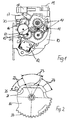
- a known belt retractor has a U-shaped Housing on, in the side housing plates, of which in Figure 1, a housing plate 10 can be seen, a Belt shaft 11 is stored. As can be seen from FIG. 1, the belt shaft 11 carries a firmly connected with her Worm gear 13. On the side housing plate 10 is a vehicle-sensitive sensor 12 is arranged, whose Function with self-locking belt retractors from the state The technique is well known.
- the shaft gear 13 a from two other gears existing reduction gear 15 is connected, which is a rotatably mounted on the housing plate 10 Ratchet 16 acted upon.
- the ratchet wheel 16 via a part of its outer periphery with an outer toothing 20th Mistake.
- the ratchet 16 is an electric switch 17th assigned, from which one shown in Figure 2 Stick pin 25 protrudes and on one of the ratchet 16th trained switching contour 21 is guided, wherein the Electric switch 17 with a switch housing 18 for the pyrotechnically operated switching device for adjustment the clamping length of the force limiting device forming, not shown in detail torsion bar is coupled.
- the belt retractor also has a Connection 19 for a coming from the vehicle Energy supply on.
- Switching contour 21 formed with three areas, namely a first region 22, a second region 23 and a third area 24, wherein the areas 22, 23, 24 at the Pivoting the ratchet wheel 16 of the adjacent thereto stationary switching pin 25 are run over.
- the assignment the switching wheel 16 is affected in such a way that in the first area 22 a position of the switching pin 25th is effected, in which the electric switch 17 a Deactivation of the pyrotechnic switching device so in case of a sensed accident the pyrotechnic switching device is not triggered.
- This first region 22 corresponds to a position of Belt shaft 11 with fully or almost fully wound Webbing, so when stored seat belt or only slightly pulled webbing, and in this Belt pulley position is a trigger of Switching device not required or not desired.
Landscapes
- Engineering & Computer Science (AREA)
- Mechanical Engineering (AREA)
- Automotive Seat Belt Assembly (AREA)
- Devices For Conveying Motion By Means Of Endless Flexible Members (AREA)
- Emergency Lowering Means (AREA)
Claims (2)
- Enrouleur de ceinture de sécurité comportant un arbre à courroie (11) fixé dans un logement faisant office de support d'une courroie enroulable et déroulable sur ce dernier, l'enrouleur de ceinture présentant un dispositif de limitation de force fonctionnant sur plusieurs étages, avec une barre de torsion et un dispositif de commutation provoquant le couplage de la barre de torsion avec l'arbre à courroie (11) à différentes longueurs de serrage et la mesure de la courroie déroulée de l'arbre à courroie (11) servant de référence pour la commutation du dispositif de limitation de force, caractérisé en ce qu'il est prévu une barre de torsion à deux étages avec un dispositif de commutation fonctionnant de manière pyrotechnique et en ce qu'une roue de commande (16) raccordée à l'arbre à courroie (11) est disposée par le biais d'un réducteur (15), la roue de commande (16) présentant, sur une partie de sa circonférence, une denture (20) pour l'engagement du réducteur (15), et, sur une autre partie de sa circonférence, un contour de commutation (21) en appui contre une tige de commutation (25) d'un interrupteur électrique (17) raccordé au dispositif de commutation pour la tige de torsion, et le contour de commutation (21) étant conformé selon un tracé provoquant l'activation ou la désactivation du dispositif de commutation pour la tige de torsion.
- Enrouleur de ceinture de sécurité selon la revendication 1 caractérisé en ce que le contour de commutation (21), partant de la position de la roue de commande (16) où la courroie est totalement enroulée, présente un premier tronçon (22) permettant l'appui de la tige de commutation (25) entraínant dans cette position une désactivation du déclenchement du dispositif de commutation pyrotechnique, et un second tronçon (23) qui prolonge le premier tronçon (22) et qui est parcouru par la tige de commutation (25) lors de la rotation de l'arbre à courroie (11), le dispositif de commutation pyrotechnique pouvant être déclenché dans la position de la tige de commutation (25) où celle-ci est en appui sur le second tronçon (23) du contour de commutation (21), et en ce que le second tronçon (23) est poursuivi par un troisième tronçon (24) du contour de commutation (21) permettant un appui de la tige de commutation (25), et en ce que la tige de commutation (25) désactive, dans sa position en appui contre le troisième tronçon (24) du contour de commutation (21), le déclenchement du dispositif de commutation pyrotechnique.
Applications Claiming Priority (3)
| Application Number | Priority Date | Filing Date | Title |
|---|---|---|---|
| DE20109114U | 2001-05-31 | ||
| DE20109114U DE20109114U1 (de) | 2001-05-31 | 2001-05-31 | Sicherheitsgurtaufroller mit einer in Abhängigkeit vom Gurtbandauszug schaltbaren Kraftbegrenzungseinrichtung |
| PCT/EP2002/005765 WO2002096724A1 (fr) | 2001-05-31 | 2002-05-25 | Enrouleur de ceinture de securite muni d'un systeme de limitation de force actionnable en fonction de la section de sangle sortie |
Publications (2)
| Publication Number | Publication Date |
|---|---|
| EP1414681A1 EP1414681A1 (fr) | 2004-05-06 |
| EP1414681B1 true EP1414681B1 (fr) | 2005-07-27 |
Family
ID=7957571
Family Applications (1)
| Application Number | Title | Priority Date | Filing Date |
|---|---|---|---|
| EP02743104A Expired - Lifetime EP1414681B1 (fr) | 2001-05-31 | 2002-05-25 | Enrouleur de ceinture de securite muni d'un systeme de limitation de force actionnable en fonction de la section de sangle sortie |
Country Status (6)
| Country | Link |
|---|---|
| US (2) | US20040188995A1 (fr) |
| EP (1) | EP1414681B1 (fr) |
| JP (1) | JP4135174B2 (fr) |
| AT (1) | ATE300450T1 (fr) |
| DE (2) | DE20109114U1 (fr) |
| WO (1) | WO2002096724A1 (fr) |
Families Citing this family (13)
| Publication number | Priority date | Publication date | Assignee | Title |
|---|---|---|---|---|
| WO2007007480A1 (fr) | 2005-07-14 | 2007-01-18 | Autoliv Development Ab | Dispositif de ceinture de sécurité |
| ES2346472T3 (es) * | 2005-12-19 | 2010-10-15 | Autoliv Development Ab | Arrollador de cinturon de seguridad con un dispositivo de limitacion de fuerza controlado por la extraccion del cinturon. |
| DE102007026128A1 (de) * | 2006-11-02 | 2008-05-08 | Trw Automotive Gmbh | Gurtaufroller |
| US7946519B2 (en) * | 2008-11-12 | 2011-05-24 | Tk Holdings Inc. | Pretensioned retractor |
| JP5420264B2 (ja) * | 2009-02-12 | 2014-02-19 | テイ・エス テック株式会社 | 車両用シート |
| US20100213302A1 (en) * | 2009-02-26 | 2010-08-26 | Tk Holdings Inc. | Retractor assembly |
| DE102009011091B4 (de) * | 2009-03-03 | 2017-02-23 | Autoliv Development Ab | Gurtaufroller mit einer Einrichtung zur Sensierung der Gurtbandauszugslänge |
| DE102011015862B4 (de) * | 2011-04-01 | 2020-07-23 | Autoliv Development Ab | Sicherheitsgurtaufroller mit einem Trägheitssensor mit einem verschwenkbaren Sensorgehäuse |
| DE102012209355B4 (de) * | 2012-06-04 | 2014-10-09 | Autoliv Development Ab | Gurtaufroller mit einer Kraftbegrenzungseinrichtung |
| US9150193B2 (en) | 2012-06-14 | 2015-10-06 | Autoliv Asp, Inc. | Mode detection switch assembly for self-locking dual-mode seat belt retractor |
| CN109153369B (zh) * | 2016-04-06 | 2021-05-07 | Trw汽车股份有限公司 | 用于释放用于车辆安全带的安全带卷收器的力限制器的执行机构以及具有这种执行机构的安全带卷收器 |
| DE102016007375A1 (de) * | 2016-06-16 | 2017-12-21 | GM Global Technology Operations LLC (n. d. Ges. d. Staates Delaware) | Gurtautomat |
| DE102019218307A1 (de) * | 2019-11-26 | 2021-05-27 | Autoliv Development Ab | Gurtaufroller |
Family Cites Families (13)
| Publication number | Priority date | Publication date | Assignee | Title |
|---|---|---|---|---|
| DE2727470A1 (de) | 1977-06-18 | 1979-01-04 | Volkswagenwerk Ag | Sicherheitsgurteinrichtung fuer fahrzeuge, insbesondere kraftfahrzeuge |
| JPS56124532A (en) * | 1980-03-07 | 1981-09-30 | Takata Kk | Seat belt retractor with memory |
| JP2579426Y2 (ja) * | 1992-01-31 | 1998-08-27 | 富士機工株式会社 | 安全ベルト用リトラクタ |
| BR9709962A (pt) * | 1996-06-26 | 1999-08-10 | Autoliv Dev | Dispositivo enrolador de cinta com dispositivo de limitação de força ajustável |
| JP3674800B2 (ja) * | 1996-10-17 | 2005-07-20 | エヌエスケー・オートリブ株式会社 | シートベルト用リトラクター |
| US6702056B2 (en) * | 1997-08-06 | 2004-03-09 | Takata Corporation | Seatbelt retractor |
| DE29820086U1 (de) * | 1998-11-10 | 1999-04-01 | TRW Occupant Restraint Systems GmbH & Co. KG, 73553 Alfdorf | Gurtaufroller für einen Fahrzeug-Sicherheitsgurt |
| DE29821801U1 (de) * | 1998-12-07 | 1999-04-08 | TRW Occupant Restraint Systems GmbH & Co. KG, 73553 Alfdorf | Gurtaufroller für einen Fahrzeug-Sicherheitsgurt |
| DE19907962B4 (de) * | 1999-02-24 | 2010-11-18 | Takata-Petri Ag | Sicherheitsgurtvorrichtung mit Gurtstraffer |
| GB2354742B (en) * | 1999-08-06 | 2003-08-13 | Takata Corp | A seat belt retractor |
| JP2001163181A (ja) * | 1999-12-06 | 2001-06-19 | Tokai Rika Co Ltd | ウエビング巻取装置 |
| EP1298017B1 (fr) * | 2001-09-27 | 2004-11-03 | Key Safety Systems, Inc. | Enrouleur de ceinture de sécurité avec mécanisme de blocage automatique |
| JP2003154922A (ja) * | 2001-11-19 | 2003-05-27 | Tokai Rika Co Ltd | プリテンショナ装置及びシートベルト装置 |
-
2001
- 2001-05-31 DE DE20109114U patent/DE20109114U1/de not_active Expired - Lifetime
-
2002
- 2002-05-25 EP EP02743104A patent/EP1414681B1/fr not_active Expired - Lifetime
- 2002-05-25 US US10/478,933 patent/US20040188995A1/en not_active Abandoned
- 2002-05-25 WO PCT/EP2002/005765 patent/WO2002096724A1/fr not_active Ceased
- 2002-05-25 AT AT02743104T patent/ATE300450T1/de not_active IP Right Cessation
- 2002-05-25 DE DE50203776T patent/DE50203776D1/de not_active Expired - Lifetime
- 2002-05-25 JP JP2002593211A patent/JP4135174B2/ja not_active Expired - Fee Related
-
2006
- 2006-09-01 US US11/583,293 patent/US7690688B2/en not_active Expired - Fee Related
Also Published As
| Publication number | Publication date |
|---|---|
| ATE300450T1 (de) | 2005-08-15 |
| DE50203776D1 (de) | 2005-09-01 |
| EP1414681A1 (fr) | 2004-05-06 |
| US20040188995A1 (en) | 2004-09-30 |
| DE20109114U1 (de) | 2001-09-27 |
| JP2004521016A (ja) | 2004-07-15 |
| US7690688B2 (en) | 2010-04-06 |
| JP4135174B2 (ja) | 2008-08-20 |
| US20070145175A1 (en) | 2007-06-28 |
| WO2002096724A1 (fr) | 2002-12-05 |
Similar Documents
| Publication | Publication Date | Title |
|---|---|---|
| DE19927427C2 (de) | Gurtaufroller mit schaltbarem Kraftbegrenzer | |
| DE19780583C1 (de) | Gurtaufroller mit regelbarer Kraftbegrenzungseinrichtung | |
| EP0895906B1 (fr) | Enrouleur pour une ceinture de sécurité d'un siège de passager | |
| DE3342478C2 (de) | Gurtaufroller | |
| DE60313198T2 (de) | Gurtaufroller | |
| DE19935248C1 (de) | Sicherheitsgurtsystem | |
| EP1414681B1 (fr) | Enrouleur de ceinture de securite muni d'un systeme de limitation de force actionnable en fonction de la section de sangle sortie | |
| DE2542530A1 (de) | Vorrichtung fuer die zugentlastung an einem sicherheitsgurt | |
| WO1997033778A1 (fr) | Systeme combine pour enrouler et tendre une ceinture, muni d'un limiteur de force | |
| WO2014048560A1 (fr) | Enrouleur pour ceinture de sécurité | |
| DE2419937C2 (de) | Aufwickelvorrichtung mit Gurtkraftbegrenzung | |
| DE10025031B4 (de) | Sicherheitsgurtsystem mit elektrischem Antrieb seiner Komponenten | |
| EP1008498B1 (fr) | Rétracteur pour une ceinture de sécurité de véhicule et procédé d'actionnement d'un rétracteur | |
| EP1963146B1 (fr) | Enrouleur de ceinture de securite comportant un limitateur de force commande en fonction de l'extraction de la ceinture | |
| EP1551676B1 (fr) | Enrouleur de ceinture de securite a pretensionneur | |
| DE2456670C2 (de) | Spanneinrichtung für einen Sicherheitsgurt | |
| DE20015402U1 (de) | Gurtaufroller für einen Fahrzeugsicherheitsgurt | |
| DE19541430C2 (de) | Elektrisch gesteuerter Sicherheitsgurtaufroller | |
| DE60116896T2 (de) | Sicherheitsgurtaufrolleinrichtung mit lastbegrenzer | |
| DE60107105T2 (de) | Sicherheitsgurtanordnung | |
| DE10066141B4 (de) | Gurtaufroller mit einer als Blechbiegebremse ausgebildeten Kraftbegrenzungseinrichtung | |
| DE20113834U1 (de) | Gurtaufroller für einen Fahrzeugsicherheitsgurt | |
| DE10162374C1 (de) | Sicherheitsgurtaufroller mit elektromotorischer Vorstraffung und Komfortfedersystem | |
| DE1755464B1 (de) | Energieobs?ibir fuer Sicherheitsgurte oder Sitze von Fahrzeugen | |
| DE2108718A1 (de) | Sicherheitsgurt |
Legal Events
| Date | Code | Title | Description |
|---|---|---|---|
| PUAI | Public reference made under article 153(3) epc to a published international application that has entered the european phase |
Free format text: ORIGINAL CODE: 0009012 |
|
| 17P | Request for examination filed |
Effective date: 20040225 |
|
| AK | Designated contracting states |
Kind code of ref document: A1 Designated state(s): AT BE CH CY DE DK ES FI FR GB GR IE IT LI LU MC NL PT SE TR |
|
| AX | Request for extension of the european patent |
Extension state: AL LT LV MK RO SI |
|
| GRAP | Despatch of communication of intention to grant a patent |
Free format text: ORIGINAL CODE: EPIDOSNIGR1 |
|
| GRAS | Grant fee paid |
Free format text: ORIGINAL CODE: EPIDOSNIGR3 |
|
| GRAA | (expected) grant |
Free format text: ORIGINAL CODE: 0009210 |
|
| AK | Designated contracting states |
Kind code of ref document: B1 Designated state(s): AT BE CH CY DE DK ES FI FR GB GR IE IT LI LU MC NL PT SE TR |
|
| PG25 | Lapsed in a contracting state [announced via postgrant information from national office to epo] |
Ref country code: IT Free format text: LAPSE BECAUSE OF FAILURE TO SUBMIT A TRANSLATION OF THE DESCRIPTION OR TO PAY THE FEE WITHIN THE PRESCRIBED TIME-LIMIT;WARNING: LAPSES OF ITALIAN PATENTS WITH EFFECTIVE DATE BEFORE 2007 MAY HAVE OCCURRED AT ANY TIME BEFORE 2007. THE CORRECT EFFECTIVE DATE MAY BE DIFFERENT FROM THE ONE RECORDED. Effective date: 20050727 Ref country code: FI Free format text: LAPSE BECAUSE OF FAILURE TO SUBMIT A TRANSLATION OF THE DESCRIPTION OR TO PAY THE FEE WITHIN THE PRESCRIBED TIME-LIMIT Effective date: 20050727 Ref country code: NL Free format text: LAPSE BECAUSE OF FAILURE TO SUBMIT A TRANSLATION OF THE DESCRIPTION OR TO PAY THE FEE WITHIN THE PRESCRIBED TIME-LIMIT Effective date: 20050727 Ref country code: IE Free format text: LAPSE BECAUSE OF FAILURE TO SUBMIT A TRANSLATION OF THE DESCRIPTION OR TO PAY THE FEE WITHIN THE PRESCRIBED TIME-LIMIT Effective date: 20050727 Ref country code: TR Free format text: LAPSE BECAUSE OF FAILURE TO SUBMIT A TRANSLATION OF THE DESCRIPTION OR TO PAY THE FEE WITHIN THE PRESCRIBED TIME-LIMIT Effective date: 20050727 Ref country code: GB Free format text: LAPSE BECAUSE OF FAILURE TO SUBMIT A TRANSLATION OF THE DESCRIPTION OR TO PAY THE FEE WITHIN THE PRESCRIBED TIME-LIMIT Effective date: 20050727 |
|
| REG | Reference to a national code |
Ref country code: GB Ref legal event code: FG4D Free format text: NOT ENGLISH |
|
| REG | Reference to a national code |
Ref country code: CH Ref legal event code: EP |
|
| REG | Reference to a national code |
Ref country code: IE Ref legal event code: FG4D Free format text: LANGUAGE OF EP DOCUMENT: GERMAN |
|
| REF | Corresponds to: |
Ref document number: 50203776 Country of ref document: DE Date of ref document: 20050901 Kind code of ref document: P |
|
| PG25 | Lapsed in a contracting state [announced via postgrant information from national office to epo] |
Ref country code: SE Free format text: LAPSE BECAUSE OF FAILURE TO SUBMIT A TRANSLATION OF THE DESCRIPTION OR TO PAY THE FEE WITHIN THE PRESCRIBED TIME-LIMIT Effective date: 20051027 Ref country code: GR Free format text: LAPSE BECAUSE OF FAILURE TO SUBMIT A TRANSLATION OF THE DESCRIPTION OR TO PAY THE FEE WITHIN THE PRESCRIBED TIME-LIMIT Effective date: 20051027 Ref country code: DK Free format text: LAPSE BECAUSE OF FAILURE TO SUBMIT A TRANSLATION OF THE DESCRIPTION OR TO PAY THE FEE WITHIN THE PRESCRIBED TIME-LIMIT Effective date: 20051027 |
|
| PG25 | Lapsed in a contracting state [announced via postgrant information from national office to epo] |
Ref country code: PT Free format text: LAPSE BECAUSE OF FAILURE TO SUBMIT A TRANSLATION OF THE DESCRIPTION OR TO PAY THE FEE WITHIN THE PRESCRIBED TIME-LIMIT Effective date: 20051227 |
|
| NLV1 | Nl: lapsed or annulled due to failure to fulfill the requirements of art. 29p and 29m of the patents act | ||
| GBV | Gb: ep patent (uk) treated as always having been void in accordance with gb section 77(7)/1977 [no translation filed] |
Effective date: 20050727 |
|
| REG | Reference to a national code |
Ref country code: IE Ref legal event code: FD4D |
|
| ET | Fr: translation filed | ||
| PG25 | Lapsed in a contracting state [announced via postgrant information from national office to epo] |
Ref country code: AT Free format text: LAPSE BECAUSE OF NON-PAYMENT OF DUE FEES Effective date: 20060525 |
|
| PG25 | Lapsed in a contracting state [announced via postgrant information from national office to epo] |
Ref country code: LI Free format text: LAPSE BECAUSE OF NON-PAYMENT OF DUE FEES Effective date: 20060531 Ref country code: CH Free format text: LAPSE BECAUSE OF NON-PAYMENT OF DUE FEES Effective date: 20060531 Ref country code: BE Free format text: LAPSE BECAUSE OF NON-PAYMENT OF DUE FEES Effective date: 20060531 Ref country code: MC Free format text: LAPSE BECAUSE OF NON-PAYMENT OF DUE FEES Effective date: 20060531 |
|
| PLBE | No opposition filed within time limit |
Free format text: ORIGINAL CODE: 0009261 |
|
| STAA | Information on the status of an ep patent application or granted ep patent |
Free format text: STATUS: NO OPPOSITION FILED WITHIN TIME LIMIT |
|
| 26N | No opposition filed |
Effective date: 20060428 |
|
| REG | Reference to a national code |
Ref country code: CH Ref legal event code: PL |
|
| BERE | Be: lapsed |
Owner name: AUTOLIV DEVELOPMENT A.B. Effective date: 20060531 |
|
| PG25 | Lapsed in a contracting state [announced via postgrant information from national office to epo] |
Ref country code: LU Free format text: LAPSE BECAUSE OF NON-PAYMENT OF DUE FEES Effective date: 20060525 |
|
| PG25 | Lapsed in a contracting state [announced via postgrant information from national office to epo] |
Ref country code: CY Free format text: LAPSE BECAUSE OF FAILURE TO SUBMIT A TRANSLATION OF THE DESCRIPTION OR TO PAY THE FEE WITHIN THE PRESCRIBED TIME-LIMIT Effective date: 20050727 |
|
| PG25 | Lapsed in a contracting state [announced via postgrant information from national office to epo] |
Ref country code: ES Free format text: LAPSE BECAUSE OF NON-PAYMENT OF DUE FEES Effective date: 20060531 |
|
| REG | Reference to a national code |
Ref country code: FR Ref legal event code: PLFP Year of fee payment: 15 |
|
| REG | Reference to a national code |
Ref country code: FR Ref legal event code: PLFP Year of fee payment: 16 |
|
| REG | Reference to a national code |
Ref country code: FR Ref legal event code: PLFP Year of fee payment: 17 |
|
| PGFP | Annual fee paid to national office [announced via postgrant information from national office to epo] |
Ref country code: FR Payment date: 20200527 Year of fee payment: 19 |
|
| PGFP | Annual fee paid to national office [announced via postgrant information from national office to epo] |
Ref country code: DE Payment date: 20210525 Year of fee payment: 20 |
|
| REG | Reference to a national code |
Ref country code: DE Ref legal event code: R071 Ref document number: 50203776 Country of ref document: DE |
|
| PG25 | Lapsed in a contracting state [announced via postgrant information from national office to epo] |
Ref country code: FR Free format text: LAPSE BECAUSE OF NON-PAYMENT OF DUE FEES Effective date: 20210531 |