EP1414708B1 - Recipient muni de son couvercle - Google Patents
Recipient muni de son couvercle Download PDFInfo
- Publication number
- EP1414708B1 EP1414708B1 EP02779256A EP02779256A EP1414708B1 EP 1414708 B1 EP1414708 B1 EP 1414708B1 EP 02779256 A EP02779256 A EP 02779256A EP 02779256 A EP02779256 A EP 02779256A EP 1414708 B1 EP1414708 B1 EP 1414708B1
- Authority
- EP
- European Patent Office
- Prior art keywords
- flap
- container
- flange
- tab
- tool
- Prior art date
- Legal status (The legal status is an assumption and is not a legal conclusion. Google has not performed a legal analysis and makes no representation as to the accuracy of the status listed.)
- Expired - Lifetime
Links
Images




Classifications
-
- B—PERFORMING OPERATIONS; TRANSPORTING
- B65—CONVEYING; PACKING; STORING; HANDLING THIN OR FILAMENTARY MATERIAL
- B65D—CONTAINERS FOR STORAGE OR TRANSPORT OF ARTICLES OR MATERIALS, e.g. BAGS, BARRELS, BOTTLES, BOXES, CANS, CARTONS, CRATES, DRUMS, JARS, TANKS, HOPPERS, FORWARDING CONTAINERS; ACCESSORIES, CLOSURES, OR FITTINGS THEREFOR; PACKAGING ELEMENTS; PACKAGES
- B65D43/00—Lids or covers for rigid or semi-rigid containers
- B65D43/02—Removable lids or covers
- B65D43/0202—Removable lids or covers without integral tamper element
- B65D43/0204—Removable lids or covers without integral tamper element secured by snapping over beads or projections
- B65D43/0212—Removable lids or covers without integral tamper element secured by snapping over beads or projections only on the outside, or a part turned to the outside, of the mouth
-
- B—PERFORMING OPERATIONS; TRANSPORTING
- B65—CONVEYING; PACKING; STORING; HANDLING THIN OR FILAMENTARY MATERIAL
- B65D—CONTAINERS FOR STORAGE OR TRANSPORT OF ARTICLES OR MATERIALS, e.g. BAGS, BARRELS, BOTTLES, BOXES, CANS, CARTONS, CRATES, DRUMS, JARS, TANKS, HOPPERS, FORWARDING CONTAINERS; ACCESSORIES, CLOSURES, OR FITTINGS THEREFOR; PACKAGING ELEMENTS; PACKAGES
- B65D2401/00—Tamper-indicating means
- B65D2401/10—Tearable part of the container
-
- B—PERFORMING OPERATIONS; TRANSPORTING
- B65—CONVEYING; PACKING; STORING; HANDLING THIN OR FILAMENTARY MATERIAL
- B65D—CONTAINERS FOR STORAGE OR TRANSPORT OF ARTICLES OR MATERIALS, e.g. BAGS, BARRELS, BOTTLES, BOXES, CANS, CARTONS, CRATES, DRUMS, JARS, TANKS, HOPPERS, FORWARDING CONTAINERS; ACCESSORIES, CLOSURES, OR FITTINGS THEREFOR; PACKAGING ELEMENTS; PACKAGES
- B65D2543/00—Lids or covers essentially for box-like containers
- B65D2543/00009—Details of lids or covers for rigid or semi-rigid containers
- B65D2543/00018—Overall construction of the lid
- B65D2543/00064—Shape of the outer periphery
- B65D2543/00074—Shape of the outer periphery curved
- B65D2543/00092—Shape of the outer periphery curved circular
-
- B—PERFORMING OPERATIONS; TRANSPORTING
- B65—CONVEYING; PACKING; STORING; HANDLING THIN OR FILAMENTARY MATERIAL
- B65D—CONTAINERS FOR STORAGE OR TRANSPORT OF ARTICLES OR MATERIALS, e.g. BAGS, BARRELS, BOTTLES, BOXES, CANS, CARTONS, CRATES, DRUMS, JARS, TANKS, HOPPERS, FORWARDING CONTAINERS; ACCESSORIES, CLOSURES, OR FITTINGS THEREFOR; PACKAGING ELEMENTS; PACKAGES
- B65D2543/00—Lids or covers essentially for box-like containers
- B65D2543/00009—Details of lids or covers for rigid or semi-rigid containers
- B65D2543/00018—Overall construction of the lid
- B65D2543/00259—Materials used
- B65D2543/00296—Plastic
-
- B—PERFORMING OPERATIONS; TRANSPORTING
- B65—CONVEYING; PACKING; STORING; HANDLING THIN OR FILAMENTARY MATERIAL
- B65D—CONTAINERS FOR STORAGE OR TRANSPORT OF ARTICLES OR MATERIALS, e.g. BAGS, BARRELS, BOTTLES, BOXES, CANS, CARTONS, CRATES, DRUMS, JARS, TANKS, HOPPERS, FORWARDING CONTAINERS; ACCESSORIES, CLOSURES, OR FITTINGS THEREFOR; PACKAGING ELEMENTS; PACKAGES
- B65D2543/00—Lids or covers essentially for box-like containers
- B65D2543/00009—Details of lids or covers for rigid or semi-rigid containers
- B65D2543/00342—Central part of the lid
- B65D2543/00398—Reinforcing ribs in the central part of the closure
- B65D2543/00416—Reinforcing ribs in the central part of the closure circular
-
- B—PERFORMING OPERATIONS; TRANSPORTING
- B65—CONVEYING; PACKING; STORING; HANDLING THIN OR FILAMENTARY MATERIAL
- B65D—CONTAINERS FOR STORAGE OR TRANSPORT OF ARTICLES OR MATERIALS, e.g. BAGS, BARRELS, BOTTLES, BOXES, CANS, CARTONS, CRATES, DRUMS, JARS, TANKS, HOPPERS, FORWARDING CONTAINERS; ACCESSORIES, CLOSURES, OR FITTINGS THEREFOR; PACKAGING ELEMENTS; PACKAGES
- B65D2543/00—Lids or covers essentially for box-like containers
- B65D2543/00009—Details of lids or covers for rigid or semi-rigid containers
- B65D2543/00444—Contact between the container and the lid
- B65D2543/00481—Contact between the container and the lid on the inside or the outside of the container
- B65D2543/0049—Contact between the container and the lid on the inside or the outside of the container on the inside, or a part turned to the inside of the mouth of the container
- B65D2543/005—Contact between the container and the lid on the inside or the outside of the container on the inside, or a part turned to the inside of the mouth of the container both cup and skirt
-
- B—PERFORMING OPERATIONS; TRANSPORTING
- B65—CONVEYING; PACKING; STORING; HANDLING THIN OR FILAMENTARY MATERIAL
- B65D—CONTAINERS FOR STORAGE OR TRANSPORT OF ARTICLES OR MATERIALS, e.g. BAGS, BARRELS, BOTTLES, BOXES, CANS, CARTONS, CRATES, DRUMS, JARS, TANKS, HOPPERS, FORWARDING CONTAINERS; ACCESSORIES, CLOSURES, OR FITTINGS THEREFOR; PACKAGING ELEMENTS; PACKAGES
- B65D2543/00—Lids or covers essentially for box-like containers
- B65D2543/00009—Details of lids or covers for rigid or semi-rigid containers
- B65D2543/00444—Contact between the container and the lid
- B65D2543/00481—Contact between the container and the lid on the inside or the outside of the container
- B65D2543/00537—Contact between the container and the lid on the inside or the outside of the container on the outside, or a part turned to the outside of the mouth of the container
-
- B—PERFORMING OPERATIONS; TRANSPORTING
- B65—CONVEYING; PACKING; STORING; HANDLING THIN OR FILAMENTARY MATERIAL
- B65D—CONTAINERS FOR STORAGE OR TRANSPORT OF ARTICLES OR MATERIALS, e.g. BAGS, BARRELS, BOTTLES, BOXES, CANS, CARTONS, CRATES, DRUMS, JARS, TANKS, HOPPERS, FORWARDING CONTAINERS; ACCESSORIES, CLOSURES, OR FITTINGS THEREFOR; PACKAGING ELEMENTS; PACKAGES
- B65D2543/00—Lids or covers essentially for box-like containers
- B65D2543/00009—Details of lids or covers for rigid or semi-rigid containers
- B65D2543/00444—Contact between the container and the lid
- B65D2543/00481—Contact between the container and the lid on the inside or the outside of the container
- B65D2543/00555—Contact between the container and the lid on the inside or the outside of the container on both the inside and the outside
-
- B—PERFORMING OPERATIONS; TRANSPORTING
- B65—CONVEYING; PACKING; STORING; HANDLING THIN OR FILAMENTARY MATERIAL
- B65D—CONTAINERS FOR STORAGE OR TRANSPORT OF ARTICLES OR MATERIALS, e.g. BAGS, BARRELS, BOTTLES, BOXES, CANS, CARTONS, CRATES, DRUMS, JARS, TANKS, HOPPERS, FORWARDING CONTAINERS; ACCESSORIES, CLOSURES, OR FITTINGS THEREFOR; PACKAGING ELEMENTS; PACKAGES
- B65D2543/00—Lids or covers essentially for box-like containers
- B65D2543/00009—Details of lids or covers for rigid or semi-rigid containers
- B65D2543/00444—Contact between the container and the lid
- B65D2543/00592—Snapping means
- B65D2543/00601—Snapping means on the container
- B65D2543/00611—Profiles
- B65D2543/0062—Groove or hollow bead
-
- B—PERFORMING OPERATIONS; TRANSPORTING
- B65—CONVEYING; PACKING; STORING; HANDLING THIN OR FILAMENTARY MATERIAL
- B65D—CONTAINERS FOR STORAGE OR TRANSPORT OF ARTICLES OR MATERIALS, e.g. BAGS, BARRELS, BOTTLES, BOXES, CANS, CARTONS, CRATES, DRUMS, JARS, TANKS, HOPPERS, FORWARDING CONTAINERS; ACCESSORIES, CLOSURES, OR FITTINGS THEREFOR; PACKAGING ELEMENTS; PACKAGES
- B65D2543/00—Lids or covers essentially for box-like containers
- B65D2543/00009—Details of lids or covers for rigid or semi-rigid containers
- B65D2543/00444—Contact between the container and the lid
- B65D2543/00592—Snapping means
- B65D2543/00601—Snapping means on the container
- B65D2543/00675—Periphery concerned
- B65D2543/00685—Totality
-
- B—PERFORMING OPERATIONS; TRANSPORTING
- B65—CONVEYING; PACKING; STORING; HANDLING THIN OR FILAMENTARY MATERIAL
- B65D—CONTAINERS FOR STORAGE OR TRANSPORT OF ARTICLES OR MATERIALS, e.g. BAGS, BARRELS, BOTTLES, BOXES, CANS, CARTONS, CRATES, DRUMS, JARS, TANKS, HOPPERS, FORWARDING CONTAINERS; ACCESSORIES, CLOSURES, OR FITTINGS THEREFOR; PACKAGING ELEMENTS; PACKAGES
- B65D2543/00—Lids or covers essentially for box-like containers
- B65D2543/00009—Details of lids or covers for rigid or semi-rigid containers
- B65D2543/00444—Contact between the container and the lid
- B65D2543/00592—Snapping means
- B65D2543/00712—Snapping means on the lid
- B65D2543/00722—Profiles
- B65D2543/0074—Massive bead
-
- B—PERFORMING OPERATIONS; TRANSPORTING
- B65—CONVEYING; PACKING; STORING; HANDLING THIN OR FILAMENTARY MATERIAL
- B65D—CONTAINERS FOR STORAGE OR TRANSPORT OF ARTICLES OR MATERIALS, e.g. BAGS, BARRELS, BOTTLES, BOXES, CANS, CARTONS, CRATES, DRUMS, JARS, TANKS, HOPPERS, FORWARDING CONTAINERS; ACCESSORIES, CLOSURES, OR FITTINGS THEREFOR; PACKAGING ELEMENTS; PACKAGES
- B65D2543/00—Lids or covers essentially for box-like containers
- B65D2543/00009—Details of lids or covers for rigid or semi-rigid containers
- B65D2543/00444—Contact between the container and the lid
- B65D2543/00592—Snapping means
- B65D2543/00712—Snapping means on the lid
- B65D2543/00787—Periphery concerned
- B65D2543/00796—Totality
-
- B—PERFORMING OPERATIONS; TRANSPORTING
- B65—CONVEYING; PACKING; STORING; HANDLING THIN OR FILAMENTARY MATERIAL
- B65D—CONTAINERS FOR STORAGE OR TRANSPORT OF ARTICLES OR MATERIALS, e.g. BAGS, BARRELS, BOTTLES, BOXES, CANS, CARTONS, CRATES, DRUMS, JARS, TANKS, HOPPERS, FORWARDING CONTAINERS; ACCESSORIES, CLOSURES, OR FITTINGS THEREFOR; PACKAGING ELEMENTS; PACKAGES
- B65D2543/00—Lids or covers essentially for box-like containers
- B65D2543/00009—Details of lids or covers for rigid or semi-rigid containers
- B65D2543/00824—Means for facilitating removing of the closure
- B65D2543/00944—Located only on the container, e.g. recesses
-
- B—PERFORMING OPERATIONS; TRANSPORTING
- B65—CONVEYING; PACKING; STORING; HANDLING THIN OR FILAMENTARY MATERIAL
- B65D—CONTAINERS FOR STORAGE OR TRANSPORT OF ARTICLES OR MATERIALS, e.g. BAGS, BARRELS, BOTTLES, BOXES, CANS, CARTONS, CRATES, DRUMS, JARS, TANKS, HOPPERS, FORWARDING CONTAINERS; ACCESSORIES, CLOSURES, OR FITTINGS THEREFOR; PACKAGING ELEMENTS; PACKAGES
- B65D2543/00—Lids or covers essentially for box-like containers
- B65D2543/00009—Details of lids or covers for rigid or semi-rigid containers
- B65D2543/00953—Sealing means
- B65D2543/0099—Integral supplemental sealing lips
Definitions
- the invention relates to a container with an upwardly facing opening, at the edge of a circumferential flange is provided, which is preferably formed for receiving a lid for closing the container, by latching, wherein the flange in at least one area of a tool to form two Flanged ends is interrupted, which has a hinged to the container at a first hinge tab which is arranged such that an attached lid by a pivoting of the tab outwardly in the region of the tool is partially raised to facilitate opening of the lid.
- Such a container is from the EP 0 565 967 B2 known.
- the known container is made of a resilient plastic material and has a circumferential flange which is interrupted in a region of a tool to form two Flanschenden.
- the tool is designed as a tab, which is connected at an upper end via a film hinge with the wall of the container.
- An initial pivoting of the flap to pry the lid is made recognizable by Abrißstege, which are arranged between the side edges of the tab and the opposite flange ends.
- Such containers are in use for decades and are u. a. used to hold inks, such as emulsion paints, but also to hold any other materials.
- the tool and the display device such that a first-time opening is reliably recognizable before the lid edge is already partially raised by means of the tool, without this being visually recognizable with the display device. Also, the prying open of the lid should be possible in the simplest possible and energy-saving manner.
- the invention is therefore based on the object to provide an improved container in which the disadvantages of the prior art are avoided as possible.
- the lid should be able to be opened in the simplest and most energy-saving manner by means of the tool provided in the region of the bottle on the container wall.
- This should also be a first-time operation of the tab in the simplest possible way is made recognizable and Abrissstege between the two side edges of the tab and the opposite end of the flange dispensable..sind.
- a container according to claim 1 characterized in that the tab is associated with a second element in the form of a safety lever or a support bar or the tab of a second tab segment, wherein this further element in each case cooperates with the container wall such that this at the Container wall is fixed, secured or arranged.
- the tab acts independently of the flange with the container wall, whereby a first-time operation of the tab in the simplest possible way is made independent of between the side edges of the tabs and the opposing flange disposed tear-off webs made recognizable.
- the pivot point of the tab (first hinge) can be moved closer to the upper edge of the container, which leads to a significantly extended lever arm, whereby a lever-up of the lid edge is simplified.
- the safety lever In order to enable a pivoting of the tab to the outside, the safety lever must first be pivoted in the direction of the container wall, wherein preferably at least one indicator element, via which the tab is connected to the safety lever, is destroyed. Only when the lower edge of the tab is released by the pivoting of the safety lever, the tab can be engaged behind and pivoted upwards to lift the lid edge.
- At the first pivoting of the tab outwardly or above at least one indicator element is damaged approximately in the form of at least one Abrißsteges between tab and safety lever, so that the first-time opening of the tab is displayed.
- the safety lever is substantially U-shaped and separated from the tab via a substantially U-shaped recess.
- the safety lever may have at least one locking element which cooperates with a counter element to fix the safety lever in a pivoted to the wall of the container position.
- locking projections may be provided approximately at the ends of the locking lever facing the flange ends, which cooperate with recessed in the direction of the wall of the container locking webs, which are received on support ribs on the wall of the container.
- the safety lever can be easily set in its pivoted position.
- the substantially U-shaped locking lever is connected in its lower, central region with the tab, but separated at its two side limbs by recesses of the outer edges of the tab.
- the safety lever may be connected in its lower, central region via a deformable element or a tear-off element with the tab.
- the tab is pivoted together with the safety lever to the outside.
- the locking lever and the tab are pivoted at different angles, whereby an additional indicator element is unnecessary, since a permanent deformation results, which is visually recognizable.
- the opening process is hereby simplified as a whole, since no different pivoting movements for securing lever and tab are necessary.
- the first and second hinges are formed as film hinges.
- the object is achieved in a container according to the aforementioned type, characterized in that the tab has a first tab segment, which is pivotally connected to a second hinged at the edge of the container tab segment, and the at least one tearable securing element the wall of the container is secured in a closed position.
- the first tab segment can be solved by destroying the securing element from the edge of the container and pivoted to the second tab segment. Then both tab segments can be pivoted together to raise an attached lid in this area.
- the first tab segment is attached at its upper edge via at least one securing web on the wall of the container and after tearing open the at least one securing web about an approximately parallel to the flange ends pivot axis to the second tab segment.
- mutually associated holding elements may be provided on the first and on the second tab segment, which allow a fixing of the first tab segment on the second tab segment.
- an opening can be provided on a tab segment and an associated securing pin which can be fixed in the opening can be provided on the other tab segment.
- the object is achieved by a container according to claim 14.
- This embodiment makes it possible to integrate the tab directly into the peripheral flange of the container, wherein the tearable webs can be easily formed by parting lines or recesses. This leads to a particularly simple production.
- the lower edge of the tab itself may, for example, be formed flush with the flange, but may also protrude downwardly or be offset upwardly from the lower edge of the flange.
- the object is achieved by a container according to claim 15.
- the indicator element can be designed as a tear-off web.
- the indicator element may be formed as part of the tab, so for example. Be more in the middle of the tab be moved, creating a better visual recognition when damaging the indicator element is achieved.
- the support bar can be separated from the remaining region of the tab by itself approximately from an upper pivot axis of the tab downwardly extending recesses, wherein at least one indicator element in the form of tearable bridge between the support bar and the rest of the area by a further associated recess in the tab the tab is formed.
- FIG. 1 an inventive container without the associated lid is shown in perspective and generally designated by the numeral 10.
- the container 10 and also the associated lid 30 according to Fig. 2 consist of plastic, eg polyethylene.
- the container 10 has a bottom 15 which is connected to a peripheral wall 13, which encloses an opening 12 at the upper end and terminates in an upper edge 18. This is followed on the outside by a circumferential flange 14 which is designed to receive the associated lid 30.
- the in Fig. 1 illustrated container 10 is formed, for example, for receiving emulsion paint and has an elliptical shape. At the two longitudinal edges of the flange 14, a hole 16 are provided opposite each other, in which a handle can be hooked in each case with one end.
- the lid 30 is enclosed by a peripheral lid edge 32 which encloses a lid surface 34.
- the lid edge 32 is formed with the edge 18 of the container 10 latched.
- a projection 36 is provided, which protrudes parallel to the lid edge 32 as a circumferential rib on the top of the lid surface 34 upwards and towards the lid edge has a certain distance to the lid center out.
- the projection 36 is interrupted in the circumferential direction at several points, as seen from Fig. 2 can be seen.
- the container 10 is according to the FIGS. 1 and 3 further provided with a tool 20 for prying a patch on the edge 18 of the container 10 and thus latched lid 30.
- the tool 20 interrupts the flange 14 to form two flange ends 68, 70 and has a tab 22 which is hinged in the vicinity of the upper edge 18 at a first hinge 24 on the flange 14.
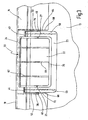
- the tool 20 further includes a U-shaped locking lever 23 which encloses the tab 22 and which is separated from the side edges and the lower edge of the tab 22 by a U-shaped recess 29. Opposite the two flange ends 68, 70, the securing lever 23 is separated at the edge by a respective slot-shaped recess 64, 66.
- the safety lever 23 is fixed at the upper end of the recesses 64, 66 at its two side edges via second hinges 43, 44 on the wall of the container 10 and the flange 14 pivotally.
- the second hinges 43, 44 are downwardly opposite the first hinge 24, i. arranged offset in the direction of the bottom 15 of the container, in the case shown by about 2 to 15 mm, preferably about 5 mm.
- the first and second hinges 24, 43, 44 are formed as film hinges, which are produced by a material weakening.
- the tool 20 is further provided with indicator elements 25, 27, which indicate a first relative movement of tab 22 and locking lever 23 to each other.
- indicator elements 25, 27 are provided as Abrißstege respectively on the left and on the right edge of the tab 22 and connect them via the U-shaped recess 29 with the locking lever 23rd
- the tab 22 is stiffened by a plurality of stiffeners 60 which extend from the lower edge of the tab 22 upwards and end shortly before the first hinge 24.
- the flange 14 is additionally supported by a plurality of support ribs on the wall 13. In FIG. 3 thereof are two support ribs 76, 78 in the region of the flange ends 68, 70, and three further support ribs 62 which extend from the upper edge 18 of the container 10 from down, recognizable. By this support ribs 62 a secure support of the first hinge 24 on the flange 14 and the edge 18 is ensured.
- the second hinges 43, 44, on which the securing lever 23 is fixed pivotably, are fixed directly on the flange 14 below the edge 18.
- the safety lever 23 is further characterized by stiffeners 58, 59, which on the second hinges 43; 44 start and run to near the lower edge of the safety lever 23, reinforced.
- the tab 22 and the locking lever 23 are completely adapted in their outer contour to the contour of the flange 14, as from the FIGS. 3 to 6 can be seen. Only the lower end of the tab 22 and the safety lever 23 is slightly downwardly opposite the lower edge of the flange 14.
- Fig. 4 the closed position of the container 10 with attached and latched lid 30 is shown.
- tab 22 and locking lever 23 in an aligned with the outer contour of the flange 14 position. If now the tool 20 are used to raise the lid edge 32 to the opening of the lid 30 partially in this area, so first the locking lever 23 must be pressed in the direction of the wall 13 of the container 10 out, the first time the indicator elements (tear-off webs) 25, 27 are destroyed (cf. Fig. 5 ).
- the safety lever 23 in this in Fig. 5 shown position via associated locking elements on the wall 13 to fix, if desired.
- a latching projection 46, 48 is integrally formed on the two flange ends 68, 70 facing edges of the safety lever 13, which protrudes toward the respective flange 68, 70 out.
- On the support ribs 76, 78 each have a thin, slightly protruding toward the locking lever 23 projecting locking bar 50, 52 is formed, which is set back in the direction of the wall 13 out that the locking lever 23 in the position according to Fig. 5 can be fixed by engaging behind the locking webs 50, 52 with the locking projections 46, 48.
- the tab 22 can be attacked from its lower edge and according to Fig. 6 be pivoted upward to raise the lid edge 32 so.
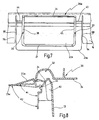
- FIGS. 7 and 8 is a respect to the execution according to the FIGS. 3 to 6 slightly modified embodiment of the invention shown, wherein the tool for lifting the lid edge is generally designated by the numeral 20a.
- the tab 22a is in turn fixed at its upper end by a first film hinge 24 on the container wall, while the securing lever 23a via second hinges 43, 44 which are offset relative to the first film hinge 24 down, is pivotally fixed.
- the locking lever 23a is separated from the flange ends 68, 70 by slot-shaped recesses 64, 66.
- the two side legs of the safety lever 23a are in turn connected via an indicator element 25, 27 in the form of a securing web with the tab 22a in combination.
- the tab 22a and the locking lever 23a move at different angles ⁇ 1 , and ⁇ 2 (see. Fig. 8 ), which is due to the different position of the first film hinge 24 and the second film hinges 43, 44.
- the locking lever 23a is connected to the lower edge of the tab 22a via the deformable member 37, which may simply be a material weakening or a kind of bellows.
- a deformable element 37 instead of a deformable element 37, a tearable element could also be provided.
- the indicator elements 25, 27 are provided only as additional display elements, which are not absolutely necessary.
- an inventive tool for partially lifting a patch on the container edge cover is shown in its entirety and designated overall by the numeral 20 d.
- the tool 20d has a tab 22d consisting of two tab segments, a first tab segment 100 on the right half of the tab 22d, and a second tab segment 101 on the left half of the tab 22d.
- the second tab segment 101 is fixed at its upper end in the vicinity of the upper edge 18 of the container via a film hinge 24.
- the second tab segment 101 is separated from the flange end 70 by a slot-shaped recess 66.
- the first tab segment 100 is connected at its upper edge 107 by a total of four securing elements 104 in the form of Abrißstegen with the flange 14, wherein this connection of the tab segment 100 is below the film hinge 24, with the second tab segment 101 in the vicinity of the upper edge 18 is attached.
- the two tab segments 100, 101 are connected to each other via a film hinge 102 which extends parallel to the two flange ends 68, 70 in the tab 22d to the lower edge thereof. Since the first tab segment 100 further from the flange 68 again by a slot-shaped recess 64 is separated, the first tab segment 100 can be pivoted about the formed as a film hinge pivot axes 102 toward the second tab segment 101, wherein the fuse elements 104 are torn open.
- the first tab segment 100 may be fully pivoted to and secured to the second tab segment 101 by inserting a locking pin 106 provided on the first tab segment 100 into an associated aperture 105 on the second tab segment 101. Subsequently, the unit formed from the two tab segments 100, 101 can be pivoted together about the film hinge 24 upwards in order to lift a lid placed in this area can. Conveniently, a perforation 103 is provided between the upper end of the film hinge 102 and the film hinge 24 in order to facilitate a pivoting up of the two tab segments 100, 101.
- the tool generally designated 20e has a tab 22e which interrupts the flange 14 in the region of the tool 20.
- the tab 22e is in its outer contour completely consistent with the outer contour of the flange 14 and is only slightly on its underside opposite the underside of the flange 14, as seen Fig. 12 can be seen.
- the tab 22e is articulated at its upper end in the immediate vicinity of the upper edge 18 of the container by means of a film hinge 24 on the flange 14.
- the film hinge 24, the in Fig. 13 only indicated by dashed lines, there is a weakening of material, whereby at this point pivoting is made possible.
- the tab 22e is separated at its two lateral transitions to the flange 14 in each case by a recess 64 or 66 from the respective end 68 or 70 of the flange 14.
- This recess 64 or 66 respectively runs in a horizontally widened recess 65 or 67.
- the tab 22e is respectively connected to the flange end 68 and 70 via a tearable web 72 and 74, through a further recess 71 and 73 at the bottom of the respective end 68 and 70 of the flange 14 is separated.
- the tab 22e has in its center a stiffener 60 for reinforcement.
- support ribs 62 are provided on the wall 13 of the container for supporting the pivot axis 24 and the film hinge.
- the flange itself is further supported against the wall by a plurality of support ribs, of which in Fig. 6 only the two support ribs 76 and 78 can be seen, which are formed at the ends 68 and 70 of the flange 14.
- FIGS. 14 and 15 A further modified embodiment of the tool for opening the container is in the FIGS. 14 and 15 represented and designated overall by the numeral 20f.
- the tab 22f is in turn pivotally received at its upper end on the film hinge 24. From the film hinge 24 run on both sides of the tab 22 f recesses 64 and 66, which completely separate the tab 22 f at their side edges of the respective ends of the flange 14.
- the display means for indicating the first pivoting of the flap 22f from a closed position to the outside is now no longer formed between the side edges of the flap 22f and the ends of the flange 14, but rather within the flap 22f at two locations.
- a support web 180 is provided, which extends from the film hinge 24 down and which is connected via a support rib 62 fixed to the wall 13 of the container.
- This support bar 180 is separated from the other areas of the tab 22f on both sides by a respective recess 181 or 182, which extends from the film hinge 24 down to the end of the support bar 180.
- a further recess 183 is provided in each case, are delimited by the two thin tearable webs 184 and 185, via which the support web 180 is connected to the remaining region of the tab 22 f.
Landscapes
- Engineering & Computer Science (AREA)
- Mechanical Engineering (AREA)
- Closures For Containers (AREA)
- Table Devices Or Equipment (AREA)
- Devices For Use In Laboratory Experiments (AREA)
Claims (14)
- Récipient doté d'un orifice (12) tourné vers le haut, sur le bord duquel est prévue une bride (14) périphérique qui est réalisée pour recevoir un couvercle (30) destiné à fermer le récipient, (i) la bride (14) étant interrompue dans au moins une zone par un outil (20) en formant deux extrémités de bride (68, 70), ou (ii) un outil (20d, 20f) étant disposé dans au moins une zone de la bride, l'outil présentant de plus une languette (22, 22a, 22d, 22f) articulée au récipient (10, 10b), laquelle est disposée de telle sorte qu'un couvercle (30) posé puisse être levé partiellement par un pivotement de la languette (22, 22a, 22d, 22f) vers l'extérieur dans la zone de l'outil (20, 20f) afin de faciliter une ouverture du couvercle (30),
caractérisé en ce
qu'un second élément est associé à la languette ou la languette présente un second segment et en ce que le second élément ou l'un des segments de languette coopère avec la paroi du récipient de telle sorte que(1) la languette (22, 22a) soit articulée à une première charnière (24) et soit entourée par un levier de blocage (23, 23a) qui peut être pivoté par rapport à la languette (22, 22a) et les deux extrémités de bride (68, 70), que le levier de blocage (23, 23a) soit fixé sur ses deux bords latéraux tournés vers les extrémités de bride par deux charnières (43, 44) sur la paroi (13) du récipient (10), et que les secondes charnières (43, 44) soient disposées en décalé par rapport à la première charnière (24) vers le bas en direction du fond (15) du récipient (10), et que la bride (14) soit interrompue dans au moins une zone par l'outil (20) en formant deux extrémités de bride (68, 70),
ou(2) la languette (22d) présente un premier segment de languette (100) qui est relié à pivotement à un second segment de languette (101) articulé au bord du récipient, et qui est fixé par au moins un élément d'arrêt (104) déchirable sur la paroi (13) du récipient dans une position de fermeture, et que la bride (14) soit interrompue dans au moins une zone par l'outil (20d) en formant deux extrémités de bride (68, 70),
ou(3) au moins un dispositif indicateur soit prévu sur la bride (22f) afin d'indiquer un premier pivotement de la languette (22f) vers l'extérieur, qu'au moins une traverse d'appui (180) fixée sur la paroi (13) du récipient (10, 10b) soit prévue, laquelle est reliée solidement à une partie de la languette (22f) qui est séparée par au moins un évidement (181, 182, 183, 185) du reste de la languette (22f), que la traverse d'appui (180) soit reliée par au moins un élément indicateur au reste de la languette (22f) de telle sorte qu'un premier pivotement de la languette (22f) vers l'extérieur entraîne un endommagement de l'élément indicateur, et que l'outil (20f) soit disposé dans au moins une zone de la bride. - Récipient selon la revendication 1, caractérisé en ce que le levier de blocage (23, 23a) est réalisé essentiellement en forme de U et est séparé de la bride (22, 22a) par un évidement (29) essentiellement en forme de U.
- Récipient selon la revendication 1 ou 2, caractérisé en ce que le levier de blocage (23, 23a) présente au moins un élément d'encliquetage (46, 48) qui coopère avec un contre-élément (50, 52) afin de fixer le levier de blocage (23, 23a) dans une position pivotée vers la paroi (13) du récipient.
- Récipient selon la revendication 3, caractérisé en ce que des saillies d'encliquetage (46, 48) qui coopèrent avec des traverses d'encliquetage (50, 52) reculées en direction de la paroi (13) du récipient, qui sont reçues par des nervures d'appui (76, 78) sur la paroi (13) du récipient, sont prévues sur les arêtes extérieures du levier de blocage (23) tournées vers les extrémités de bride (68, 70).
- Récipient selon la revendication 1, caractérisé en ce que le levier de blocage (23a) est réalisé essentiellement en forme de U et est relié dans sa zone médiane, inférieure à la languette (22a), est toutefois séparé sur ses deux branches latérales par des évidements (38, 40) des bords extérieurs de la languette (22a).
- Récipient selon la revendication 5, caractérisé en ce que le levier de blocage (23a) est relié dans sa zone médiane, inférieure par un élément (37) déformable ou un élément déchirable à la languette (22a).
- Récipient selon l'une quelconque des revendications précédentes, caractérisé en ce que le levier de blocage (23, 23a) est relié par au moins un élément indicateur (25, 27) à la languette (22, 22a) afin d'indiquer un premier mouvement relatif entre le levier de blocage (23, 23a) et la languette (22, 22a).
- Récipient selon l'une quelconque des revendications précédentes, caractérisé en ce que les premières et les secondes charnières (24, 43, 44) de la languette (22, 22a) et du levier de blocage (23, 23a) sont réalisées comme des charnières à film.
- Récipient selon la revendication 1, caractérisé en ce que le premier segment de languette (100) est fixé sur son bord supérieur par au moins une traverse d'arrêt (104) sur la paroi (13) du récipient et peut être pivoté après la rupture d'au moins une traverse d'arrêt (104) autour d'un axe de pivotement (102) approximativement parallèle aux extrémités de bride (68, 70) sur le second segment de languette (101).
- Récipient selon la revendication 9, caractérisé en ce que sur le premier et le second segments de languette (100, 101) sont prévus des éléments de retenue (105, 106) associés l'un à l'autre, qui permettent une fixation du premier segment de languette (100) sur le second segment de languette (101) .
- Récipient selon la revendication 10, caractérisé en ce qu'un orifice (105) est prévu sur l'un des segments de languette (100) et une goupille de sécurité (106) associée, pouvant être fixée dans l'orifice est prévue sur l'autre segment de languette (101).
- Récipient selon l'une quelconque des revendications 1 à 11, caractérisé en ce que la languette (22, 22a, 22b, 22c, 22d) dans la mesure où celle-ci est entourée par un levier de blocage (23, 23a) ou présente un premier et un second segments de languette (100,101), et/ou le levier de blocage (23, 23a) sont adaptés essentiellement au contour de la bride (14) ou sont réalisés essentiellement dans le contour de la bride (14).
- Récipient selon l'une quelconque des revendications 1 à 12, caractérisé en ce que le récipient est réalisé pour recevoir le couvercle (30) destiné à fermer le récipient par encliquetage.
- Récipient selon la revendication 1, caractérisé en ce que la traverse d'appui (180) est séparée par des évidements (181, 182) s'étendant à peu près depuis un axe de pivotement (24) supérieur de la languette (22) vers le bas de la zone restante de la languette (22), et en ce qu'au moins un élément indicateur est formé sous la forme d'une traverse (184, 185) déchirable entre la traverse d'appui (180) et la zone restante de la languette (22) par un autre évidement (183) associé dans la languette (22).
Priority Applications (2)
| Application Number | Priority Date | Filing Date | Title |
|---|---|---|---|
| EP06011918A EP1724202B1 (fr) | 2001-08-07 | 2002-08-01 | Récipient avec couvercle |
| CY20091100443T CY1108989T1 (el) | 2001-08-07 | 2009-04-14 | Δοχειο με καλυμμα |
Applications Claiming Priority (7)
| Application Number | Priority Date | Filing Date | Title |
|---|---|---|---|
| DE10140255 | 2001-08-07 | ||
| DE10140255A DE10140255A1 (de) | 2001-08-07 | 2001-08-07 | Behälter mit Deckel |
| DE10150390A DE10150390C1 (de) | 2001-10-08 | 2001-10-08 | Behälter mit Deckel |
| DE10150390 | 2001-10-08 | ||
| DE20119701U | 2001-11-29 | ||
| DE20119701U DE20119701U1 (de) | 2001-08-07 | 2001-11-29 | Behälter mit Deckel |
| PCT/EP2002/008571 WO2003013967A1 (fr) | 2001-08-07 | 2002-08-01 | Recipient muni de son couvercle |
Related Child Applications (1)
| Application Number | Title | Priority Date | Filing Date |
|---|---|---|---|
| EP06011918A Division EP1724202B1 (fr) | 2001-08-07 | 2002-08-01 | Récipient avec couvercle |
Publications (2)
| Publication Number | Publication Date |
|---|---|
| EP1414708A1 EP1414708A1 (fr) | 2004-05-06 |
| EP1414708B1 true EP1414708B1 (fr) | 2009-01-21 |
Family
ID=27214565
Family Applications (2)
| Application Number | Title | Priority Date | Filing Date |
|---|---|---|---|
| EP02779256A Expired - Lifetime EP1414708B1 (fr) | 2001-08-07 | 2002-08-01 | Recipient muni de son couvercle |
| EP06011918A Expired - Lifetime EP1724202B1 (fr) | 2001-08-07 | 2002-08-01 | Récipient avec couvercle |
Family Applications After (1)
| Application Number | Title | Priority Date | Filing Date |
|---|---|---|---|
| EP06011918A Expired - Lifetime EP1724202B1 (fr) | 2001-08-07 | 2002-08-01 | Récipient avec couvercle |
Country Status (8)
| Country | Link |
|---|---|
| EP (2) | EP1414708B1 (fr) |
| AT (2) | ATE411231T1 (fr) |
| CY (2) | CY1108899T1 (fr) |
| DE (3) | DE20119701U1 (fr) |
| DK (2) | DK1414708T3 (fr) |
| ES (2) | ES2320741T3 (fr) |
| PT (2) | PT1724202E (fr) |
| WO (1) | WO2003013967A1 (fr) |
Families Citing this family (62)
| Publication number | Priority date | Publication date | Assignee | Title |
|---|---|---|---|---|
| DE10210486A1 (de) * | 2002-03-11 | 2003-10-09 | Jokey Plastik Gummersbach Gmbh | Behälter mit Deckel |
| US10226376B2 (en) | 2014-03-19 | 2019-03-12 | Purewick Corporation | Apparatus and methods for receiving discharged urine |
| US10390989B2 (en) | 2014-03-19 | 2019-08-27 | Purewick Corporation | Apparatus and methods for receiving discharged urine |
| US10952889B2 (en) | 2016-06-02 | 2021-03-23 | Purewick Corporation | Using wicking material to collect liquid for transport |
| US11806266B2 (en) | 2014-03-19 | 2023-11-07 | Purewick Corporation | Apparatus and methods for receiving discharged urine |
| US11376152B2 (en) | 2014-03-19 | 2022-07-05 | Purewick Corporation | Apparatus and methods for receiving discharged urine |
| AU2015341707B2 (en) | 2014-11-07 | 2019-12-19 | Rpc Superfos A/S | Lid lever for container |
| DE202015105350U1 (de) * | 2015-10-09 | 2017-01-11 | Jokey Plastik Wipperfürth GmbH | Behälter mit Deckel |
| US10973678B2 (en) | 2016-07-27 | 2021-04-13 | Purewick Corporation | Apparatus and methods for receiving discharged urine |
| US10376406B2 (en) | 2016-07-27 | 2019-08-13 | Purewick Corporation | Male urine collection device using wicking material |
| WO2018144463A1 (fr) | 2017-01-31 | 2018-08-09 | Purewick Corporation | Appareil et procédés pour la réception d'urine excrétée |
| EP3787571B1 (fr) | 2018-05-01 | 2022-06-01 | Purewick Corporation | Vêtements de collecte de fluide |
| JP7072084B2 (ja) | 2018-05-01 | 2022-05-19 | ピュアウィック コーポレイション | 流体収集装置、関連システム、及び関連方法 |
| EP3787569B1 (fr) | 2018-05-01 | 2025-07-16 | Purewick Corporation | Dispositifs et systèmes de collecte de fluide |
| AU2019262939A1 (en) | 2018-05-01 | 2020-11-26 | Purewick Corporation | Fluid collection devices, systems, and methods |
| AU2019262945B2 (en) | 2018-05-01 | 2022-08-25 | Purewick Corporation | Fluid collection devices and methods of using the same |
| US11944740B2 (en) | 2018-05-01 | 2024-04-02 | Purewick Corporation | Fluid collection devices, related systems, and related methods |
| CA3143904C (fr) | 2019-06-21 | 2023-11-28 | Purewick Corporation | Dispositifs de collecte de fluide comprenant une zone de fixation de base, et systemes et procedes associes |
| ES2961269T3 (es) | 2019-07-11 | 2024-03-11 | Purewick Corp | Dispositivos y sistemas de recogida de líquido |
| WO2021016026A1 (fr) | 2019-07-19 | 2021-01-28 | Purewick Corporation | Dispositifs de collecte de fluide comprenant au moins un matériau à mémoire de forme |
| EP4051190B1 (fr) | 2019-10-28 | 2024-05-22 | Purewick Corporation | Ensembles de collecte de fluide comprenant un orifice d'échantillon |
| EP4559443A3 (fr) | 2020-01-03 | 2025-06-18 | Purewick Corporation | Dispositifs de collecte d'urine ayant une partie relativement large et une partie allongée et procédés associés |
| WO2021188817A1 (fr) | 2020-03-19 | 2021-09-23 | Purewick Corporation | Ensembles de collecte de fluide comprenant un ou plusieurs éléments d'amélioration du mouvement |
| US12521288B2 (en) | 2020-03-26 | 2026-01-13 | Purewick Corporation | Multi-layer urine capture device and related methods |
| WO2021207621A1 (fr) | 2020-04-10 | 2021-10-14 | Purewick Corporation | Ensembles de collecte de fluide comprenant un ou plusieurs éléments de prévention de fuite |
| WO2021211801A1 (fr) | 2020-04-17 | 2021-10-21 | Purewick Corporation | Ensembles de collecte de fluide comprenant une barrière imperméable aux fluides comportant une cuvette et une base |
| US12465514B2 (en) | 2020-04-17 | 2025-11-11 | Purewick Corporation | Fluid collection devices, systems, and methods securing a protruding portion in position for use |
| US12472090B2 (en) | 2020-04-17 | 2025-11-18 | Purewick Corporation | Female external catheter devices having a urethral cup, and related systems and methods |
| US12491104B2 (en) | 2020-04-20 | 2025-12-09 | Purewick Corporation | Fluid collection devices adjustable between a vacuum-based orientation and a gravity-based orientation, and related systems and methods |
| US12048643B2 (en) | 2020-05-27 | 2024-07-30 | Purewick Corporation | Fluid collection assemblies including at least one inflation device and methods and systems of using the same |
| USD967409S1 (en) | 2020-07-15 | 2022-10-18 | Purewick Corporation | Urine collection apparatus cover |
| US12440371B2 (en) | 2020-08-06 | 2025-10-14 | Purewick Corporation | Fluid collection system including a garment and a fluid collection device |
| US12350187B2 (en) | 2020-08-11 | 2025-07-08 | Purewick Corporation | Fluid collection assemblies defining waist and leg openings |
| EP4210643A1 (fr) | 2020-09-09 | 2023-07-19 | Purewick Corporation | Dispositifs, systèmes et procédés de collecte de fluide |
| US12156792B2 (en) | 2020-09-10 | 2024-12-03 | Purewick Corporation | Fluid collection assemblies including at least one inflation device |
| US11801186B2 (en) | 2020-09-10 | 2023-10-31 | Purewick Corporation | Urine storage container handle and lid accessories |
| US12042423B2 (en) | 2020-10-07 | 2024-07-23 | Purewick Corporation | Fluid collection systems including at least one tensioning element |
| US12208031B2 (en) | 2020-10-21 | 2025-01-28 | Purewick Corporation | Adapters for fluid collection devices |
| US12257174B2 (en) | 2020-10-21 | 2025-03-25 | Purewick Corporation | Fluid collection assemblies including at least one of a protrusion or at least one expandable material |
| US12569365B2 (en) | 2020-10-21 | 2026-03-10 | Purewick Corporation | Fluid collection assemblies including at least one shape memory material disposed in the conduit |
| US12440370B2 (en) | 2020-10-21 | 2025-10-14 | Purewick Corporation | Apparatus with compressible casing for receiving discharged urine |
| US12048644B2 (en) | 2020-11-03 | 2024-07-30 | Purewick Corporation | Apparatus for receiving discharged urine |
| US12070432B2 (en) | 2020-11-11 | 2024-08-27 | Purewick Corporation | Urine collection system including a flow meter and related methods |
| US12245967B2 (en) | 2020-11-18 | 2025-03-11 | Purewick Corporation | Fluid collection assemblies including an adjustable spine |
| US12599495B2 (en) | 2021-01-05 | 2026-04-14 | Purewick Corporation | Male external catheter with attachment interface configured to bias against penis |
| US12268627B2 (en) | 2021-01-06 | 2025-04-08 | Purewick Corporation | Fluid collection assemblies including at least one securement body |
| JP2024503636A (ja) | 2021-01-07 | 2024-01-26 | ピュアウィック コーポレイション | 車椅子に固定可能な尿収集システムおよび関連する方法 |
| EP4349306A3 (fr) | 2021-01-19 | 2024-06-05 | Purewick Corporation | Dispositifs, systèmes et procédés de collecte de fluide à ajustement variable |
| US12178735B2 (en) | 2021-02-09 | 2024-12-31 | Purewick Corporation | Noise reduction for a urine suction system |
| EP4274524B1 (fr) | 2021-02-26 | 2024-08-28 | Purewick Corporation | Dispositif de collecte de fluide configuré comme un dispositif de collecte d'urine masculin |
| US12551385B2 (en) | 2021-03-05 | 2026-02-17 | Purewick Corporation | Fluid collection assembly including a tube having porous wicking material for improved fluid transport |
| US12558472B2 (en) | 2021-03-05 | 2026-02-24 | Purewick Corporation | Portable fluid collection systems with storage and related methods |
| US12458525B2 (en) | 2021-03-10 | 2025-11-04 | Purewick Corporation | Acoustic silencer for a urine suction system |
| US11938054B2 (en) | 2021-03-10 | 2024-03-26 | Purewick Corporation | Bodily waste and fluid collection with sacral pad |
| US12029677B2 (en) | 2021-04-06 | 2024-07-09 | Purewick Corporation | Fluid collection devices having a collection bag, and related systems and methods |
| US12233003B2 (en) | 2021-04-29 | 2025-02-25 | Purewick Corporation | Fluid collection assemblies including at least one length adjusting feature |
| US12251333B2 (en) | 2021-05-21 | 2025-03-18 | Purewick Corporation | Fluid collection assemblies including at least one inflation device and methods and systems of using the same |
| US12324767B2 (en) | 2021-05-24 | 2025-06-10 | Purewick Corporation | Fluid collection assembly including a customizable external support and related methods |
| US12150885B2 (en) | 2021-05-26 | 2024-11-26 | Purewick Corporation | Fluid collection system including a cleaning system and methods |
| US12575960B2 (en) | 2021-06-24 | 2026-03-17 | Purewick Corporation | Urine collection systems having one or more of volume, pressure, or flow indicators, and related methods |
| US12551366B2 (en) | 2021-08-02 | 2026-02-17 | Purewick Corporation | Fluid collection devices having multiple fluid collection regions, and related systems and methods |
| US12594062B2 (en) | 2021-09-08 | 2026-04-07 | Purewick Corporation | Fluid collection assemblies including an extension |
Family Cites Families (6)
| Publication number | Priority date | Publication date | Assignee | Title |
|---|---|---|---|---|
| DE9205256U1 (de) * | 1992-04-15 | 1992-06-17 | Saier GmbH & Co., 7297 Alpirsbach | Topfförmiges Gefäß, insbesondere Eimer o.dgl. |
| FR2745270B1 (fr) * | 1996-02-22 | 2000-04-28 | Nicot Christian | Emballage muni de moyens formant un temoin d'inviolabilite |
| NL1005099C2 (nl) * | 1997-01-27 | 1998-07-29 | Den Brink B V Van | Kunststof emmer met deksel en verzegelingslip. |
| US5873482A (en) * | 1997-12-19 | 1999-02-23 | Plastican, Inc. | Tamper-evident container closure |
| DE29822727U1 (de) * | 1998-12-21 | 1999-02-18 | Saier GmbH & Co., 72275 Alpirsbach | Topfförmiges Gefäß, insbesondere Eimer o.dgl. |
| SE522764C2 (sv) * | 2000-02-04 | 2004-03-02 | Emballator Lagan Plast Ab | Behållare med lock |
-
2001
- 2001-11-29 DE DE20119701U patent/DE20119701U1/de not_active Expired - Lifetime
-
2002
- 2002-08-01 DK DK02779256T patent/DK1414708T3/da active
- 2002-08-01 EP EP02779256A patent/EP1414708B1/fr not_active Expired - Lifetime
- 2002-08-01 EP EP06011918A patent/EP1724202B1/fr not_active Expired - Lifetime
- 2002-08-01 DE DE50213239T patent/DE50213239D1/de not_active Expired - Lifetime
- 2002-08-01 PT PT06011918T patent/PT1724202E/pt unknown
- 2002-08-01 AT AT06011918T patent/ATE411231T1/de active
- 2002-08-01 DE DE50212922T patent/DE50212922D1/de not_active Expired - Lifetime
- 2002-08-01 DK DK06011918T patent/DK1724202T3/da active
- 2002-08-01 WO PCT/EP2002/008571 patent/WO2003013967A1/fr not_active Ceased
- 2002-08-01 AT AT02779256T patent/ATE421463T1/de active
- 2002-08-01 ES ES02779256T patent/ES2320741T3/es not_active Expired - Lifetime
- 2002-08-01 ES ES06011918T patent/ES2315963T3/es not_active Expired - Lifetime
- 2002-08-01 PT PT02779256T patent/PT1414708E/pt unknown
-
2009
- 2009-01-09 CY CY20091100014T patent/CY1108899T1/el unknown
- 2009-04-14 CY CY20091100443T patent/CY1108989T1/el unknown
Also Published As
| Publication number | Publication date |
|---|---|
| PT1724202E (pt) | 2009-01-14 |
| DE50212922D1 (de) | 2008-11-27 |
| CY1108899T1 (el) | 2014-07-02 |
| DK1724202T3 (da) | 2009-02-16 |
| CY1108989T1 (el) | 2014-07-02 |
| ES2320741T3 (es) | 2009-05-28 |
| DE20119701U1 (de) | 2002-12-19 |
| EP1414708A1 (fr) | 2004-05-06 |
| WO2003013967A1 (fr) | 2003-02-20 |
| DK1414708T3 (da) | 2009-05-18 |
| PT1414708E (pt) | 2009-04-24 |
| ATE421463T1 (de) | 2009-02-15 |
| DE50213239D1 (de) | 2009-03-12 |
| EP1724202A1 (fr) | 2006-11-22 |
| ES2315963T3 (es) | 2009-04-01 |
| ATE411231T1 (de) | 2008-10-15 |
| EP1724202B1 (fr) | 2008-10-15 |
Similar Documents
| Publication | Publication Date | Title |
|---|---|---|
| EP1414708B1 (fr) | Recipient muni de son couvercle | |
| DE69005109T2 (de) | Wiederverschliessbarer deckel mit originalitätssicherung. | |
| EP1747151B1 (fr) | Couvercle à l' épreuve des manipulations | |
| EP2670683B1 (fr) | Fermeture sous forme de bouchon à charnière, pourvue d'une partie d'actionnement et d'un indicateur d'effraction | |
| CH658634A5 (de) | Behaelter mit deckel. | |
| DE69520572T2 (de) | Öffnungseinrichtung für die ausgussabdichtung eines flüssigkeitsbehälters | |
| DE69606050T2 (de) | Behälter,insbesondere getränkedose | |
| DE3323009A1 (de) | Aufreissdeckel aus blech | |
| DE3009513A1 (de) | Verschlussystem | |
| DE202007008781U1 (de) | Behälter | |
| DE2720860C2 (de) | Aufreißdeckel aus Blech | |
| DE2428395A1 (de) | Leicht zu oeffnender behaelter | |
| DE3607402C2 (fr) | ||
| DE1432130A1 (de) | Deckel fuer Dosen oder dergleichen Behaelter mit durch Schwaechungslinien begrenzten Aufreissstreifen | |
| DE2348648C3 (de) | Endwand für eine Dose | |
| DE4334486C2 (de) | Kunststoffbehälter mit aufrastbarem Deckel | |
| DE2117864A1 (de) | Vorrichtung zum Offnen eines mit einer Anriss oder Schwächungslinie versehenen Metalldeckels fur Behalter, insbesondere Konserven | |
| EP1414709A1 (fr) | Recipient a couvercle | |
| DE102018133278A1 (de) | Getränkedose | |
| DE19712364A1 (de) | Schnappverschluß | |
| EP3566775B1 (fr) | Pile de cassettes composée de cassettes individuelles, de préférence destinée à la réception des préparations pour analyses de laboratoire | |
| EP3504129A1 (fr) | Fermeture à déclic à élément d'inviolabilité | |
| EP1281627A2 (fr) | Ensemble de fermeture de récipient avec garantie d'inviolabilité | |
| DE10150390C1 (de) | Behälter mit Deckel | |
| EP0788975A1 (fr) | Capuchon de sécurité et de protection pour orifices de récipient |
Legal Events
| Date | Code | Title | Description |
|---|---|---|---|
| PUAI | Public reference made under article 153(3) epc to a published international application that has entered the european phase |
Free format text: ORIGINAL CODE: 0009012 |
|
| 17P | Request for examination filed |
Effective date: 20040114 |
|
| AK | Designated contracting states |
Kind code of ref document: A1 Designated state(s): AT BE BG CH CY CZ DE DK EE ES FI FR GB GR IE IT LI LU MC NL PT SE SK TR |
|
| AX | Request for extension of the european patent |
Extension state: AL LT LV MK RO SI |
|
| RIN1 | Information on inventor provided before grant (corrected) |
Inventor name: HAEHNLE, THOMAS Inventor name: FISCHER, RONALD Inventor name: HEINZELMANN, ACHIM Inventor name: BATSCHIED, KARL |
|
| RAP1 | Party data changed (applicant data changed or rights of an application transferred) |
Owner name: JOKEY PLASTIK GUMMERSBACH GMBH |
|
| 17Q | First examination report despatched |
Effective date: 20060216 |
|
| 17Q | First examination report despatched |
Effective date: 20060216 |
|
| GRAP | Despatch of communication of intention to grant a patent |
Free format text: ORIGINAL CODE: EPIDOSNIGR1 |
|
| GRAS | Grant fee paid |
Free format text: ORIGINAL CODE: EPIDOSNIGR3 |
|
| GRAA | (expected) grant |
Free format text: ORIGINAL CODE: 0009210 |
|
| AK | Designated contracting states |
Kind code of ref document: B1 Designated state(s): AT BE BG CH CY CZ DE DK EE ES FI FR GB GR IE IT LI LU MC NL PT SE SK TR |
|
| REG | Reference to a national code |
Ref country code: GB Ref legal event code: FG4D Free format text: NOT ENGLISH |
|
| REG | Reference to a national code |
Ref country code: CH Ref legal event code: EP |
|
| REG | Reference to a national code |
Ref country code: IE Ref legal event code: FG4D Free format text: LANGUAGE OF EP DOCUMENT: GERMAN |
|
| REF | Corresponds to: |
Ref document number: 50213239 Country of ref document: DE Date of ref document: 20090312 Kind code of ref document: P |
|
| REG | Reference to a national code |
Ref country code: SE Ref legal event code: TRGR |
|
| REG | Reference to a national code |
Ref country code: PT Ref legal event code: SC4A Free format text: AVAILABILITY OF NATIONAL TRANSLATION Effective date: 20090416 |
|
| REG | Reference to a national code |
Ref country code: CH Ref legal event code: NV Representative=s name: KATZAROV S.A. Ref country code: GR Ref legal event code: EP Ref document number: 20090400972 Country of ref document: GR |
|
| REG | Reference to a national code |
Ref country code: DK Ref legal event code: T3 |
|
| REG | Reference to a national code |
Ref country code: ES Ref legal event code: FG2A Ref document number: 2320741 Country of ref document: ES Kind code of ref document: T3 |
|
| PLBE | No opposition filed within time limit |
Free format text: ORIGINAL CODE: 0009261 |
|
| STAA | Information on the status of an ep patent application or granted ep patent |
Free format text: STATUS: NO OPPOSITION FILED WITHIN TIME LIMIT |
|
| 26N | No opposition filed |
Effective date: 20091022 |
|
| PGFP | Annual fee paid to national office [announced via postgrant information from national office to epo] |
Ref country code: CY Payment date: 20100726 Year of fee payment: 9 |
|
| PGFP | Annual fee paid to national office [announced via postgrant information from national office to epo] |
Ref country code: LU Payment date: 20110824 Year of fee payment: 10 |
|
| PGFP | Annual fee paid to national office [announced via postgrant information from national office to epo] |
Ref country code: BG Payment date: 20110824 Year of fee payment: 10 Ref country code: MC Payment date: 20110823 Year of fee payment: 10 Ref country code: DK Payment date: 20110824 Year of fee payment: 10 Ref country code: IE Payment date: 20110819 Year of fee payment: 10 Ref country code: CH Payment date: 20110824 Year of fee payment: 10 |
|
| PGFP | Annual fee paid to national office [announced via postgrant information from national office to epo] |
Ref country code: TR Payment date: 20110720 Year of fee payment: 10 Ref country code: CZ Payment date: 20110720 Year of fee payment: 10 Ref country code: PT Payment date: 20110721 Year of fee payment: 10 Ref country code: FR Payment date: 20110829 Year of fee payment: 10 Ref country code: SE Payment date: 20110823 Year of fee payment: 10 Ref country code: AT Payment date: 20110822 Year of fee payment: 10 Ref country code: GR Payment date: 20110823 Year of fee payment: 10 Ref country code: SK Payment date: 20110726 Year of fee payment: 10 Ref country code: ES Payment date: 20110825 Year of fee payment: 10 Ref country code: EE Payment date: 20110823 Year of fee payment: 10 Ref country code: FI Payment date: 20110822 Year of fee payment: 10 Ref country code: GB Payment date: 20110824 Year of fee payment: 10 |
|
| PGFP | Annual fee paid to national office [announced via postgrant information from national office to epo] |
Ref country code: IT Payment date: 20110824 Year of fee payment: 10 Ref country code: NL Payment date: 20110825 Year of fee payment: 10 Ref country code: BE Payment date: 20110822 Year of fee payment: 10 |
|
| REG | Reference to a national code |
Ref country code: PT Ref legal event code: MM4A Free format text: LAPSE DUE TO NON-PAYMENT OF FEES Effective date: 20130201 |
|
| BERE | Be: lapsed |
Owner name: JOKEY PLASTIK GUMMERSBACH G.M.B.H. Effective date: 20120831 |
|
| REG | Reference to a national code |
Ref country code: NL Ref legal event code: V1 Effective date: 20130301 |
|
| REG | Reference to a national code |
Ref country code: CH Ref legal event code: PL |
|
| PG25 | Lapsed in a contracting state [announced via postgrant information from national office to epo] |
Ref country code: MC Free format text: LAPSE BECAUSE OF NON-PAYMENT OF DUE FEES Effective date: 20120831 |
|
| REG | Reference to a national code |
Ref country code: SE Ref legal event code: EUG Ref country code: DK Ref legal event code: EBP |
|
| REG | Reference to a national code |
Ref country code: EE Ref legal event code: MM4A Ref document number: E003092 Country of ref document: EE Effective date: 20120831 Ref country code: AT Ref legal event code: MM01 Ref document number: 421463 Country of ref document: AT Kind code of ref document: T Effective date: 20120801 |
|
| GBPC | Gb: european patent ceased through non-payment of renewal fee |
Effective date: 20120801 |
|
| PG25 | Lapsed in a contracting state [announced via postgrant information from national office to epo] |
Ref country code: SE Free format text: LAPSE BECAUSE OF NON-PAYMENT OF DUE FEES Effective date: 20120802 Ref country code: CZ Free format text: LAPSE BECAUSE OF NON-PAYMENT OF DUE FEES Effective date: 20120801 Ref country code: NL Free format text: LAPSE BECAUSE OF NON-PAYMENT OF DUE FEES Effective date: 20130301 Ref country code: CH Free format text: LAPSE BECAUSE OF NON-PAYMENT OF DUE FEES Effective date: 20120831 Ref country code: FI Free format text: LAPSE BECAUSE OF NON-PAYMENT OF DUE FEES Effective date: 20120801 Ref country code: LI Free format text: LAPSE BECAUSE OF NON-PAYMENT OF DUE FEES Effective date: 20120831 Ref country code: EE Free format text: LAPSE BECAUSE OF NON-PAYMENT OF DUE FEES Effective date: 20120831 |
|
| REG | Reference to a national code |
Ref country code: GR Ref legal event code: ML Ref document number: 20090400972 Country of ref document: GR Effective date: 20130304 |
|
| REG | Reference to a national code |
Ref country code: SK Ref legal event code: MM4A Ref document number: E 5372 Country of ref document: SK Effective date: 20120801 |
|
| REG | Reference to a national code |
Ref country code: FR Ref legal event code: ST Effective date: 20130430 |
|
| REG | Reference to a national code |
Ref country code: IE Ref legal event code: MM4A |
|
| PG25 | Lapsed in a contracting state [announced via postgrant information from national office to epo] |
Ref country code: PT Free format text: LAPSE BECAUSE OF NON-PAYMENT OF DUE FEES Effective date: 20130201 Ref country code: CY Free format text: LAPSE BECAUSE OF NON-PAYMENT OF DUE FEES Effective date: 20120801 Ref country code: SK Free format text: LAPSE BECAUSE OF NON-PAYMENT OF DUE FEES Effective date: 20120801 Ref country code: GR Free format text: LAPSE BECAUSE OF NON-PAYMENT OF DUE FEES Effective date: 20130304 Ref country code: IT Free format text: LAPSE BECAUSE OF NON-PAYMENT OF DUE FEES Effective date: 20120801 Ref country code: BE Free format text: LAPSE BECAUSE OF NON-PAYMENT OF DUE FEES Effective date: 20120831 |
|
| PG25 | Lapsed in a contracting state [announced via postgrant information from national office to epo] |
Ref country code: AT Free format text: LAPSE BECAUSE OF NON-PAYMENT OF DUE FEES Effective date: 20120801 |
|
| PG25 | Lapsed in a contracting state [announced via postgrant information from national office to epo] |
Ref country code: DK Free format text: LAPSE BECAUSE OF NON-PAYMENT OF DUE FEES Effective date: 20120831 Ref country code: IE Free format text: LAPSE BECAUSE OF NON-PAYMENT OF DUE FEES Effective date: 20120801 Ref country code: GB Free format text: LAPSE BECAUSE OF NON-PAYMENT OF DUE FEES Effective date: 20120801 |
|
| PG25 | Lapsed in a contracting state [announced via postgrant information from national office to epo] |
Ref country code: FR Free format text: LAPSE BECAUSE OF NON-PAYMENT OF DUE FEES Effective date: 20120831 |
|
| REG | Reference to a national code |
Ref country code: ES Ref legal event code: FD2A Effective date: 20131030 |
|
| PG25 | Lapsed in a contracting state [announced via postgrant information from national office to epo] |
Ref country code: ES Free format text: LAPSE BECAUSE OF NON-PAYMENT OF DUE FEES Effective date: 20120802 |
|
| PG25 | Lapsed in a contracting state [announced via postgrant information from national office to epo] |
Ref country code: TR Free format text: LAPSE BECAUSE OF NON-PAYMENT OF DUE FEES Effective date: 20120801 |
|
| PG25 | Lapsed in a contracting state [announced via postgrant information from national office to epo] |
Ref country code: LU Free format text: LAPSE BECAUSE OF NON-PAYMENT OF DUE FEES Effective date: 20120801 |
|
| PG25 | Lapsed in a contracting state [announced via postgrant information from national office to epo] |
Ref country code: BG Free format text: LAPSE BECAUSE OF NON-PAYMENT OF DUE FEES Effective date: 20120831 |
|
| PGFP | Annual fee paid to national office [announced via postgrant information from national office to epo] |
Ref country code: DE Payment date: 20211027 Year of fee payment: 20 |
|
| REG | Reference to a national code |
Ref country code: DE Ref legal event code: R071 Ref document number: 50213239 Country of ref document: DE |