EP1415054B1 - Bloc desinfectant fixe sur le rebord d'une toilette avec plaque d'extension - Google Patents
Bloc desinfectant fixe sur le rebord d'une toilette avec plaque d'extension Download PDFInfo
- Publication number
- EP1415054B1 EP1415054B1 EP03765605A EP03765605A EP1415054B1 EP 1415054 B1 EP1415054 B1 EP 1415054B1 EP 03765605 A EP03765605 A EP 03765605A EP 03765605 A EP03765605 A EP 03765605A EP 1415054 B1 EP1415054 B1 EP 1415054B1
- Authority
- EP
- European Patent Office
- Prior art keywords
- extension plate
- base
- toilet
- wicking device
- wicking
- Prior art date
- Legal status (The legal status is an assumption and is not a legal conclusion. Google has not performed a legal analysis and makes no representation as to the accuracy of the status listed.)
- Expired - Lifetime
Links
- 239000007788 liquid Substances 0.000 claims abstract description 100
- XLYOFNOQVPJJNP-UHFFFAOYSA-N water Substances O XLYOFNOQVPJJNP-UHFFFAOYSA-N 0.000 claims abstract description 77
- 238000002360 preparation method Methods 0.000 claims abstract description 7
- 239000012530 fluid Substances 0.000 claims description 14
- 239000000725 suspension Substances 0.000 claims description 10
- 238000004891 communication Methods 0.000 claims description 4
- 238000004140 cleaning Methods 0.000 description 22
- 238000011010 flushing procedure Methods 0.000 description 14
- 239000013543 active substance Substances 0.000 description 6
- -1 polyethylene Polymers 0.000 description 6
- 239000007787 solid Substances 0.000 description 6
- 239000000203 mixture Substances 0.000 description 5
- 238000005406 washing Methods 0.000 description 4
- 239000004698 Polyethylene Substances 0.000 description 3
- 239000004743 Polypropylene Substances 0.000 description 3
- 239000003945 anionic surfactant Substances 0.000 description 3
- 238000009434 installation Methods 0.000 description 3
- 238000004519 manufacturing process Methods 0.000 description 3
- 239000002736 nonionic surfactant Substances 0.000 description 3
- 229920000573 polyethylene Polymers 0.000 description 3
- 229920001155 polypropylene Polymers 0.000 description 3
- 239000002904 solvent Substances 0.000 description 3
- 239000012815 thermoplastic material Substances 0.000 description 3
- 239000003795 chemical substances by application Substances 0.000 description 2
- 239000000975 dye Substances 0.000 description 2
- 239000003205 fragrance Substances 0.000 description 2
- 238000003780 insertion Methods 0.000 description 2
- 230000037431 insertion Effects 0.000 description 2
- 239000003755 preservative agent Substances 0.000 description 2
- 238000005201 scrubbing Methods 0.000 description 2
- 239000002562 thickening agent Substances 0.000 description 2
- 241000894006 Bacteria Species 0.000 description 1
- 230000004075 alteration Effects 0.000 description 1
- 125000000129 anionic group Chemical group 0.000 description 1
- 239000012459 cleaning agent Substances 0.000 description 1
- 230000007423 decrease Effects 0.000 description 1
- 230000001877 deodorizing effect Effects 0.000 description 1
- 230000000249 desinfective effect Effects 0.000 description 1
- 238000009826 distribution Methods 0.000 description 1
- 238000005315 distribution function Methods 0.000 description 1
- 238000001704 evaporation Methods 0.000 description 1
- 230000008020 evaporation Effects 0.000 description 1
- 238000005187 foaming Methods 0.000 description 1
- 239000011888 foil Substances 0.000 description 1
- 230000005484 gravity Effects 0.000 description 1
- 230000001939 inductive effect Effects 0.000 description 1
- 239000000463 material Substances 0.000 description 1
- 235000019645 odor Nutrition 0.000 description 1
- 239000002245 particle Substances 0.000 description 1
- 239000002304 perfume Substances 0.000 description 1
- 239000002985 plastic film Substances 0.000 description 1
- 229920006255 plastic film Polymers 0.000 description 1
- 230000002335 preservative effect Effects 0.000 description 1
- 238000009877 rendering Methods 0.000 description 1
- 238000011012 sanitization Methods 0.000 description 1
- 238000007789 sealing Methods 0.000 description 1
- 238000003860 storage Methods 0.000 description 1
- 239000000126 substance Substances 0.000 description 1
- 239000004094 surface-active agent Substances 0.000 description 1
- 229920001169 thermoplastic Polymers 0.000 description 1
- 239000004416 thermosoftening plastic Substances 0.000 description 1
- 229920006352 transparent thermoplastic Polymers 0.000 description 1
Images


Classifications
-
- E—FIXED CONSTRUCTIONS
- E03—WATER SUPPLY; SEWERAGE
- E03D—WATER-CLOSETS OR URINALS WITH FLUSHING DEVICES; FLUSHING VALVES THEREFOR
- E03D9/00—Sanitary or other accessories for lavatories ; Devices for cleaning or disinfecting the toilet room or the toilet bowl; Devices for eliminating smells
- E03D9/02—Devices adding a disinfecting, deodorising, or cleaning agent to the water while flushing
- E03D9/03—Devices adding a disinfecting, deodorising, or cleaning agent to the water while flushing consisting of a separate container with an outlet through which the agent is introduced into the flushing water, e.g. by suction ; Devices for agents in direct contact with flushing water
- E03D9/032—Devices connected to or dispensing into the bowl
Definitions
- This invention relates to liquid dispensers, and in particular to devices for dispensing cleaning and freshening liquids from under the rim of a toilet bowl.
- Toilet bowls require care to prevent the buildup of unsightly deposits, to reduce odors and to prevent bacteria growth.
- toilet bowls have been cleaned, deodorized and disinfected by manual scrubbing with a liquid or powdered cleaning and sanitizing agent. This task has required manual labor to keep the toilet bowl clean.
- One type of product comprises a solid block or solid particles of a cleansing and freshening substance that is suspended from the rim of a toilet bowl in a container that is placed in the path of the flushing water.
- U.S. Pat. No. 4,777,670 shows an example of this type of toilet bowl cleaning system.
- a portion of the solid block is dissolved in the flush water with each flush, and the flush water having dissolved product is dispensed into the toilet bowl for cleaning the bowl.
- These solid block toilet cleaning systems have certain disadvantages such as a short lifetime and a decline in the amount of cleaning and deodorizing agents released into the toilet bowl as the solid block deteriorates.
- the liquid active substances may include one of more of the following: surfactants (such as a mixture of an anionic surfactant and a nonionic surfactant), solvents, sequesterants, pH controllers, thickeners, preservatives, fragrances, and dyes.
- surfactants such as a mixture of an anionic surfactant and a nonionic surfactant
- solvents such as a mixture of an anionic surfactant and a nonionic surfactant
- sequesterants such as a mixture of an anionic surfactant and a nonionic surfactant
- pH controllers such as a mixture of an anionic surfactant and a nonionic surfactant
- thickeners e.g., a wicking device that is supported by a base that is suspended from the toilet rim.
- the device is suspended from the toilet rim such that the flow of flush water from the toilet contacts the wicking device during a flush.
- the flush water carries the liquid active substances that are on the wicking
- the under the toilet rim cleansing and freshening device includes a movable wicking device that can slide out such that the wicking device is positioned in the path of the flush water when the device is mounted in a toilet having a wide rim.
- the wicking device is slid back into the device. While this device is very effective, it requires specialized connecting means on the mounting base and the wicking device. This specialized connecting means may increase manufacturing costs.
- 6,230,334 B1 proposes another solution wherein the mounting structure of the under the toilet rim cleansing and freshening device includes a foldable plate-like element that extends outward from the mounting structure.
- the foldable plate-like element When the device is suspended from the toilet rim, the foldable plate-like element is supported by the inner wall of the toilet bowl. While this device provides advantages when used with toilet bowls having a wide rim, the extra foldable plate-like element cannot be removed or moved into a non-obtrusive position when used on narrower toilet rims that do not require an extension element. As a result, this device may misdirect flush water away from the wicking device (and the liquid active substances contained thereon) when used with narrower toilet rims.
- an improved device that can dispense quantities of cleaning and freshening liquids from under the rim of a toilet bowl during a flush.
- an under the toilet rim liquid cleansing and/or freshening device that includes an extension plate that may be added to the device such that the toilet flush water may be collected and directed over a wicking device regardless of the toilet configuration thereby effectively washing the cleaning and freshening liquids off the wicking device and into the toilet bowl.
- an under the toilet rim liquid cleansing and/or freshening device that includes an extension plate that may be added to the device such that the wicking device is inclined downwardly toward the inner wall of the toilet bowl when installed on the toilet rim thereby optimizing device performance.
- the foregoing needs are met by a dispensing device according to the invention in which a flow of water during a toilet flush is used to dispense toilet bowl treatment liquids into a toilet bowl.
- the dispensing device includes a bottle, a base, means for suspending the base from a rim of a toilet bowl, a wicking device, and an extension plate.
- the bottle holds a liquid, and has a mouth and a closure for covering the mouth.
- the base holds the bottle, and has a piercing post that is suitable for opening the closure of the bottle.
- the wicking device is supported by the base, and is suitable to convey the liquid from the piercing post to a dispensing position on the wicking device.
- the extension plate is removably secured to the wicking device, and is dimensioned such that the extension plate is positioned within the flow of water during a toilet flush and such that at least a portion of the flow of water is directed onto the dispensing position of the wicking device during a toilet flush: Furthermore, the extension plate is removably secured to the wicking device, and wherein the extension plate is dimensioned and secured to the wicking device such that the wicking device is inclined downwardly with respect to an inner wall of the toilet bowl when the device is installed on the rim of the toilet bowl; and wherein the extension plate is fixed against rotational movement with respect to the wicking device when secured to the wicking device.
- a dispensing device for using a flow of water during a toilet flush to dispense liquid toilet bowl treatment preparations into a toilet bowl, the device comprising:
- the wicking device of a dispensing device may comprise any number of different wicking structures including a dispensing plate having an upper surface including at least one feed channel in fluid communication with the piercing post of the base, a plate with holes formed therein, or a porous pad.
- the removable extension plate can be secured to the wicking device or the base by a snap fit engagement.
- the removable extension plate can also be secured to the wicking device or the base by inserting an edge of the wicking device or an edge of the base in a channel in an inner wall of the extension plate.
- the removable extension plate may include an upwardly extending rim at a perimeter thereof to assist in the collection and distribution of toilet flush water.
- the extension plate is fixedly positioned in the same plane as the wicking device.
- the removable extension plate provides the design flexibility such that an existing under the toilet rim liquid cleansing and freshening device can be modified in order to fit the wide variety of toilet types and sizes on the worldwide market. This allows for under the rim cleaning of differing toilet types and sizes without the need for numerous specialized under the toilet rim liquid cleaning device configurations or each toilet.
- the removable extension plate can be secured to an existing under the toilet rim liquid cleansing device in order to expand the fit of the existing device into the vast majority of toilets in the market globally.
- the toilet flush water can be collected and directed over the wicking device thereby effectively washing the cleaning/freshening liquid off the wicking device. Toilets where the wicking device was not in the flow of toilet flush water (thereby rendering the under the toilet rim liquid cleansing and/or freshening device useless) are now accommodated.
- the removable extension plate also provides additional structure to the overall under the toilet rim liquid cleansing and/or freshening device thereby inducing a tilt (or downward inclination) to the wicking device when installed on certain toilets. This tit improves the fluid delivery performance of the device when installed on a toilet.
- Figure 1 is a perspective view of a first embodiment of a dispenser in accordance with the invention.
- Figure 2 is a vertical cross-sectional view of the dispenser shown in Figure 1.
- Figure 3 is an exploded perspective view of the dispenser shown in Figure 1.
- Figure 4 is a rear view of the dispenser shown in Figure 1.
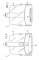
- Figure 5 is a front view of the dispenser shown in Figure 1.
- Figure 6 is a top plan view of the dispenser shown in Figure 1.
- Figure 7 is a side view of the dispenser shown in Figure 1, the other side view being a mirror image.
- Figure 8 is a partial cross-sectional view taken along line 8-8 in Figure 7 showing the means for attaching the extension plate to the wicking device of the dispenser shown in Figure 1.
- Figure 9 is a top plan view of a second embodiment of a dispenser according to the invention having an alternative extension plate.
- Figure 10 is a side view of the dispenser shown in Figure 9, the other side view being a mirror image.
- Figure 11 is a partial cross-sectional view taken along line 11-11 in Figure 10 showing the means for attaching the alternative extension plate to the wicking device of the dispenser shown in Figure 10.
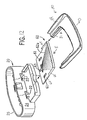
- Figure 12 illustrates schematically the manner in which a wicking device may be inserted into the base of the first embodiment of the dispenser shown in Figure 1 and in which an extension plate may be attached to the wicking device.
- Figure 13 illustrates schematically the manner in which the alternative extension plate may be attached to the base of the second embodiment of the dispenser shown in Figure 9.
- Figure 14 is a side view showing the first embodiment of the dispenser shown in Figure 1 installed on an open rim type toilet bowl.
- Figure 15 is a view similar to Figure 14, but with the first embodiment of the dispenser shown in Figure 1 installed on a box rim type toilet bowl.
- Figure 16 is a side view showing the second embodiment of the dispenser shown in Figure 9 installed on an open rim type toilet bowl.
- Figure 17 is a view similar to Figure 16, but with the second embodiment of the dispenser installed on a box rim type toilet bowl.
- Figure 18 is a perspective view of a wicking device that may be inserted into the base of the dispenser shown in Figure 1 or Figure 9.
- Figure 19 is a perspective view of another version of a wicking device that may be inserted into the base of the dispenser shown in Figure 1 or Figure 9.
- a liquid dispenser 10 for dispensing liquid toilet bowl treatment preparations from the rim of a toilet bowl.
- the dispenser 10 includes a base 20, a sprung suspension hook 40 for suspending the base 20 from the rim of a toilet bowl (as shown in Figures 14 and 15), a reservoir bottle 50 containing a liquid 58, a wicking device 60 that is supported by the base 20, and a removable extension plate 80 that is secured to the wicking device 60.
- the liquid 58 used in the bottle 50 may be any liquid formula having the cleaning, foaming, disinfecting and fragrancing characteristics required for the specific toilet cleaning application.
- One example liquid 58 comprises an anionic surfactant, a nonionic surfactant, a solvent, a sequesterant, a base to control pH, a thickener, a preservative, a fragrance, and a dye.
- Another example liquid is disclosed in European patent application no. EP 775,741 and comprises 1-25 wt.% perfume, 10-50 wt.% anionic or non-ionic surfactant, 1-20 wt.% evaporation regulator, and balance solvent.
- a wicking device 60 which may be in the form of a dispensing plate or a porous pad, is located within the base 20, and this wicking device 60 conveys by capillary action the liquid 58 from the reservoir bottle 50 to a position within the stream of flushing water within the toilet bowl.
- the base 20, the suspension hook 40, the bottle 50, and the extension plate 80 it is preferable to manufacture these components from a thermoplastic material such as polyethylene or polypropylene.
- the base 20, the suspension hook 40 and the extension plate 80 comprise an opaque thermoplastic material such as pigmented polyethylene or polypropylene
- the bottle 50 comprises a transparent thermoplastic material such as clear polyethylene or polypropylene.
- the suspension hook 40 is formed as a separate component from the base 20, and the base 20 is formed with an integral guide channel 21 (see Figure 2) of rectangular cross-section into which the lower end of the suspension hook 40 is inserted during assembly.
- the lower end of the suspension hook 40 comprises a raised, chamfered portion 42, such that, upon insertion, the hook 40 remains engaged within the channel 21 by a snap-fitting arrangement.
- the base 20 includes a side wall 24 that terminates at an upper edge 25.
- the side wall 24 and the upper edge 25 create a mounting structure that holds the bottle 50 when the bottle 50 is installed on the base 20.
- the inner surface of the side wall 24 may also include ribs to further retain the bottle 50 in the base 20.
- annular channel 27 that runs adjacent a piercing post 30 that is used to carry fluids from the bottle 50 when the liquid dispensing device 10 is installed on a toilet rim.
- the base 20 is also formed with a series of drain slots 28 (best shown in Figure 5) at the bottom of the front side which allow the flushing water to drain away from above the wicking device 60.
- the installation of the bottle 50 on the base 20 is best shown in Figures 2 and 3.
- the piercing post 30 of the base 20 comprises a cylindrical tubular section 32 that defines a feed conduit 34.
- An upper end 33 of the tubular section 32 terminates obliquely to form an elliptical mouth.
- the bottle 50 includes a circular mouth 52 that is covered by a closure 54 that seals the liquid 58 in the bottle 50 for shipment and storage.
- the closure 54 is a thermoplastic cap with a channel that engages a circular flange at the mouth 52 of the bottle 50.
- Other closures, such as foil or plastic film, would also be suitable for sealing the mouth 52 of the bottle 50.
- the central portion of the closure 54 shown in Figure 3 has a frangible seal with a circular area of reduced thickness.
- the inverted bottle 50 is oriented over the piercing post 30 of the base 20 such that the circular inner wall of the closure 54 approximately lines up with the circular outer surface of the piercing post 30, and the bottle is moved in a downward direction until the upper end 33 of the piercing post 30 causes the circular area of the frangible seal to fracture.
- the feed conduit 34 of the base 20 is then placed in fluid communication with the mouth 52 of the bottle 50 and liquid 58 may flow from the bottle 50 through the feed conduit 34 and out of a dispensing hole 36 at the bottom of the piercing post 30 by way of gravity.
- the base 20 further comprises an outlet portion 38 in the form of a cylinder which bears against the wicking device 60.
- the manner in which the wicking device 60 is installed in the base 20 and the manner in which the extension plate 80 is secured to the wicking device 60 are illustrated in Figures 8 and 12.
- the wicking device 60 is provided with two elongate guide slots 61 which are engaged by two corresponding spring fingers 22 in the base 20.
- the wicking device 60 in moved in the direction of arrow I in Figure 12 until the guide slots 61 are engaged by the spring fingers 22.
- the guide slots 61 serve to define the two extreme positions of the range of possible positions of the wicking device 60 within the base 20.
- the extension plate 80 is provided with a channel 81 in an inner wall 82 of the extension plate 80.
- the extension plate 80 is moved in the direction of arrow E in Figure 12 until an edge 65 of the wicking device 60 is inserted in the channel 81 in the inner wall 82 of the extension plate 80.
- An interference fit between the edge 65 of the wicking device 60 and the channel 81 in the inner wall 82 of the extension plate 80 serves to keep the extension plate 80 secured to the wicking device 60.
- the extension plate 80 may be removed from the wicking device 60 by pulling the extension plate 80 in direction O in Figure 12.
- the inner wall 82 of the extension plate 80 includes projections 86 (best shown in Figure 8) that provide a snap fit engagement between the wicking device 60 and the extension plate 80.
- additional projections may be provided on the extension plate 80 such that a snap fit engagement between the extension plate 80 and the base 20 occurs.
- the extension plate 80 may also include an upwardly extending rim 84 at a perimeter thereof.
- the wicking device 60 may be a dispensing plate including capillary feed channels 62a that are arranged in radiating fashion in the top surface of a non-porous plate 64.
- the wicking device 60 may be also be a dispensing plate including capillary feed channels 62b that are arranged in parallel fashion in the top surface of the non-porous plate 64.
- a recess 63 is formed within the wicking device 60 to accommodate fluid from the inverted reservoir bottle 50.
- the wicking device 60 is attached to the base 20 such that the recess 63 of the wicking device 60 is placed in fluid communication with the feed conduit 34 of the base 20.
- the outlet portion 38 at the bottom of the piercing post 30 is used to provide a fluid path between feed conduit 34 and the recess 63 of the wicking device 60.
- liquid flows out of the bottle 58, into the feed conduit 34 of the base 20, through the outlet portion 38 and into the recess 63 of the wicking device 60.
- Liquid 58 then flows from the recess 63 of the wicking device 60 into the capillary feed channels 62a or 62b in the upper surface of the wicking device 60. The liquid then continues to move toward the outer end of the capillary feed channels 62a or 62b where the liquid is mixed with flush water.
- Various means can be used to move the liquid from the recess 63 of the wicking device 60 into the capillary feed channels 62a or 62b.
- the capillary action provided by adherence of the fluid to the sides of the capillary feed channels 62a or 62b serves to move the liquid toward the outer end of the capillary channels 62a or 62b.
- Figure 14 illustrates the configuration of the dispensing device 10 when used with a toilet 140 with an open rim. With the dispensing device 10 suspended from the rim 160 of such a toilet 140, it can be seen that the stream of flushing water, indicated by the arrow W, contacts the extension plate 80. When used with a toilet 14b of the boxed-rim configuration, as shown in Figure 15, the stream of flushing water, indicated by the arrow W, also contacts the extension plate 80.
- the extension plate 80 is dimensioned such that the extension plate 80 is positioned within the flow of water during a toilet flush.
- the operation of the dispenser 10 can be explained further.
- the dispenser 10 is ready for operation.
- the liquid 58 flows out of the bottle 50, into the feed conduit 34 of the base 20, through the outlet portion 38 and onto the wicking device 60.
- Liquid 58 then flows toward the outer end of the wicking device 60 by way of capillary action of the capillary channels 62a or 62b as described above.
- the flow of flush water contacts the extension plate 80, and the flush water is directed onto the outer end of the wicking device 60.
- the liquid 58 on the wicking device 60 is mixed with flush water, and a mixture including flush water and liquid 58 is then distributed into the toilet. After the flushing water washes liquid 58 from the wicking device 60 into the toilet water, a fresh supply of liquid 58 is distributed from the bottle to the wicking device 60 as described above. The fresh supply of liquid 58 is then available for the next toilet flush.
- the dispenser 10a includes a base 20 (as described above), a sprung suspension hook 40 (as described above) for suspending the base 20 from the rim of a toilet bowl (as shown in Figures 16 and 17), a reservoir bottle 50 (as described above) containing a liquid 58 (as described above), a wicking device 60 (as described above) that is supported by the base 20, and a removable extension plate 80a that is secured to a support structure 39 that is integral with the base 20.
- the bottle 50 is installed on the base 20 of the dispenser 10a as described above for the first embodiment of the dispenser 10.
- the manner in which the extension plate 80a is secured to the support structure 39 of the base 20 is illustrated in Figure 13.
- the extension plate 80a is provided with a channel 81 a in an inner wall 82a of the extension plate 80a.
- the extension plate 80a is moved in the direction of arrows X in Figure 13 until an edge 39a of the support structure 39 of the base 20 is inserted in the channel 81 a in the inner wall 82a of the extension plate 80a.
- An interference fit between the edge 39a of the support structure 39 of the base 20 and the channel 81 a in the inner wall 82a of the extension plate 80a serves to keep the extension plate 80a secured to the edge 39a of the support structure 39 of the base 20.
- the extension plate 80a may be removed from the edge 39a of the support structure 39 of the base 20 by pulling the extension plate 80a in direction Y in Figure 13.
- the inner wall 82a of the extension plate 80a includes projections that provide a snap fit engagement between the edge 39a of the support structure 39 of the base 20 and the extension plate 80a.
- the extension plate 80a may also include an upwardly extending rim 84a at a perimeter thereof.
- Figure 16 illustrates the configuration of the dispensing device 10a when used with a toilet 140 with an open rim.
- the dispensing device 10a suspended from the rim 160 of such a toilet 140, it can be seen that the stream of flushing water, indicated by the arrow W, contacts the extension plate 80a.
- the stream of flushing water indicated by the arrow W
- the extension plate 80a is dimensioned such that the extension plate 80a is positioned within the flow of water during a toilet flush.
- the operation of the dispenser 10a can be explained further.
- the dispenser 10a is ready for operation.
- the liquid 58 flows out of the bottle 50, into the feed conduit 34 of the base 20, through the outlet portion 38 and onto the wicking device 60.
- Liquid 58 then flows toward the outer end of the wicking device 60 by way of capillary action of the capillary channels 62a or 62b as described above.
- the flow of flush water contacts the extension plate 80a, and the flush water is directed onto the outer end of the wicking device 60.
- the liquid 58 on the wicking device 60 is mixed with flush water, and a mixture including flush water and liquid 58 is then distributed into the toilet. After the flushing water washes liquid 58 from the wicking device 60 into the toilet water, a fresh supply of liquid 58 is distributed from the bottle to the wicking device 60 as described above. The fresh supply of liquid 58 is available for the next toilet flush.
- the wicking device is in the form of a dispensing plate 70 having the same overall shape as the wicking device 60 that is illustrated in Figures 1-18, with elongate guide slots 72 that provide adjustability of position of the plate 70.
- the plate 70 is solid apart from a number of raised through-holes 73 formed in the plate.
- liquid 58 flows out of the bottle 58, into the feed conduit 34 of the base 20, through the outlet portion 38 and onto the plate 70.
- the liquid 58 is mixed with flush water as described above.
- a mixture including flush water and liquid is then distributed into the toilet through through-holes 73 in the plate 70.
- the through-holes 73 are sufficiently small to prevent the undiluted liquid 58 from passing through.
- a second alternative structure of the wicking device is a porous pad that is used to provide a fluid path between the bottle 50 and a dispensing position within the stream of flush water.
- the porous pad has the same overall shape as the wicking device 60 that is illustrated in Figures 1-18, with elongate guide slots that provide adjustability of position of the pad.
- liquid 58 flows out of the bottle 58, into the feed conduit 34 of the base 20, through the outlet portion 38 and onto the porous pad. The liquid then continues to move toward the outer end of the porous pad by capillary action where the liquid is mixed with flush water as described above.
- the dispenser 10 and the dispenser 10a have many advantages.
- One advantage can be understood by looking at Figure 15 which shows dispenser 10 installed on a toilet rim 16b. It can be seen that the stream of flushing water, indicated by the arrow W, will contact the extension plate 80 of the dispenser 10 during a toilet flush because the extension plate 80 is dimensioned such that the extension plate 80 is positioned within the flow of water during a toilet flush, and in this example, is positioned in contact with an inner wall 17 of the toilet bowl 14b.
- the extension plate 80 then directs the flush water onto the outer end of the wicking device 60.
- the liquid 58 on the wicking device 60 is mixed with flush water, and a mixture including flush water and liquid 58 is then distributed into the toilet.
- the extension plates 80 and 80a may include an upwardly extending rim at a perimeter thereof to further optimize the flush water collection and distribution functions of the extension plates 80 and 80a.
- FIG 14 shows dispenser 10 installed on a toilet rim 160.
- the extension plate 80 is dimensioned and secured to the wicking device 60 such that the wicking device 60 is inclined downwardly with respect to an inner wall 15 of the toilet bowl 140 when the dispenser 10 is installed on the rim 160 of the toilet bowl 140.
- One way the inclination of the wicking device 60 can be achieved is by configuring the extension plate 80 such that the extension plate 80 is fixed against rotational movement with respect to the wicking device 60 when the extension plate 80 is secured to the wicking device 60.
- the channel 81 in the extension plate 80 described above is one such configuration.
- the extension plate 80 is fixedly positioned in the same plane as the wicking device 60 and is removable from the wicking device 60 by movement in the same plane as the wicking device 60.
- the downward inclination of the wicking device 60 serves to improve the fluid delivery performance of the dispenser 10 when installed on a toilet rim.
- Figure 16 shows that the wicking device 60 is inclined downwardly with respect to the inner wall 15 of the toilet bowl 140 when the dispenser 10a is installed on the rim 160 of the toilet bowl 140.
- the downward inclination of the wicking device 60 serves to improve the fluid delivery performance of the dispenser 10a when installed on a toilet rim.
- the extension plate 80 can be installed on the dispenser 10 to provide a downward inclination to the wicking device 60, if desired.
- the installation of the extension plate 80a on the dispenser 10a provides identical results.
- the dispensing device includes an extension plate that may be added to the device such that the toilet flush water may be collected and directed over a dispensing plate regardless of the toilet configuration thereby effectively washing the cleaning and freshening liquids off the dispensing plate and into the toilet bowl.
- the extension plate may be added to the device such that the dispensing plate is inclined downwardly toward the inner wall of the toilet bowl when installed on the toilet rim thereby optimizing the fluid delivery performance of the device.
- the under the toilet rim liquid cleansing and/or freshening device includes an extension plate that may be added to the device such that the device may work effectively in the vast majority of toilets marketed worldwide.
- the invention may be used for dispensing liquids, such as cleaning and freshening liquids, from under the rim of a toilet bowl by way of the flow of water during a toilet flush.
- liquids such as cleaning and freshening liquids
Landscapes
- Health & Medical Sciences (AREA)
- Public Health (AREA)
- Epidemiology (AREA)
- Life Sciences & Earth Sciences (AREA)
- Engineering & Computer Science (AREA)
- Hydrology & Water Resources (AREA)
- Water Supply & Treatment (AREA)
- Bidet-Like Cleaning Device And Other Flush Toilet Accessories (AREA)
- Cleaning In General (AREA)
Claims (11)
- Dispositif de distribution (10) destiné à utiliser un écoulement d'eau pendant un tirage de chasse d'eau pour distribuer des préparations liquides de traitement de cuvette de toilettes dans une cuvette de toilettes, le dispositif comprenant :un flacon (50) destiné à contenir un liquide, le flacon (50) comportant une ouverture (52) et une fermeture (54) destinée à recouvrir l'ouverture (52) ;une base (20) destinée à contenir le flacon (50), la base (20) comportant un montant de percée (30), le montant de percée (30) étant approprié pour ouvrir la fermeture (54) du flacon (50) ;un moyen de suspension (40) destiné à suspendre la base (20) à un rebord de la cuvette de toilettes ;un dispositif à effet de mèche (60) supporté par la base (20), le dispositif à effet de mèche (60) étant approprié pour acheminer le liquide du montant de percée (30) jusqu'à une position de distribution sur le dispositif à effet de mèche (60) ; etune plaque d'extension (80), la plaque d'extension (80) étant dimensionnée de sorte que la plaque d'extension (80) soit positionnée dans l'écoulement d'eau pendant un tirage de chasse d'eau et de sorte qu'au moins une partie de l'écoulement d'eau soit dirigée sur la position de distribution du dispositif à effet de mèche (60) pendant un tirage de chasse d'eau, caractérisé en ce que la plaque d'extension (80) est fixée de manière amovible au dispositif à effet de mèche (60), et dans lequel la plaque d'extension (80) est dimensionnée et fixée au dispositif à effet de mèche (60) de sorte que le dispositif à effet de mèche soit incliné vers le bas par rapport à une paroi intérieure de la cuvette de toilettes lorsque le dispositif de distribution (10) est installé sur le rebord de la cuvette de toilettes ; et dans lequel la plaque d'extension (80) est fixe à l'encontre d'un déplacement rotatif par rapport au dispositif à effet de mèche (60) lorsqu'elle est fixée au dispositif à effet de mèche (60).
- Dispositif de distribution selon la revendication 1, dans lequel la plaque d'extension est fixée au dispositif à effet de mèche par un engagement par emboîtement.
- Dispositif de distribution selon la revendication 1, dans lequel la plaque d'extension est fixée au dispositif à effet de mèche en insérant un bord du dispositif à effet de mèche dans un canal dans une paroi intérieure de la plaque d'extension.
- Dispositif de distribution (10) destiné à utiliser un écoulement d'eau pendant un tirage de chasse d'eau pour distribuer des préparations liquides de traitement de cuvette de toilettes dans une cuvette de toilettes, le dispositif comprenant :un flacon (50) destiné à contenir un liquide, le flacon comportant une ouverture (52) et une fermeture (54) destinée à recouvrir l'ouverture ;une base (20) destinée à contenir le flacon, la base comportant un montant de percée (30), le montant de percée étant approprié pour ouvrir la fermeture du flacon ;un moyen de suspension (40) destiné à suspendre la base à un rebord de la cuvette de toilettes ;un dispositif à effet de mèche (60) supporté par la base, le dispositif à effet de mèche étant approprié pour acheminer le liquide du montant de percée jusqu'à une position de distribution sur le dispositif à effet de mèche ; etune plaque d'extension (80a), la plaque d'extension (80a) étant dimensionnée de sorte que la plaque d'extension (80a) soit positionnée dans l'écoulement d'eau pendant un tirage de chasse d'eau et de sorte qu'au moins une partie de l'écoulement d'eau soit dirigée sur la position de distribution du dispositif à effet de mèche (60) pendant un tirage de chasse d'eau, caractérisé en ce que la plaque d'extension (80a) est fixée de manière amovible à la base (20), et dans lequel la plaque d'extension (80a) est dimensionnée et fixée à la base (20) de sorte que le dispositif à effet de mèche (60) soit incliné vers le bas par rapport à une paroi intérieure de la cuvette de toilettes lorsque le dispositif de distribution (10) est installé sur le rebord de la cuvette de toilettes ; et dans lequel la plaque d'extension (80a) est fixe à l'encontre d'un déplacement rotatif par rapport à la base (20) lorsqu'elle est fixée à la base (20).
- Dispositif de distribution selon la revendication 4, dans lequel la plaque d'extension est fixée à la base par un engagement par emboîtement.
- Dispositif de distribution selon la revendication 4, dans lequel la plaque d'extension est fixée à la base en insérant un bord de la base dans un canal dans une paroi intérieure de la plaque d'extension.
- Dispositif de distribution selon la revendication 1 ou 4, dans lequel la plaque d'extension comprend un rebord s'étendant vers le haut au niveau d'un périmètre de celle-ci.
- Dispositif de distribution selon la revendication 1 ou 4, dans lequel la plaque d'extension est positionnée de manière fixe dans le même plan que le dispositif à effet de mèche.
- Dispositif de distribution selon la revendication 1 ou 4, dans lequel le dispositif à effet de mèche comprend une plaque de distribution comportant une surface supérieure comprenant au moins un canal d'alimentation en communication fluidique avec le montant de percée de la base.
- Dispositif de distribution selon la revendication 1 ou 4, dans lequel le dispositif à effet de mèche comprend une plaque avec des trous formés dedans.
- Dispositif de distribution selon la revendication 1 ou 4, dans lequel le dispositif à effet de mèche comprend une pastille poreuse.
Applications Claiming Priority (3)
| Application Number | Priority Date | Filing Date | Title |
|---|---|---|---|
| US198999 | 2002-07-19 | ||
| US10/198,999 US6651261B1 (en) | 2002-07-19 | 2002-07-19 | Toilet rim mounted toilet cleaner with extension plate |
| PCT/US2003/022185 WO2004009919A1 (fr) | 2002-07-19 | 2003-07-16 | Bloc desinfectant fixe sur le rebord d'une toilette avec plaque d'extension |
Publications (2)
| Publication Number | Publication Date |
|---|---|
| EP1415054A1 EP1415054A1 (fr) | 2004-05-06 |
| EP1415054B1 true EP1415054B1 (fr) | 2007-02-21 |
Family
ID=29584044
Family Applications (1)
| Application Number | Title | Priority Date | Filing Date |
|---|---|---|---|
| EP03765605A Expired - Lifetime EP1415054B1 (fr) | 2002-07-19 | 2003-07-16 | Bloc desinfectant fixe sur le rebord d'une toilette avec plaque d'extension |
Country Status (10)
| Country | Link |
|---|---|
| US (1) | US6651261B1 (fr) |
| EP (1) | EP1415054B1 (fr) |
| JP (2) | JP2005533947A (fr) |
| AT (1) | ATE354702T1 (fr) |
| AU (1) | AU2003259133B2 (fr) |
| CA (1) | CA2493060C (fr) |
| DE (1) | DE60311937T2 (fr) |
| MX (1) | MXPA05000820A (fr) |
| NZ (1) | NZ537924A (fr) |
| WO (1) | WO2004009919A1 (fr) |
Families Citing this family (48)
| Publication number | Priority date | Publication date | Assignee | Title |
|---|---|---|---|---|
| DE10164866B4 (de) * | 2000-11-17 | 2007-06-14 | Henkel Kgaa | Abgabevorrichtung zur Abgabe von Wirkstofffluiden in die Spülflüssigkeit in einem Toilettenbecken |
| NL1019393C2 (nl) * | 2001-11-19 | 2003-05-20 | Sara Lee De Nv | Inrichting met een toiletverzorgende werking. |
| DE10204928B4 (de) * | 2002-02-07 | 2004-04-01 | Henkel Kgaa | Abgabevorrichtung zur Abgabe eines Wirkstofffluids in die Spülflüssigkeit in einem Toilettenbecken |
| DE20215129U1 (de) * | 2002-10-01 | 2003-03-13 | Skot S A Chemical Products Att | Vorrichtung zur Abgabe eines flüssigen Wirkstoffs |
| US6898806B2 (en) * | 2002-10-01 | 2005-05-31 | Skot S.A. Chemical Products | Device for dispensing a liquid active substance |
| USD507326S1 (en) * | 2002-10-02 | 2005-07-12 | Skot S.A. Chemical Products | Distributor plate for use with a device for dispensing a liquid active substance |
| USD508107S1 (en) * | 2004-04-08 | 2005-08-02 | Ljc Technologies, Llc | Primary fluid distribution plate |
| USD506807S1 (en) * | 2004-04-08 | 2005-06-28 | Ljc Technologies, Llc | Secondary fluid distribution plate |
| ITRE20040084A1 (it) * | 2004-07-14 | 2004-10-14 | Re Le Vi Spa | Dispenser per wc con camera profumante |
| DE202004013910U1 (de) * | 2004-09-03 | 2006-01-12 | Henkel Kgaa | Befestigungsklammer für eine Abgabevorrichtung |
| USD520103S1 (en) * | 2004-11-03 | 2006-05-02 | Ljc Technologies, Llc | Tertiary fluid distribution plate |
| USD541370S1 (en) * | 2004-12-09 | 2007-04-24 | Ljc Technologies, Llc | Transition plate |
| US20060130221A1 (en) * | 2004-12-20 | 2006-06-22 | Bulala Cherie A | Multi-function toilet device |
| GB2426981B (en) * | 2005-06-09 | 2008-09-17 | Brian Parry Slade | Dispensing device |
| US7603726B2 (en) | 2005-12-20 | 2009-10-20 | S.C. Johnson & Son, Inc. | Toilet bowl cleaning and/or deodorizing device |
| US8291524B2 (en) * | 2005-12-20 | 2012-10-23 | S.C, Johnson & Son, Inc. | Clip for mounting a fluid delivery device |
| US20070240252A1 (en) * | 2005-12-20 | 2007-10-18 | Leonard Stephen B | Clip for mounting a fluid delivery device |
| EP1891197B1 (fr) | 2006-03-22 | 2008-08-27 | Reckitt Benckiser Inc. | Procédé de fabrication de dispenseurs améliorés |
| EP2952570B1 (fr) * | 2006-06-23 | 2021-07-28 | Reckitt Benckiser LLC | Améliorations apportées à des dispositifs de distribution et compositions s'y rapportant |
| USD583903S1 (en) | 2007-07-31 | 2008-12-30 | S.C. Johnson & Son, Inc. | Bottle holder |
| USD581010S1 (en) | 2007-07-31 | 2008-11-18 | S.C. Johnson & Son, Inc. | Bottle holder |
| USD591824S1 (en) | 2007-07-31 | 2009-05-05 | S.C. Johnson & Son, Inc. | Dispenser mounting device |
| US8307467B2 (en) | 2007-08-23 | 2012-11-13 | The Clorox Company | Toilet device with indicator |
| GB0718420D0 (en) * | 2007-09-21 | 2007-10-31 | Reckitt Benckiser Inc | Improvements in dispensing devices |
| JP5665279B2 (ja) * | 2008-03-31 | 2015-02-04 | 小林製薬株式会社 | 薬液供給装置 |
| JP5121536B2 (ja) * | 2008-03-31 | 2013-01-16 | 小林製薬株式会社 | 薬液供給装置 |
| GB2461549A (en) * | 2008-07-03 | 2010-01-06 | Reckitt Benckiser Inc | Process for preparing a cageless device for dispensing a lavatory treatment composition |
| GB0812141D0 (en) * | 2008-07-03 | 2008-08-06 | Reckitt Benckiser Inc | Improvements in dispensing devices |
| DE102008037723A1 (de) * | 2008-08-14 | 2010-02-25 | Henkel Ag & Co. Kgaa | WC-Körbchen mit Spülwasserverteilelement |
| USD649235S1 (en) | 2010-11-09 | 2011-11-22 | S.C. Johnson & Son, Inc. | Container holder |
| USD667944S1 (en) | 2010-11-09 | 2012-09-25 | S.C. Johnson & Son, Inc. | Dispenser mounting device |
| US8549675B2 (en) | 2010-11-26 | 2013-10-08 | S.C. Johnson & Son, Inc. | Toilet bowl cleaning device including dual activation mechanism |
| WO2015036636A1 (fr) * | 2013-09-10 | 2015-03-19 | Zobele España, S.A. | Dispositif pour la distribution d'un produit à l'intérieur de la cuvette des toilettes |
| WO2016040341A1 (fr) | 2014-09-08 | 2016-03-17 | S. C. Johnson & Son, Inc. | Bloc de rebord de toilettes et son procédé de fabrication |
| USD752198S1 (en) | 2015-03-18 | 2016-03-22 | S.C. Johnson & Son, Inc. | Toilet rim block holder |
| USD752733S1 (en) | 2015-03-18 | 2016-03-29 | S.C. Johnson & Son, Inc. | Toilet rim block holder |
| KR101815319B1 (ko) * | 2016-03-29 | 2018-01-04 | 한국디비케이 주식회사 | 방향제가 구비된 변기 세정장치 |
| USD784491S1 (en) | 2016-05-17 | 2017-04-18 | S. C. Johnson & Son, Inc. | Toilet rim block |
| USD789485S1 (en) | 2016-05-17 | 2017-06-13 | S. C. Johnson & Son, Inc. | Toilet rim block holder |
| US10669705B2 (en) | 2016-07-05 | 2020-06-02 | Willert Home Products, Inc. | Toilet bowl treatment apparatus and method of making same |
| USD841120S1 (en) | 2017-01-31 | 2019-02-19 | S. C. Johnson & Son, Inc. | Toilet rim-block |
| USD850578S1 (en) | 2017-01-31 | 2019-06-04 | S. C. Johnson & Son, Inc. | Toilet rimblock |
| AU2018280622A1 (en) * | 2017-06-04 | 2020-01-16 | Killer Whale L.T.D | Toilet cleaning devices systems and methods |
| USD912761S1 (en) | 2019-06-07 | 2021-03-09 | S. C. Johnson & Son, Inc. | Toilet rim-block |
| USD923139S1 (en) | 2019-06-07 | 2021-06-22 | S. C. Johnson & Son, Inc. | Set of toilet rim-blocks |
| USD914131S1 (en) | 2019-06-07 | 2021-03-23 | S. C. Johnson & Son, Inc. | Toilet rim-block holder |
| JP7402732B2 (ja) * | 2020-03-31 | 2023-12-21 | 小林製薬株式会社 | 薬液供給装置 |
| JP2026503855A (ja) * | 2023-02-05 | 2026-01-30 | トイボット リミテッド | 便器を清掃するためのデバイス |
Family Cites Families (38)
| Publication number | Priority date | Publication date | Assignee | Title |
|---|---|---|---|---|
| US1067472A (en) | 1912-10-14 | 1913-07-15 | Fred A Creed | Disinfectant-holder. |
| US1091265A (en) | 1913-04-23 | 1914-03-24 | Benjamin Armer | Sanitary attachment for toilet-bowls and the like. |
| US1880912A (en) | 1931-05-29 | 1932-10-04 | Mary E Forchheimer | Deodorant container for toilet bowls |
| US3537112A (en) | 1967-08-18 | 1970-11-03 | Richard E Goodman | Toilet deodorant |
| US3529309A (en) | 1968-08-12 | 1970-09-22 | Madison Chem Corp | Lavatory sanitation bodies |
| US3604021A (en) | 1969-05-15 | 1971-09-14 | Elton Ind Corp | Urinal tablet |
| US3675254A (en) | 1970-08-31 | 1972-07-11 | Hysan Products Co | Treatment device |
| US3766576A (en) | 1971-07-14 | 1973-10-23 | Chemtrust Ind Corp | Lavatory sanitation bodies |
| US3736600A (en) | 1971-12-20 | 1973-06-05 | J Drinkwater | Toilet-bowl disinfectant-detergent holder and dispenser |
| IT1030072B (it) | 1973-11-02 | 1979-03-30 | Tamin El Sioufy | Dispositivo per la disinfezione e pulitura chimica del vaso di gabinetti |
| US4096593A (en) | 1976-07-15 | 1978-06-27 | Eftichios Van Vlahakis | Toilet bowl dispenser |
| USRE32017E (en) | 1978-04-24 | 1985-11-05 | Globol-Werk Gmbh | Toilet flush water colorizer |
| DE7834350U1 (de) | 1978-11-18 | 1979-03-22 | Globol-Werk Gmbh, 8858 Neuburg | Halterung fuer wc-desodorantien |
| DE2917083B1 (de) | 1979-04-27 | 1980-07-10 | Globol Werke Gmbh | Halterung fuer WC-Desodorantien |
| FR2532346B1 (fr) | 1982-08-26 | 1985-05-10 | Reckitt & Colmann Sa | Support perfectionne pour produits nettoyants et/ou colorants, destine a etre accroche sous le rebord d'une cuvette de wc |
| DE3639686A1 (de) | 1986-11-20 | 1988-05-26 | Henkel Kgaa | Wc-koerbchen |
| US4777670A (en) | 1988-01-13 | 1988-10-18 | S. C. Johnson & Son, Inc. | Under-the-rim dispensing unit |
| WO1990010122A1 (fr) | 1989-02-28 | 1990-09-07 | Ingrid Liesk | Distributeur automatique de quantites definies de substances actives dans des cuvettes de toilettes, commande par la chasse d'eau |
| IT1232105B (it) | 1989-05-25 | 1992-01-23 | Del Santo Luigi | Attrezzo igienico per la pulizia e il mantenimento della stessa in vasi di w.c |
| NL9101759A (nl) | 1991-10-22 | 1993-05-17 | Sara Lee De Nv | Vloeibaar-reinigings- en/of verfrissingsmiddel voor een toiletpot. |
| NL1001722C2 (nl) | 1995-11-22 | 1997-05-23 | Sara Lee De Nv | Reinigings- en verfrissingseenheid bestemd om te worden opgehangen aan een toiletpotrand. |
| DE19720393A1 (de) * | 1997-05-15 | 1998-11-19 | Buck Chemie Gmbh | Reinigungs- und Erfrischungsvorrichtung für Toilettenbecken |
| GB2370290B (en) | 1998-06-15 | 2002-10-23 | Johnson & Son Inc S C | Method of filling and sealing a dispenser bottle for use as a reservoir within a liquid dispensing unit |
| GB2338495B (en) | 1998-06-15 | 2000-08-09 | Johnson & Son Inc S C | A unit for dispensing a liquid from the rim of a lavatory bowl |
| DE19855304A1 (de) | 1998-12-01 | 2000-06-15 | Buck Chemie Gmbh | Vorrichtung zur Abgabe von Zusatzstoffen an das Spülwasser in WC-Becken |
| DE19912217C2 (de) | 1999-01-12 | 2002-09-05 | Jeyes Deutschland Gmbh | Vorrichtung zur Abgabe von Wirkstoffen in das Spülwasser insbesondere in Toilettenbecken |
| DE29902066U1 (de) | 1999-02-08 | 1999-04-22 | Georg Menshen GmbH & Co KG, 57413 Finnentrop | Vorrichtung zur Konditionierung von Spülflüssigkeit bei sanitären Einrichtungen |
| DE19915322C1 (de) | 1999-04-03 | 2001-01-18 | Henkel Kgaa | Nachfüllbares WC-Körbchen für Flüssigreiniger |
| CN1271047A (zh) | 1999-04-19 | 2000-10-25 | 莎拉李/迪有限公司 | 悬垂于抽水马桶边缘的净化和清新设备 |
| GB9915601D0 (en) | 1999-07-02 | 1999-09-01 | Globol Chem Uk Ltd | A dispenser |
| AU4649099A (en) | 1999-07-14 | 2001-01-30 | Deoflor S.P.A. | Device for delivering an active substance in liquid phase inside a toilet bowl |
| DE29912647U1 (de) | 1999-07-26 | 1999-09-23 | Weiß, Oliver, 90530 Wendelstein | Spender für Toiletten-Hygiene-Flüssigkeiten |
| IT1310977B1 (it) | 1999-10-28 | 2002-02-27 | Relevi S P A | Dispenser per sostanze attive per vaso di wc. |
| EP1226313B1 (fr) | 1999-11-02 | 2008-06-04 | Jeyes Group Limited | Dispositifs de distribution de liquide |
| US6178564B1 (en) | 1999-12-14 | 2001-01-30 | S. C. Johnson & Son, Inc. | Liquid dispensing toilet rim mounted toilet bowl cleaner |
| IT1311606B1 (it) | 1999-12-14 | 2002-03-13 | Falp Srl | Erogatore regolabile di tensioattivi e/o di liquidiigienizzanti/deodoranti. |
| FR2809123B1 (fr) | 2000-05-19 | 2003-01-10 | Eurvest S A | Distributeur de liquide d'entretien pour toilettes |
| FR2813331B1 (fr) | 2000-08-22 | 2003-04-04 | Brill Manitoba Spa | Dispositif de nettoyage et de rafraichissement d'une cuvette de w.c. |
-
2002
- 2002-07-19 US US10/198,999 patent/US6651261B1/en not_active Expired - Lifetime
-
2003
- 2003-07-16 CA CA002493060A patent/CA2493060C/fr not_active Expired - Fee Related
- 2003-07-16 WO PCT/US2003/022185 patent/WO2004009919A1/fr not_active Ceased
- 2003-07-16 EP EP03765605A patent/EP1415054B1/fr not_active Expired - Lifetime
- 2003-07-16 DE DE60311937T patent/DE60311937T2/de not_active Expired - Lifetime
- 2003-07-16 NZ NZ537924A patent/NZ537924A/en unknown
- 2003-07-16 MX MXPA05000820A patent/MXPA05000820A/es active IP Right Grant
- 2003-07-16 JP JP2004523448A patent/JP2005533947A/ja not_active Ceased
- 2003-07-16 AT AT03765605T patent/ATE354702T1/de not_active IP Right Cessation
- 2003-07-16 AU AU2003259133A patent/AU2003259133B2/en not_active Expired
-
2009
- 2009-06-03 JP JP2009133775A patent/JP2009191607A/ja active Pending
Also Published As
| Publication number | Publication date |
|---|---|
| CA2493060C (fr) | 2007-10-16 |
| DE60311937D1 (de) | 2007-04-05 |
| WO2004009919A1 (fr) | 2004-01-29 |
| AU2003259133A1 (en) | 2004-02-09 |
| AU2003259133B2 (en) | 2008-05-01 |
| CA2493060A1 (fr) | 2004-01-29 |
| MXPA05000820A (es) | 2005-04-19 |
| ATE354702T1 (de) | 2007-03-15 |
| EP1415054A1 (fr) | 2004-05-06 |
| DE60311937T2 (de) | 2007-10-31 |
| JP2009191607A (ja) | 2009-08-27 |
| US6651261B1 (en) | 2003-11-25 |
| JP2005533947A (ja) | 2005-11-10 |
| NZ537924A (en) | 2006-04-28 |
Similar Documents
| Publication | Publication Date | Title |
|---|---|---|
| EP1415054B1 (fr) | Bloc desinfectant fixe sur le rebord d'une toilette avec plaque d'extension | |
| US7114199B2 (en) | Toilet rim mounted device for dispensing two liquids | |
| US6662380B1 (en) | Dual action toilet rim mounted toilet bowl cleaner | |
| US6178564B1 (en) | Liquid dispensing toilet rim mounted toilet bowl cleaner | |
| KR100657426B1 (ko) | 액체 분배용 변기 림에 장착된 변기 세정기 | |
| JP4423184B2 (ja) | 液体を便器に放出するための分配装置 | |
| US6625821B2 (en) | Dispenser for adding a cleaning and/or deodorizing product to a toilet bowl |
Legal Events
| Date | Code | Title | Description |
|---|---|---|---|
| PUAI | Public reference made under article 153(3) epc to a published international application that has entered the european phase |
Free format text: ORIGINAL CODE: 0009012 |
|
| 17P | Request for examination filed |
Effective date: 20040226 |
|
| AK | Designated contracting states |
Kind code of ref document: A1 Designated state(s): AT BE BG CH CY CZ DE DK EE ES FI FR GB GR HU IE IT LI LU MC NL PT RO SE SI SK TR |
|
| AX | Request for extension of the european patent |
Extension state: AL LT LV MK |
|
| 17Q | First examination report despatched |
Effective date: 20040830 |
|
| DAX | Request for extension of the european patent (deleted) | ||
| GRAP | Despatch of communication of intention to grant a patent |
Free format text: ORIGINAL CODE: EPIDOSNIGR1 |
|
| GRAS | Grant fee paid |
Free format text: ORIGINAL CODE: EPIDOSNIGR3 |
|
| GRAA | (expected) grant |
Free format text: ORIGINAL CODE: 0009210 |
|
| AK | Designated contracting states |
Kind code of ref document: B1 Designated state(s): AT BE BG CH CY CZ DE DK EE ES FI FR GB GR HU IE IT LI LU MC NL PT RO SE SI SK TR |
|
| PG25 | Lapsed in a contracting state [announced via postgrant information from national office to epo] |
Ref country code: NL Free format text: LAPSE BECAUSE OF FAILURE TO SUBMIT A TRANSLATION OF THE DESCRIPTION OR TO PAY THE FEE WITHIN THE PRESCRIBED TIME-LIMIT Effective date: 20070221 Ref country code: DK Free format text: LAPSE BECAUSE OF FAILURE TO SUBMIT A TRANSLATION OF THE DESCRIPTION OR TO PAY THE FEE WITHIN THE PRESCRIBED TIME-LIMIT Effective date: 20070221 Ref country code: SI Free format text: LAPSE BECAUSE OF FAILURE TO SUBMIT A TRANSLATION OF THE DESCRIPTION OR TO PAY THE FEE WITHIN THE PRESCRIBED TIME-LIMIT Effective date: 20070221 Ref country code: CH Free format text: LAPSE BECAUSE OF FAILURE TO SUBMIT A TRANSLATION OF THE DESCRIPTION OR TO PAY THE FEE WITHIN THE PRESCRIBED TIME-LIMIT Effective date: 20070221 Ref country code: LI Free format text: LAPSE BECAUSE OF FAILURE TO SUBMIT A TRANSLATION OF THE DESCRIPTION OR TO PAY THE FEE WITHIN THE PRESCRIBED TIME-LIMIT Effective date: 20070221 Ref country code: AT Free format text: LAPSE BECAUSE OF FAILURE TO SUBMIT A TRANSLATION OF THE DESCRIPTION OR TO PAY THE FEE WITHIN THE PRESCRIBED TIME-LIMIT Effective date: 20070221 Ref country code: FI Free format text: LAPSE BECAUSE OF FAILURE TO SUBMIT A TRANSLATION OF THE DESCRIPTION OR TO PAY THE FEE WITHIN THE PRESCRIBED TIME-LIMIT Effective date: 20070221 Ref country code: BE Free format text: LAPSE BECAUSE OF FAILURE TO SUBMIT A TRANSLATION OF THE DESCRIPTION OR TO PAY THE FEE WITHIN THE PRESCRIBED TIME-LIMIT Effective date: 20070221 |
|
| REG | Reference to a national code |
Ref country code: GB Ref legal event code: FG4D |
|
| REG | Reference to a national code |
Ref country code: CH Ref legal event code: EP |
|
| REF | Corresponds to: |
Ref document number: 60311937 Country of ref document: DE Date of ref document: 20070405 Kind code of ref document: P |
|
| REG | Reference to a national code |
Ref country code: IE Ref legal event code: FG4D |
|
| PG25 | Lapsed in a contracting state [announced via postgrant information from national office to epo] |
Ref country code: SE Free format text: LAPSE BECAUSE OF FAILURE TO SUBMIT A TRANSLATION OF THE DESCRIPTION OR TO PAY THE FEE WITHIN THE PRESCRIBED TIME-LIMIT Effective date: 20070521 |
|
| PG25 | Lapsed in a contracting state [announced via postgrant information from national office to epo] |
Ref country code: BG Free format text: LAPSE BECAUSE OF EXPIRATION OF PROTECTION Effective date: 20070522 |
|
| PG25 | Lapsed in a contracting state [announced via postgrant information from national office to epo] |
Ref country code: ES Free format text: LAPSE BECAUSE OF FAILURE TO SUBMIT A TRANSLATION OF THE DESCRIPTION OR TO PAY THE FEE WITHIN THE PRESCRIBED TIME-LIMIT Effective date: 20070601 |
|
| PG25 | Lapsed in a contracting state [announced via postgrant information from national office to epo] |
Ref country code: PT Free format text: LAPSE BECAUSE OF FAILURE TO SUBMIT A TRANSLATION OF THE DESCRIPTION OR TO PAY THE FEE WITHIN THE PRESCRIBED TIME-LIMIT Effective date: 20070723 |
|
| NLV1 | Nl: lapsed or annulled due to failure to fulfill the requirements of art. 29p and 29m of the patents act | ||
| ET | Fr: translation filed | ||
| REG | Reference to a national code |
Ref country code: CH Ref legal event code: PL |
|
| PG25 | Lapsed in a contracting state [announced via postgrant information from national office to epo] |
Ref country code: SK Free format text: LAPSE BECAUSE OF FAILURE TO SUBMIT A TRANSLATION OF THE DESCRIPTION OR TO PAY THE FEE WITHIN THE PRESCRIBED TIME-LIMIT Effective date: 20070221 |
|
| PLBE | No opposition filed within time limit |
Free format text: ORIGINAL CODE: 0009261 |
|
| STAA | Information on the status of an ep patent application or granted ep patent |
Free format text: STATUS: NO OPPOSITION FILED WITHIN TIME LIMIT |
|
| PG25 | Lapsed in a contracting state [announced via postgrant information from national office to epo] |
Ref country code: CZ Free format text: LAPSE BECAUSE OF FAILURE TO SUBMIT A TRANSLATION OF THE DESCRIPTION OR TO PAY THE FEE WITHIN THE PRESCRIBED TIME-LIMIT Effective date: 20070221 Ref country code: RO Free format text: LAPSE BECAUSE OF FAILURE TO SUBMIT A TRANSLATION OF THE DESCRIPTION OR TO PAY THE FEE WITHIN THE PRESCRIBED TIME-LIMIT Effective date: 20070221 |
|
| 26N | No opposition filed |
Effective date: 20071122 |
|
| PG25 | Lapsed in a contracting state [announced via postgrant information from national office to epo] |
Ref country code: GR Free format text: LAPSE BECAUSE OF FAILURE TO SUBMIT A TRANSLATION OF THE DESCRIPTION OR TO PAY THE FEE WITHIN THE PRESCRIBED TIME-LIMIT Effective date: 20070522 Ref country code: MC Free format text: LAPSE BECAUSE OF NON-PAYMENT OF DUE FEES Effective date: 20070731 Ref country code: IT Free format text: LAPSE BECAUSE OF FAILURE TO SUBMIT A TRANSLATION OF THE DESCRIPTION OR TO PAY THE FEE WITHIN THE PRESCRIBED TIME-LIMIT Effective date: 20070221 |
|
| PG25 | Lapsed in a contracting state [announced via postgrant information from national office to epo] |
Ref country code: IE Free format text: LAPSE BECAUSE OF NON-PAYMENT OF DUE FEES Effective date: 20070716 |
|
| PG25 | Lapsed in a contracting state [announced via postgrant information from national office to epo] |
Ref country code: EE Free format text: LAPSE BECAUSE OF FAILURE TO SUBMIT A TRANSLATION OF THE DESCRIPTION OR TO PAY THE FEE WITHIN THE PRESCRIBED TIME-LIMIT Effective date: 20070221 |
|
| PG25 | Lapsed in a contracting state [announced via postgrant information from national office to epo] |
Ref country code: CY Free format text: LAPSE BECAUSE OF FAILURE TO SUBMIT A TRANSLATION OF THE DESCRIPTION OR TO PAY THE FEE WITHIN THE PRESCRIBED TIME-LIMIT Effective date: 20070221 |
|
| PG25 | Lapsed in a contracting state [announced via postgrant information from national office to epo] |
Ref country code: LU Free format text: LAPSE BECAUSE OF NON-PAYMENT OF DUE FEES Effective date: 20070716 |
|
| PG25 | Lapsed in a contracting state [announced via postgrant information from national office to epo] |
Ref country code: TR Free format text: LAPSE BECAUSE OF FAILURE TO SUBMIT A TRANSLATION OF THE DESCRIPTION OR TO PAY THE FEE WITHIN THE PRESCRIBED TIME-LIMIT Effective date: 20070221 Ref country code: HU Free format text: LAPSE BECAUSE OF FAILURE TO SUBMIT A TRANSLATION OF THE DESCRIPTION OR TO PAY THE FEE WITHIN THE PRESCRIBED TIME-LIMIT Effective date: 20070822 |
|
| REG | Reference to a national code |
Ref country code: FR Ref legal event code: PLFP Year of fee payment: 14 |
|
| REG | Reference to a national code |
Ref country code: FR Ref legal event code: PLFP Year of fee payment: 15 |
|
| REG | Reference to a national code |
Ref country code: FR Ref legal event code: PLFP Year of fee payment: 16 |
|
| PGFP | Annual fee paid to national office [announced via postgrant information from national office to epo] |
Ref country code: GB Payment date: 20220621 Year of fee payment: 20 |
|
| PGFP | Annual fee paid to national office [announced via postgrant information from national office to epo] |
Ref country code: FR Payment date: 20220622 Year of fee payment: 20 |
|
| PGFP | Annual fee paid to national office [announced via postgrant information from national office to epo] |
Ref country code: DE Payment date: 20220621 Year of fee payment: 20 |
|
| P01 | Opt-out of the competence of the unified patent court (upc) registered |
Effective date: 20230528 |
|
| REG | Reference to a national code |
Ref country code: DE Ref legal event code: R071 Ref document number: 60311937 Country of ref document: DE |
|
| REG | Reference to a national code |
Ref country code: GB Ref legal event code: PE20 Expiry date: 20230715 |
|
| PG25 | Lapsed in a contracting state [announced via postgrant information from national office to epo] |
Ref country code: GB Free format text: LAPSE BECAUSE OF EXPIRATION OF PROTECTION Effective date: 20230715 |