EP1415587A2 - Lave-vaisselle - Google Patents
Lave-vaisselle Download PDFInfo
- Publication number
- EP1415587A2 EP1415587A2 EP03256562A EP03256562A EP1415587A2 EP 1415587 A2 EP1415587 A2 EP 1415587A2 EP 03256562 A EP03256562 A EP 03256562A EP 03256562 A EP03256562 A EP 03256562A EP 1415587 A2 EP1415587 A2 EP 1415587A2
- Authority
- EP
- European Patent Office
- Prior art keywords
- water
- air
- washing chamber
- washing
- temperature
- Prior art date
- Legal status (The legal status is an assumption and is not a legal conclusion. Google has not performed a legal analysis and makes no representation as to the accuracy of the status listed.)
- Withdrawn
Links
Images




Classifications
-
- A—HUMAN NECESSITIES
- A47—FURNITURE; DOMESTIC ARTICLES OR APPLIANCES; COFFEE MILLS; SPICE MILLS; SUCTION CLEANERS IN GENERAL
- A47L—DOMESTIC WASHING OR CLEANING; SUCTION CLEANERS IN GENERAL
- A47L15/00—Washing or rinsing machines for crockery or tableware
- A47L15/42—Details
- A47L15/4285—Water-heater arrangements
-
- A—HUMAN NECESSITIES
- A47—FURNITURE; DOMESTIC ARTICLES OR APPLIANCES; COFFEE MILLS; SPICE MILLS; SUCTION CLEANERS IN GENERAL
- A47L—DOMESTIC WASHING OR CLEANING; SUCTION CLEANERS IN GENERAL
- A47L15/00—Washing or rinsing machines for crockery or tableware
- A47L15/42—Details
- A47L15/48—Drying arrangements
Definitions
- the present invention relates to a method of heating water for washing items in a dishwasher comprising a chamber to receive said items to be washed.
- a dishwasher is an apparatus that removes contaminants from dishes by spraying cool water or hot water on the dishes disposed on racks in a washing chamber. To remove contaminants, pumps and nozzles are used to spray washing water and rinsing water, and a heater is required to generate the hot water.
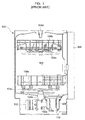
- a conventional dishwasher is described below with reference to Figure 1 of the accompanying drawings.
- Figure 1 is a vertical sectional view of a conventional dishwasher 100 having a washing chamber 104 with an opening in a front thereof and a door 106 connected to the front of a body 102 of the dishwasher with hinges to open or close the opening.
- Dish racks 104a are slidably mounted in upper and lower portions of the washing chamber 104 to hold the dishes that are to be cleaned.
- Upper and lower spray nozzles 104c that spray the washing water on the dishes are disposed under the dish racks 104a, respectively.
- a heater 150 is disposed under the lower dish rack 104a to heat the washing and rinsing water.
- hot water is generated by a heat exchange between the supplied water and the heater 150.
- the hot water is used to remove food dregs on the dishes, or to soak dried food dregs and remove them in a washing process.
- the hot water is also used to heat the dishes for a rinsing process. If the dishes are heated using the hot water in a last operation of the rinsing process, the dishes then dry more quickly in a subsequent drying process because the water is rapidly vaporised by the latent heat of the dishes.
- a water tank 108 is disposed in a space under the dish rack 104a in the lower portion of the washing chamber 104 to contain washing or rinsing water, and is connected to a discharge pump 110 and a water supply pump 112 through a discharge pipe 110a and a circulation pipe 112a, respectively.
- the circulation pipe 112a is connected to water supply pipes 104b connected to the upper and lower spray nozzles 104c, respectively.
- washing or rinsing water which is circulated inside the washing chamber 104, is sprayed from the upper and lower spray nozzles 104c, passes into and through the water tank 108 and the circulation pipe 112a, is supplied to the water supply pipes 104b, and is then resprayed from the upper and lower spray nozzles 104c, thereby being recirculated inside the washing chamber 104 by the water supply pump 112.
- the washing or rinsing water is discharged from the body 102 of the dishwasher 100 by the discharge pump 110.
- the heater 150 In the water heating operation of a conventional dishwasher 100, the heater 150 is submerged under the water which results in compounds of calcium (e.g. calcites) forming on the surface thereof, thereby shortening its lifetime. Furthermore, since the water is directly heated, it takes a relatively long period of time to generate hot water. Another problem arises when the heater 150 is used to heat the air in the washing chamber 104 to perform a drying process, as the dishes become excessively heated, and so they are too hot to be removed immediately after the drying process is complete.
- compounds of calcium e.g. calcites
- One type of conventional dishwasher exists in which an exterior heater is installed in a separate space outside the washing chamber and is constructed to supply water heated by the heater to the washing chamber.
- the heater is again submerged under the water so there remains the problems that the lifetime of the heater is shortened by being covered with the calcium compounds, the required washing time is increased because of the direct heating of the water, and considerable energy is consumed in the process.
- a conventional dishwasher having an exterior heater rinses the dishes using hot water during the last operation of the rinsing process instead of heating air in the washing chamber. This prevents the dishes from being excessively heated in the drying process, and they then rapidly dry due to their latent heat.
- an independent drying process in which the water is not required cannot be performed. This is also not energy efficient as heating the water requires a lot of electrical power.
- a method of heating water for washing items in a dishwasher comprising a chamber to receive said items to be washed and an air heater remote from the chamber, the method including the step of supplying water for washing to the chamber, characterised by the steps of heating air using the air heater and supplying said heated air to the chamber to heat the water in the chamber.
- the method includes the steps of supplying hot air and water to the washing chamber until a first condition is reached, thereafter stopping the water supply and only continuing to generate and supply hot air to the washing chamber.
- the method also preferably includes the steps of continuing to generate and supply hot air after the first condition is reached until a second condition is reached, thereafter restarting water supply to the washing chamber.
- the first condition is a first predetermined temperature of water in the washing chamber.
- the first condition is the elapse of a first predetermined period of time.
- the second condition is a second predetermined temperature of the air in the washing chamber.
- the second condition may also be the elapse of a second predetermined period of time.
- the method preferably includes commencing supplying the water and the hot air simultaneously, or may alternatively include supplying hot air for a predetermined period of time before commencing supplying water.
- the method may also include supplying hot air until air inside the washing chamber and reaches a predetermined temperature and then commencing the supply of water.
- a preferred method includes initially supplying water to the washing chamber intermittently until the first condition is reached.
- the present invention also provides a dishwasher having a washing chamber to receive items to be washed in washing water characterised by means to generate and supply hot air to the washing chamber including an air heater remote from the chamber, operable to heat air to heat washing water supplied to the chamber.
- FIG. 2A shows a dishwasher 200 comprising a washing chamber 204 having an opening in a front thereof, provided in a body 202, and a door 206 connected to the front of the body 202 with hinges to open or close the opening in the washing chamber 204.
- Upper and lower dish racks 204a are slidably mounted in upper and lower portions of the washing chamber 204 respectively, to hold dishes to be cleaned.
- Upper and lower spray nozzles 204c are disposed under the upper and lower dish racks 204a respectively to spray washing water on the dishes.
- a water tank 208 is disposed under the washing chamber 204 to contain the washing water or rinsing water, and is connected to a discharge pump 210 and a water supply pump 212 through a discharge pipe 210a and a circulation pipe 212a, respectively.
- the circulation pipe 212a is connected to water supply pipes 204b, which are connected to the upper and lower spray nozzles 204c.
- the washing or rinsing water is sprayed from the spray nozzles 204c, is collected in and passes through the water tank 208 and passes through the circulation pipe 212a, is supplied to the water supply pipes 204b, and then is resprayed out of the upper and lower spray nozzles 204c, and is thereby continually recirculated inside the washing chamber 204 by the water supply pump 212.
- the washing or rinsing water is discharged from the body 202 of the dishwasher 200 by the discharge pump 210.
- a heater 250 and a blowing fan 254 are disposed in the door 206 to heat and circulate air in the washing chamber 204 respectively.
- An air inlet 252a and an air outlet 252c are disposed in a surface of the door 206 facing and communicating with the washing chamber 204, and communicate with each other through an airflow conduit 252b.
- the blowing fan 254, rotated by a fan motor 254a, is disposed in the conduit 252b beside the air inlet 252a and the heater 250 is disposed in the middle of the conduit 252b.
- the air in the washing chamber 204 is drawn into the conduit 252b through air inlet 252a, is heated by the heater 250 and then expelled into the washing chamber 204 through the outlet 252c, thereby being circulated within the washing chamber 204.
- the position of the heater 250 and the blowing fan 254 are not limited to inside of the door 206 within the scope of the invention and may be disposed in other positions of the body 202 of the dishwasher 200. Further, the dishwasher 200 may be provided with an independent casing outside of the body 202, so that the heater 250 and the blowing fan 254 may be disposed in the casing.
- the air inlet may be configured such that it communicates with both the inside of the washing chamber 204 and the outside of the body 202 of the dishwasher 200, so that the air can be drawn from both inside the washing chamber 204 and outside of the dishwasher 200 and then supplied to the washing chamber 204.
- the air inlet may only be disposed on the outside of the dishwasher 200 so that only air from outside the dishwasher 200 is drawn in and heated, and then supplied to the washing chamber 204.
- FIG. 2B is a block diagram showing the functional construction of the dishwasher 200 according to the first embodiment of the present invention.
- a control unit 260 which controls the overall operation of the dishwasher 200, is connected at input terminals thereof to a key input unit 262 and a temperature sense unit 264.
- the key input unit 262 is used to receive operating conditions of the dishwasher 200 from a user and set the operating conditions.
- the temperature sensing unit 264 is used to measure the temperature of the air in the washing chamber 204.
- the control unit 260 is connected at output terminals thereof to a water supply/discharge valve drive unit 266, a water supply pump drive unit 268, a heater drive unit 270 and a fan drive unit 272.
- the water supply/discharge valve drive unit 266 is used to drive a water supply valve 274 and a water discharge valve 276.
- the water supply/circulation pump drive unit 268 and the heater drive unit 270 are used to drive the water supply pump 212 and the hater 250 respectively.
- the fan drive unit 272 drives the fan motor 254a to operate the blowing fan 254.
- the dishwasher 200 is provided with various operating conditions by selectively turning on/off the blowing fan 254, the heater 250 and the water supply pump 212.
- the operating conditions shown in Table 1 are as follows:
- FIG. 3 is a graph of temperature and water supply control characteristics of the dishwasher 200, according to the first embodiment of the present invention.
- the air in the washing chamber 204 is continuously circulated and the heater 250 is simultaneously operated until the temperature of the air in the washing chamber 204 reaches a preset target temperature.
- the air in the washing chamber 204 is heated, the dishes are heated and oil and other contaminants on the dishes are melted and generally loosened from the surface of the dishes so that the subsequent washing process is more effective and so the necessary washing period is decreased.
- washing water is periodically supplied into the washing chamber 204 to be heated by the hot air.
- the control unit 260 may alternatively set a time point at which to supply the washing water to control the temperature of the air in the washing chamber 204, or it may be controlled relative to the length of time the heater 250 and the blowing fan 254 have been on. That is, the washing water may be supplied when the temperature of the air in the washing chamber 204 reaches a preset reference temperature or after the hater 250 and the blowing fan 254 have been on for a preset reference time. Furthermore, the washing water may be supplied at the same time that the heater 250 and the blowing fan 254 are on.
- washing water By heating the air in the washing chamber 204, the temperature therein is sufficiently raised within a short period of time because air has a specific heat lower than that of water. Washing water is then supplied to the washing chamber 204 and is heated by the hot air and so the time required for the washing water to be heated is shorter than in conventional dishwashers which directly heat the washing water. Furthermore, if the washing water is supplied after the dishes have been heated to remove contaminants, such as oil as described above, the subsequent necessary washing time is shortened and the washing efficiency is further increased. The washing water may also be supplied whilst the air in the washing chamber 204 is being heated to prevent food dregs on the dishes from being dried and hardened by the hot air.
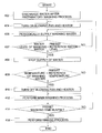
- FIG. 4 is a flowchart of a washing process of the dishwasher 200, according to the first embodiment of the present invention, wherein an initial preparatory washing process is performed, to remove large-sized contaminants from the dishes, and the used washing water is then discharged at operation 402. Thereafter, in operation 404, the blowing fan 254 and the heater 250 are turned on, so that the air in the washing chamber 204 is heated. When the temperature of the air in the washing chamber 204 increases by a certain amount, the washing water is periodically supplied to the washing chamber 204 in operation 406 where it is heated by the hot air. If the temperature of the air in the washing chamber 204 is 80 ⁇ 90°C, the temperature of the washing water increases to 40 ⁇ 50°C.
- Operation 407 determines whether the water level of the washing water has reached a preset reference water level and if so, the supply of the washing water is stopped at operation 408. Although the supply of the washing water is stopped, the blowing fan 254 and the heater 250 are still on, so the air in the washing chamber 204 is heated, and the washing water is heated by the hot air.
- a query at operation 409 determines whether the temperature of the washing water has reached a preset reference temperature, and if so, the blowing fan 254 and the heater 250 are turned off at operation 410, and the main washing process is performed in operation 412 by circulation of the washing water.
- Query operation 414 determines whether a preset washing time has elapsed and if so, the main washing process is stopped and a rinsing process is performed at operation 416.
- FIG. 5 is a flowchart of the rinsing process of the dishwasher, according to the first embodiment of the present invention.
- the blowing fan 254 and the heater 250 are turned on, and the air in the washing chamber 204 is heated.
- rinsing water is supplied at operation 504 and is heated by the hot air.
- hot water is not necessarily required to rinse the dishes, heated rinsing water has a desirable disinfecting effect.
- a subsequent drying process is speeded up by using hot water in the rinsing operation because of the resulting higher latent heat of the dishes.
- Operation 505 determines whether the water level of the rinsing water has reached a preset reference water level and if so, the supply of the rinsing water is stopped at operation 506 and the last operation of the rinsing process is performed at operation 507.
- Operation 508 determines whether a rinsing time has reached a preset rinsing time and if so, the blowing fan 254 and the heater 250 are turned off at operation 510, the used rinsing water is discharged at operation 512 and the drying process is performed at operation 514.
- a conventional dishwasher 100 uses hot water to rinse the dishes and relies on the latent heat of the hot dishes in the drying process.
- the dishwasher 200 of the present invention blows hot air into the washing chamber 204 during the drying process so does not need to heat the dishes by rinsing with hot water in the earlier rinsing process.
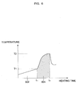
- Figure 6 is a graph showing temperature and water supply control characteristics of the dishwasher 200 and illustrates a curve showing a variation of temperature in the washing chamber 204.
- a first period 602 i.e. from time 0 to t1 is the temperature of water in the washing chamber 204
- a second period 604 i.e. from time t1 to t2 illustrates the temperature of the air in the washing chamber 204.
- the temperature of the water is required to reach a first target temperature T1
- the blowing fan 254 the heater 250 and the water supply pump 212 are all operating so the air in the washing chamber 204 is heated and the water is simultaneously supplied so the temperature of the water slowly increases.
- the water supply pump 212 When the temperature of the water reaches the first target temperature T1, the water supply pump 212 is turned off. Since the supply of the water is stopped, heating of the air is accelerated, and it therefore reaches a second target temperature T2 in a short period of time. In the second period 604 from t1 to t2, only the blowing fan 254 and the heater 250 operate. If the temperature of the air in the washing chamber 204 reaches the second target temperature T2, the water supply pump 212 restarts and the water receives heat from the air, so the temperature of the air in the washing chamber 204 rapidly decreases.
- the second period 604 applies to a case where a very high temperature is needed, for example, the removal of lipstick residue from the surface of a cup because lipstick has a melting point of more than 80°C.
- a very high temperature for example, the removal of lipstick residue from the surface of a cup because lipstick has a melting point of more than 80°C.
- To make the cup reach such a temperature using washing water would require a relatively long time to heat the water and a lot of energy.
- the specific heat of the air is much lower than that of water and so the air in the washing chamber 204 can be heated to an equally high temperature much more quickly and using much less energy.
- Figures 7 and 8 are flowcharts showing methods of controlling the dishwasher 200 to heat the water and air as per the graph shown in Figure 6, according to second and third embodiments of the present invention respectively.
- the method of Figure 7 is dependent on the variation of the temperature of air in the washing chamber 204.
- operation 702 water is supplied to the washing chamber 204 as the washing or rinsing process is started.
- the water supply pump 212, the heater 250 and the blowing fan 254 all operate in operation 704 to heat air in and water supplied to the washing chamber 204.
- Operation 706 determines whether the temperature of the water in the washing chamber 204 exceeds a first reference temperature T r1 , and if so, the water supply pump 212 is switched off in operation 708 and only the blowing fan 254 and the heater 250 continue to operate.
- Operation 710 determines whether the temperature of the air in the washing chamber 204 exceeds a second reference temperature T r2 and if so, the water supply pump 212 is restarted in operation 712 to supply water to the washing chamber 204, and the washing of dishes is carried out. Since the dishes have been heated by the hot air at this point, stains or debris such as lipstick or oil that have a high melting point are more easily removed. After a preset time has elapsed for the washing or rinsing process, the process ends at operation 714.
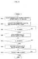
- the method of controlling the dishwasher shown in the flowchart of Figure 8 is based on a preset time period for each process.
- operation 802 water is supplied to the washing chamber 204 as the washing or rinsing process is started.
- the water supply pump 212, the heater 250 and blowing fan 254 are all on in operation 804 to heat the air, and water supplied to the washing chamber 204.
- Operation 806 determines whether a first reference time t r1 , has elapsed since the start of the washing or rinsing process and if so, the water supply pump 212 is stopped to stop the supply of the water at operation 808 and only the blowing fan 254 and the heater 250 continue to operate.
- Operation 810 determines whether a second reference time t r2 has elapsed since the start of the washing or rinsing process and if so, the water supply pump 212 is restarted in operation 812 to supply water to the washing chamber 204, and the washing of dishes is performed. After a preset time has elapsed for the washing or rinsing process, the process ends at operation 814.
- the process of the control method shown in Figure 7 is performed based on the variation of temperature whereas the process of the control method shown in Figure 8 is performed based on the elapsed time.
- the first and second reference times t r1 and t r2 are values obtained by taking a mean of times required to reach each of the first and second reference temperatures T r1 and T r2 respectively, found through many tests of the dishwasher 200 at a product development stage.
- the washing water is heated by the hot air so the time required for the washing water to reach the required temperature is shorter than in conventional dishwashers that directly heat the washing water. Furthermore, the supply of the washing water after the removal of contaminants such as oil or lipstick by heating the dishes in the washing chamber 204 as described above, means that the required washing time is shorter and so the washing process is much more efficient than conventional dishwashers.
- the washing water may be supplied as the air in the washing chamber 204 is heated, to prevent food dregs on the dishes from being dried by the hot air.
- the dishwasher is also more energy efficient as it can perform a drying process without the need to have previously perform a rinsing process using hot water.
- Yet another advantage of the present invention is that since the heater is not submerged under the water, compounds of calcium do not form on the surface of the heater and so its lifetime is much longer than that of heaters in conventional dishwashers.
Landscapes
- Washing And Drying Of Tableware (AREA)
Applications Claiming Priority (4)
| Application Number | Priority Date | Filing Date | Title |
|---|---|---|---|
| KR20020067443 | 2002-11-01 | ||
| KR2002067443 | 2002-11-01 | ||
| KR1020030019728A KR20040040302A (ko) | 2002-11-01 | 2003-03-28 | 식기 세척기의 제어 방법 |
| KR2003019728 | 2003-03-28 |
Publications (2)
| Publication Number | Publication Date |
|---|---|
| EP1415587A2 true EP1415587A2 (fr) | 2004-05-06 |
| EP1415587A3 EP1415587A3 (fr) | 2005-06-29 |
Family
ID=32095502
Family Applications (1)
| Application Number | Title | Priority Date | Filing Date |
|---|---|---|---|
| EP03256562A Withdrawn EP1415587A3 (fr) | 2002-11-01 | 2003-10-17 | Lave-vaisselle |
Country Status (4)
| Country | Link |
|---|---|
| US (1) | US7093604B2 (fr) |
| EP (1) | EP1415587A3 (fr) |
| JP (1) | JP3971364B2 (fr) |
| CN (1) | CN1235539C (fr) |
Cited By (17)
| Publication number | Priority date | Publication date | Assignee | Title |
|---|---|---|---|---|
| WO2010012716A1 (fr) * | 2008-07-28 | 2010-02-04 | BSH Bosch und Siemens Hausgeräte GmbH | Procédé de fonctionnement d'un lave-vaisselle |
| DE102010061342A1 (de) * | 2010-12-03 | 2012-06-06 | Whirlpool Corp. (A Delaware Corp.) | Geschirrspüler mit gemeinsam genutzter Heizeinrichtung |
| US8667974B2 (en) | 2009-12-21 | 2014-03-11 | Whirlpool Corporation | Rotating filter for a dishwashing machine |
| US9289107B2 (en) | 2011-12-13 | 2016-03-22 | Ecolab Usa Inc. | Dishmachine |
| US9649007B2 (en) | 2012-10-23 | 2017-05-16 | Whirlpool Corporation | Rotating filter for a dishwasher and methods of cleaning a rotating filter |
| US9668636B2 (en) | 2010-11-16 | 2017-06-06 | Whirlpool Corporation | Method and apparatus for dishwasher with common heating element for multiple treating chambers |
| US9687135B2 (en) | 2009-12-21 | 2017-06-27 | Whirlpool Corporation | Automatic dishwasher with pump assembly |
| US9700196B2 (en) | 2011-05-16 | 2017-07-11 | Whirlpool Corporation | Dishwasher with filter assembly |
| US9730570B2 (en) | 2012-05-30 | 2017-08-15 | Whirlpool Corporation | Reduced sound with a rotating filter for a dishwasher |
| US9833120B2 (en) | 2012-06-01 | 2017-12-05 | Whirlpool Corporation | Heating air for drying dishes in a dishwasher using an in-line wash liquid heater |
| US9861251B2 (en) | 2011-06-20 | 2018-01-09 | Whirlpool Corporation | Filter with artificial boundary for a dishwashing machine |
| US9918609B2 (en) | 2009-12-21 | 2018-03-20 | Whirlpool Corporation | Rotating drum filter for a dishwashing machine |
| US10058228B2 (en) | 2012-02-27 | 2018-08-28 | Whirlpool Corporation | Soil chopping system for a dishwasher |
| US10058227B2 (en) | 2011-06-20 | 2018-08-28 | Whirlpool Corporation | Filter assembly for a dishwasher |
| US10070769B2 (en) | 2011-06-20 | 2018-09-11 | Whirlpool Corporation | Rotating filter for a dishwashing machine |
| US10076226B2 (en) | 2012-05-30 | 2018-09-18 | Whirlpool Corporation | Rotating filter for a dishwasher |
| US10653291B2 (en) | 2011-06-20 | 2020-05-19 | Whirlpool Corporation | Ultra micron filter for a dishwasher |
Families Citing this family (22)
| Publication number | Priority date | Publication date | Assignee | Title |
|---|---|---|---|---|
| TWI282586B (en) * | 2004-02-24 | 2007-06-11 | Innolux Display Corp | Etching system and de-ion water adding set |
| US7959984B2 (en) * | 2004-12-22 | 2011-06-14 | Lam Research Corporation | Methods and arrangement for the reduction of byproduct deposition in a plasma processing system |
| US20060218680A1 (en) * | 2005-03-28 | 2006-09-28 | Bailey Andrew D Iii | Apparatus for servicing a plasma processing system with a robot |
| EP2181636B1 (fr) * | 2008-10-31 | 2016-08-31 | Electrolux Home Products Corporation N.V. | Procédé de fonctionnement d'un lave-vaisselle |
| US8696824B2 (en) | 2009-02-04 | 2014-04-15 | Electrolux Home Products, Inc. | Dishwasher, a door assembly for the dishwasher, and an associated method for drying dishware |
| US10295256B2 (en) | 2009-02-04 | 2019-05-21 | Electrolux Home Products, Inc. | Dishwasher, a door assembly for the dishwasher, and an associated method for drying dishware |
| US8746261B2 (en) * | 2009-12-21 | 2014-06-10 | Whirlpool Corporation | Rotating drum filter for a dishwashing machine |
| US9119515B2 (en) | 2010-12-03 | 2015-09-01 | Whirlpool Corporation | Dishwasher with unitary wash module |
| US8627832B2 (en) | 2010-12-13 | 2014-01-14 | Whirlpool Corporation | Rotating filter for a dishwashing machine |
| US9113766B2 (en) | 2010-11-16 | 2015-08-25 | Whirlpool Corporation | Method and apparatus for dishwasher with common heating element for multiple treating chambers |
| US9107559B2 (en) | 2011-05-16 | 2015-08-18 | Whirlpool Corporation | Dishwasher with filter assembly |
| US9010344B2 (en) | 2011-06-20 | 2015-04-21 | Whirlpool Corporation | Rotating filter for a dishwashing machine |
| US9451862B2 (en) | 2012-06-01 | 2016-09-27 | Whirlpool Corporation | Dishwasher with unitary wash module |
| US9532700B2 (en) | 2012-06-01 | 2017-01-03 | Whirlpool Corporation | Dishwasher with overflow conduit |
| US20170027409A1 (en) * | 2015-07-31 | 2017-02-02 | Illinois Tool Works Inc. | Warewasher with heat recovery system |
| CN107440654A (zh) * | 2017-08-31 | 2017-12-08 | 佛山市顺德区美的洗涤电器制造有限公司 | 洗碗机的控制方法、洗碗机和计算机可读存储介质 |
| CN109864679B (zh) * | 2017-12-01 | 2020-10-30 | 青岛海尔股份有限公司 | 一种冰箱空调洗碗机一体机 |
| US12318054B2 (en) | 2018-09-20 | 2025-06-03 | Electrolux Appliances Aktiebolag | Dishwasher goods drying system |
| WO2020074176A1 (fr) * | 2018-10-08 | 2020-04-16 | Arcelik Anonim Sirketi | Lave-vaisselle comprenant un chauffage |
| KR102658398B1 (ko) * | 2018-11-28 | 2024-04-18 | 엘지전자 주식회사 | 히트펌프를 구비한 식기세척기 |
| CN110419992B (zh) * | 2019-06-24 | 2024-08-16 | 青岛海尔洗碗机有限公司 | 一种洗碗机的控制方法 |
| KR20220144030A (ko) * | 2021-04-16 | 2022-10-26 | 삼성전자주식회사 | 식기세척기 및 식기세척기의 제어방법 |
Family Cites Families (11)
| Publication number | Priority date | Publication date | Assignee | Title |
|---|---|---|---|---|
| US4326552A (en) * | 1979-01-23 | 1982-04-27 | Ingo Bleckmann | Heater for heating flows of fluid and dishwashing machine provided therewith |
| US4247158A (en) * | 1979-07-02 | 1981-01-27 | The Maytag Company | Dishwasher airflow drying system |
| DE8026931U1 (de) * | 1980-10-08 | 1982-02-04 | Bosch-Siemens Hausgeräte GmbH, 7000 Stuttgart | Einrichtung zum erwaermen von spuelfluessigkeit und luft in einer geschirrspuelmaschine |
| DE3830664A1 (de) * | 1988-09-09 | 1990-03-22 | Bauknecht Hausgeraete | Einrichtung zum trocknen von geschirr in einer haushalt-geschirrspuelmaschine |
| KR930003337B1 (ko) * | 1991-05-27 | 1993-04-26 | 삼성전자 주식회사 | 식기세척기의 건조덕트 |
| JP2904454B2 (ja) * | 1991-12-05 | 1999-06-14 | 株式会社東芝 | 食器洗い乾燥機 |
| JP2875720B2 (ja) * | 1993-09-20 | 1999-03-31 | 株式会社日立製作所 | 食器洗い乾燥機 |
| JPH0898797A (ja) * | 1994-09-30 | 1996-04-16 | Sharp Corp | 食器洗い乾燥機 |
| TW338713B (en) * | 1995-09-06 | 1998-08-21 | Sharp Kk | A dishwasher |
| JPH09289965A (ja) * | 1996-04-26 | 1997-11-11 | Hitachi Ltd | 食器洗い機 |
| JP2002263050A (ja) * | 2001-03-12 | 2002-09-17 | Hoshizaki Electric Co Ltd | 食器洗浄機 |
-
2003
- 2003-10-10 JP JP2003352751A patent/JP3971364B2/ja not_active Expired - Fee Related
- 2003-10-10 CN CNB2003101010290A patent/CN1235539C/zh not_active Expired - Fee Related
- 2003-10-17 EP EP03256562A patent/EP1415587A3/fr not_active Withdrawn
- 2003-10-21 US US10/689,518 patent/US7093604B2/en not_active Expired - Fee Related
Cited By (30)
| Publication number | Priority date | Publication date | Assignee | Title |
|---|---|---|---|---|
| WO2010012716A1 (fr) * | 2008-07-28 | 2010-02-04 | BSH Bosch und Siemens Hausgeräte GmbH | Procédé de fonctionnement d'un lave-vaisselle |
| US9918609B2 (en) | 2009-12-21 | 2018-03-20 | Whirlpool Corporation | Rotating drum filter for a dishwashing machine |
| US8667974B2 (en) | 2009-12-21 | 2014-03-11 | Whirlpool Corporation | Rotating filter for a dishwashing machine |
| US10779703B2 (en) | 2009-12-21 | 2020-09-22 | Whirlpool Corporation | Rotating drum filter for a dishwashing machine |
| US9687135B2 (en) | 2009-12-21 | 2017-06-27 | Whirlpool Corporation | Automatic dishwasher with pump assembly |
| US9668636B2 (en) | 2010-11-16 | 2017-06-06 | Whirlpool Corporation | Method and apparatus for dishwasher with common heating element for multiple treating chambers |
| DE102010061342A1 (de) * | 2010-12-03 | 2012-06-06 | Whirlpool Corp. (A Delaware Corp.) | Geschirrspüler mit gemeinsam genutzter Heizeinrichtung |
| US11882977B2 (en) | 2011-05-16 | 2024-01-30 | Whirlpool Corporation | Dishwasher with filter assembly |
| US9700196B2 (en) | 2011-05-16 | 2017-07-11 | Whirlpool Corporation | Dishwasher with filter assembly |
| US10314457B2 (en) | 2011-06-20 | 2019-06-11 | Whirlpool Corporation | Filter with artificial boundary for a dishwashing machine |
| US9861251B2 (en) | 2011-06-20 | 2018-01-09 | Whirlpool Corporation | Filter with artificial boundary for a dishwashing machine |
| US10813525B2 (en) | 2011-06-20 | 2020-10-27 | Whirlpool Corporation | Ultra micron filter for a dishwasher |
| US10653291B2 (en) | 2011-06-20 | 2020-05-19 | Whirlpool Corporation | Ultra micron filter for a dishwasher |
| US10058227B2 (en) | 2011-06-20 | 2018-08-28 | Whirlpool Corporation | Filter assembly for a dishwasher |
| US10070769B2 (en) | 2011-06-20 | 2018-09-11 | Whirlpool Corporation | Rotating filter for a dishwashing machine |
| US10178939B2 (en) | 2011-06-20 | 2019-01-15 | Whirlpool Corporation | Filter with artificial boundary for a dishwashing machine |
| US10314461B2 (en) | 2011-12-13 | 2019-06-11 | Ecolab Usa Inc. | Dishmachine |
| US9289107B2 (en) | 2011-12-13 | 2016-03-22 | Ecolab Usa Inc. | Dishmachine |
| US11191419B2 (en) | 2011-12-13 | 2021-12-07 | Ecolab Usa Inc. | Dishmachine |
| US10349803B2 (en) | 2011-12-13 | 2019-07-16 | Ecolab Usa Inc. | Dishmachine |
| US10058228B2 (en) | 2012-02-27 | 2018-08-28 | Whirlpool Corporation | Soil chopping system for a dishwasher |
| US9730570B2 (en) | 2012-05-30 | 2017-08-15 | Whirlpool Corporation | Reduced sound with a rotating filter for a dishwasher |
| US10076226B2 (en) | 2012-05-30 | 2018-09-18 | Whirlpool Corporation | Rotating filter for a dishwasher |
| US10376128B2 (en) | 2012-05-30 | 2019-08-13 | Whirlpool Corporation | Reduced sound with a rotating filter for a dishwasher |
| US11134825B2 (en) | 2012-05-30 | 2021-10-05 | Whirlpool Corporation | Reduced sound with a rotating filter for a dishwasher |
| US9833120B2 (en) | 2012-06-01 | 2017-12-05 | Whirlpool Corporation | Heating air for drying dishes in a dishwasher using an in-line wash liquid heater |
| US9826882B2 (en) | 2012-10-23 | 2017-11-28 | Whirlpool Corporation | Rotating filter for a dishwasher and methods of cleaning a rotating filter |
| US9649007B2 (en) | 2012-10-23 | 2017-05-16 | Whirlpool Corporation | Rotating filter for a dishwasher and methods of cleaning a rotating filter |
| US9962060B2 (en) | 2012-10-23 | 2018-05-08 | Whirlpool Corporation | Rotating filter for a dishwasher and methods of cleaning a rotating filter |
| US9757008B2 (en) | 2012-10-23 | 2017-09-12 | Whirlpool Corporation | Rotating filter for a dishwasher and methods of cleaning a rotating filter |
Also Published As
| Publication number | Publication date |
|---|---|
| EP1415587A3 (fr) | 2005-06-29 |
| CN1498584A (zh) | 2004-05-26 |
| CN1235539C (zh) | 2006-01-11 |
| JP2004154566A (ja) | 2004-06-03 |
| US7093604B2 (en) | 2006-08-22 |
| JP3971364B2 (ja) | 2007-09-05 |
| US20040134519A1 (en) | 2004-07-15 |
Similar Documents
| Publication | Publication Date | Title |
|---|---|---|
| EP1415587A2 (fr) | Lave-vaisselle | |
| KR101556124B1 (ko) | 식기세척기 및 식기세척기의 제어방법 | |
| KR101481566B1 (ko) | 식기세척기의 제어방법 | |
| KR20100023167A (ko) | 식기세척기의 제어방법 | |
| CN1276742C (zh) | 洗碗机及控制洗碗机的方法 | |
| KR20100023172A (ko) | 식기세척기의 제어방법 | |
| US20080236622A1 (en) | Control method of dish washing machine | |
| KR101396999B1 (ko) | 식기세척기의 제어방법 | |
| US8506721B2 (en) | Dish washer and controlling method thereof | |
| KR100283720B1 (ko) | 식기세정기 및 식기의 세정방법 | |
| KR101306732B1 (ko) | 식기 세척기의 제어방법 | |
| KR101405930B1 (ko) | 식기 세척기의 제어방법 | |
| KR20040040302A (ko) | 식기 세척기의 제어 방법 | |
| JP4591169B2 (ja) | 食器洗い機 | |
| JP7261673B2 (ja) | 加熱調理器 | |
| JP2007229303A (ja) | 食器洗い乾燥機及びその乾燥方法 | |
| JP3985573B2 (ja) | 食器洗い機 | |
| KR0171522B1 (ko) | 식기세척기의 헹굼방법 | |
| KR0171521B1 (ko) | 식기세척기의 식기깨짐방지방법 | |
| JPH0759707A (ja) | 食器洗い機 | |
| JP2007202828A (ja) | 食器洗浄機 | |
| JP2006068400A (ja) | 食器洗い乾燥機 | |
| KR20100023169A (ko) | 식기세척기 및 식기세척기의 제어방법 | |
| JP2006110151A (ja) | 食器洗浄乾燥装置および食器洗浄乾燥制御方法 | |
| JP2007260017A (ja) | 食器洗浄乾燥装置および食器洗浄乾燥方法 |
Legal Events
| Date | Code | Title | Description |
|---|---|---|---|
| PUAI | Public reference made under article 153(3) epc to a published international application that has entered the european phase |
Free format text: ORIGINAL CODE: 0009012 |
|
| AK | Designated contracting states |
Kind code of ref document: A2 Designated state(s): AT BE BG CH CY CZ DE DK EE ES FI FR GB GR HU IE IT LI LU MC NL PT RO SE SI SK TR |
|
| AX | Request for extension of the european patent |
Extension state: AL LT LV MK |
|
| RAP1 | Party data changed (applicant data changed or rights of an application transferred) |
Owner name: SAMSUNG ELECTRONICS CO., LTD. |
|
| RIN1 | Information on inventor provided before grant (corrected) |
Inventor name: SON, WANG-SEOK Inventor name: WOO, JE-HAKC/O SAMSUNG ELECTRONICS CO.,LTD. Inventor name: JANG, SAM-YOUNG Inventor name: HUR, WOON-GU Inventor name: JUNG, TAE-YOUNG |
|
| PUAL | Search report despatched |
Free format text: ORIGINAL CODE: 0009013 |
|
| AK | Designated contracting states |
Kind code of ref document: A3 Designated state(s): AT BE BG CH CY CZ DE DK EE ES FI FR GB GR HU IE IT LI LU MC NL PT RO SE SI SK TR |
|
| AX | Request for extension of the european patent |
Extension state: AL LT LV MK |
|
| 17P | Request for examination filed |
Effective date: 20051111 |
|
| AKX | Designation fees paid |
Designated state(s): DE GB IT |
|
| 17Q | First examination report despatched |
Effective date: 20070531 |
|
| RAP1 | Party data changed (applicant data changed or rights of an application transferred) |
Owner name: SAMSUNG ELECTRONICS CO., LTD. |
|
| STAA | Information on the status of an ep patent application or granted ep patent |
Free format text: STATUS: THE APPLICATION IS DEEMED TO BE WITHDRAWN |
|
| 18D | Application deemed to be withdrawn |
Effective date: 20160503 |