EP1415723A2 - Station de revêtement - Google Patents
Station de revêtement Download PDFInfo
- Publication number
- EP1415723A2 EP1415723A2 EP03103944A EP03103944A EP1415723A2 EP 1415723 A2 EP1415723 A2 EP 1415723A2 EP 03103944 A EP03103944 A EP 03103944A EP 03103944 A EP03103944 A EP 03103944A EP 1415723 A2 EP1415723 A2 EP 1415723A2
- Authority
- EP
- European Patent Office
- Prior art keywords
- coating station
- coating
- web
- station according
- frame
- Prior art date
- Legal status (The legal status is an assumption and is not a legal conclusion. Google has not performed a legal analysis and makes no representation as to the accuracy of the status listed.)
- Granted
Links
Images



Classifications
-
- B—PERFORMING OPERATIONS; TRANSPORTING
- B05—SPRAYING OR ATOMISING IN GENERAL; APPLYING FLUENT MATERIALS TO SURFACES, IN GENERAL
- B05B—SPRAYING APPARATUS; ATOMISING APPARATUS; NOZZLES
- B05B13/00—Machines or plants for applying liquids or other fluent materials to surfaces of objects or other work by spraying, not covered by groups B05B1/00 - B05B11/00
- B05B13/02—Means for supporting work; Arrangement or mounting of spray heads; Adaptation or arrangement of means for feeding work
- B05B13/0207—Means for supporting work; Arrangement or mounting of spray heads; Adaptation or arrangement of means for feeding work the work being an elongated body, e.g. wire or pipe
-
- B—PERFORMING OPERATIONS; TRANSPORTING
- B05—SPRAYING OR ATOMISING IN GENERAL; APPLYING FLUENT MATERIALS TO SURFACES, IN GENERAL
- B05C—APPARATUS FOR APPLYING FLUENT MATERIALS TO SURFACES, IN GENERAL
- B05C5/00—Apparatus in which liquid or other fluent material is projected, poured or allowed to flow on to the surface of the work
- B05C5/02—Apparatus in which liquid or other fluent material is projected, poured or allowed to flow on to the surface of the work the liquid or other fluent material being discharged through an outlet orifice by pressure, e.g. from an outlet device in contact or almost in contact, with the work
- B05C5/0245—Apparatus in which liquid or other fluent material is projected, poured or allowed to flow on to the surface of the work the liquid or other fluent material being discharged through an outlet orifice by pressure, e.g. from an outlet device in contact or almost in contact, with the work for applying liquid or other fluent material to a moving work of indefinite length, e.g. to a moving web
-
- B—PERFORMING OPERATIONS; TRANSPORTING
- B05—SPRAYING OR ATOMISING IN GENERAL; APPLYING FLUENT MATERIALS TO SURFACES, IN GENERAL
- B05C—APPARATUS FOR APPLYING FLUENT MATERIALS TO SURFACES, IN GENERAL
- B05C9/00—Apparatus or plant for applying liquid or other fluent material to surfaces by means not covered by any preceding group, or in which the means of applying the liquid or other fluent material is not important
- B05C9/04—Apparatus or plant for applying liquid or other fluent material to surfaces by means not covered by any preceding group, or in which the means of applying the liquid or other fluent material is not important for applying liquid or other fluent material to opposite sides of the work
Definitions
- This invention relates to a coating station, which is intended for coating the web produced with a forming machine with a selected coating material, comprising a load-bearing and cross-directional frame, which extends substantially across the entire width of the web, as well as applicator elements supported to the frame for applying the coating material to the surface of the web arranged to pass through the coating station.
- non-contacting applicator elements have been developed for the coating stations.
- these developed coating stations use several nozzles for spraying the coating material onto the web surface. This is also referred to as atomizing of coating material.
- Embodiments of this type of coating station are set forth for example in the European patent No. 0826085.
- This patent teaches a method in which coating material, which is most commonly coating paste, is sprayed onto the supported web surface using nozzles connected to a supply pipe.
- the nozzles are additionally adapted in groups, which are located in a specific box for collecting the excess coating material spray.
- the patent also teaches that the coating unit must be provided with a sufficiently rigid frame. However, no more detailed description of the frame is given.
- the frame has heretofore customarily been formed of beam-like construction steels by welding.
- This kind of frame is massive and heavy, the coating station thus becoming large and unwieldy.
- the coating station comprises various pipeworks, which further increase the total weight of the coating station.
- the previously mentioned European patent requires a specific box, which defines a large area. This increases the consumption of the coating material and complicates cleaning in particular when changing the coating material. Cleaning and maintenance of the nozzles located inside the box is also cumbersome.
- the object of the invention is to provide a novel coating station with a simpler and lighter, yet more versatile design compared to the earlier designs, providing more freedom in its positioning in the forming machine.
- the features characterizing this invention become evident from the appended claims.
- the frame is completely of a new kind.
- the frame is unexpectedly formed of special box-type components. This makes the total weight of the frame clearly smaller than is known heretofore. At the same time, the rigidity of the frame is, however, higher than heretofore and the vibration characteristics are better.
- arranged in connection with the box-type components there are for example constructions that have been separate heretofore. Thus the total weight of the coating station can be reduced while the number of components required for the construction decreases. The result is a simple, but rigid coating station frame, which also simplifies the use and maintenance of the coating station.
- Figure 1 shows a principal drawing of the coating station 10 according to the invention. Due to its design and operating principle the coating station is well suitable for a forming machine. The coating station is most commonly used for example in a paper or board machine for coating the produced web with a selected coating material. Coating is used to improve the quality of the final product.
- a coating station includes a load-bearing and cross-directional frame. In the Figures the coating station and its components are shown separated from the rest of the former. In addition, the frame extends substantially across the entire web width. That is, the coating station allows coating of the web in one go throughout the entire width.
- the coating station 10 comprises non-contacting applicator elements 13 for spraying the coating material to the surface of the web 11 arranged to pass through the coating station.
- the applicator elements 13 are supported to the frame 12 and they can be different also as to their operating principles, such as for example blade coaters. The design and operation of the applicator elements is discussed in greater detail later.
- the coating station preferably includes two substantially similar frame structures 12, which contain the applicator elements 13. Consequently, the web 11 can be guided without support between the frame structures 12 set opposed to and at an interval from each other. Thus both of the surfaces of the web 11 are coated simultaneously.
- the use of two opposing frame structures also facilitates the separation of the coating station from the environment, which will be discussed in more detail later.
- the frame of the coating station is arranged by at least one cross component, formed into a box-type structure out of sheet metal, and by end components.
- the cross component extends substantially across the entire web width, the end components being thus positioned outside the web edges.
- the cross component is additionally attached to the end component by its end parts, the end component being supported to the structural frame of the forming machine. Due to the box-type structure the frame and thus the whole coating station become remarkably light and compact. In addition, the rigidity of the box-type structure is good and the deflection caused by its own weight is reduced. Thus the positioning of the actual applicator elements is accurate and they can be positioned sufficiently near to the web.
- the frame comprises three cross components 14, 14' and 14".
- the same reference numbers are used for functionally similar parts.
- the number of cross components varies from one to four.
- This bottom portion of the end component 15 has additionally rollers 16, countering the rails (not shown) that are arranged in the structural frame of the forming machine. This makes it possible to move the coating station off the web for example for maintenance and cleaning.
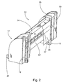
- Figures 2 and 3 also show boxes 17 attached to the end component 15 for housing for example the required electronic components and other auxiliary devices. In Figure 3 one of the boxes is removed. Spacious boxes 17 are formed of a frame 18 attached to the end component 15 and plates 19 attached thereto.
- the plates 19 are placed here only at the ends of the boxes 17, and thereby the openings in the frame 18 are clearly visible.
- the projecting parts 20 in the bottom portions of the end components 15 are additionally used to support a walkway 36, from which the coating station 10 can be monitored and serviced ( Figure 1).
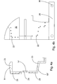
- Figures 4a and 4b show an exploded view of the frame components.
- the end component 15 shown in Figure 4b is also made of sheet metal and it is formed of two substantially similar sheet metal components, adapted at an interval from each other for forming a box-type structure.
- the separate sheet metal components connected by braces 21 appear well also from Figure 3.
- This structure provides an end component that is rigid, yet light in weight. The manufacture and especially maintenance are additionally facilitated by the removability of the cross component.
- the cross component is removably adapted to attach to the end component.
- One or more screw connections or similar are preferably used for the attachment.
- Figure 4b illustrates the holes 22 arranged for the screws.
- Figure 4a illustrates the threaded holes 23 arranged at the ends of the cross components 14, 14' and 14". An accurate hole positioning thus prevents mounting errors.
- the cross components can be replaced even one at a time if required.
- each cross component 14, 14' and 14" is shown in more detail in Figures 5a - 5b.
- the basic design of each cross component hence consists of a box made of sheet metal.
- the rigidity of the cross component is increased by the separation walls 24 arranged inside it at determined intervals.
- the cross component there is also at least one conduit.
- the conduit extends substantially across the entire length of the cross component. In that case separate conduits are not needed.
- the conduit is used especially for recirculating the cooling water in the coating station. Moisture present in a warm environment condenses in the constructions of the coating station due to the cold cooling water.
- the front pan is illustrated with a dot-and-dash line.
- the front pan is substantially straight and covers the cross components.
- the cooling water is used to make the front pan sweat allowing thus a controlled recovery of the excess coating material spray.
- Figure 5b is a sectional view of the cross components 14 and 14' of Figure 1.
- the partition walls 24 additionally have suitable openings 28 for the conduits 25.
- the conduit 25 is formed of profiled sheet metal blade 29, which is unexpectedly attached to that side of the cross component, which is adapted to a straight shape.
- the cross component thus forms a part of the conduit.
- a larger heat exchange surface is obtained compared to a round pipe.
- the wall thickness remains reduced, which further contributes to the heat transfer.
- the sheet metal blade for its part also increases the rigidity of the cross component increasing weight only slightly.
- the number of conduits varies depending mainly on the size of the cross component. Generally the number of conduits varies between one and five. For example, in the lowest cross component of Figure 4a there are five conduits, of which two are located apart from the rest. This allows controlling the temperature of other coating station constructions as well.
- the sheet metal thickness varies from 0.5 to 5 mm, more advantageously from 1 to 3 mm. This helps to obtain easy machining, yet a light and rigid construction in particular when utilizing the box-type structure.
- the cross component, end component and sheet metal blade are laser-cut and laser-welded. Machining works can thus be avoided and the dimensional accuracy of various components is good. Deformations are slight in laser welding and rustproof steel can be used as sheet material. Thus the assembly of the frame and the entire coating station is easy and the finished coating station is durable, yet light in weight.
- sheet metal components also thicker plate can be used, because laser cutting allows industrial cutting of plates with a thickness up to 12 mm. Other functions can also be easily connected to the cross component according to the invention.
- hook-like clamps 30 are formed in the bottom portion of the top-most cross component 14 for a cleaning pipe 31 ( Figure 1).
- fixing points 32 for fixing protective pans for example. Separate brackets are thus unnecessary, which simplifies the manufacture and mounting.
- Figure 1 also shows the applicator elements 13, which here include two nozzle units 33. Each one has nozzles 34 arranged in a row, adapted to extend from inside the frame 12 to the web 11 side of the cross component. Thus the nozzles and their actuators are protected from the coating material spray. In addition, the nozzles open in connection with the front pan. For this purpose, on the front pan there are provided holes 37 for each nozzle ( Figure 1). Consequently, the coating event is well isolated from the environment and the applicator elements.
- Figure 1 also illustrates the use of two substantially similar nozzle units 33 in the coating station. The nozzle units are adapted to operate alternately, for which purpose each nozzle unit has been determined operating and maintenance positions.
- Figure 1 also shows the cleaning device 35, which is pivoted to the end component 15.
- the nozzle unit currently in the maintenance position can also be serviced from the walkway, even if the coating station is in use.
- the coating station according to the invention is suitable for various positions and for coating different types of webs.
- the coating station is versatile and easy to use and service.
- the frame of the coating station is rigid, yet light in weight.
- the coating station is durable and compact in design including fewer components than heretofore.
- the coating event is also well isolated from the environment and the recovery of excess coating material is efficient reducing the loss of coating material.
Landscapes
- Coating Apparatus (AREA)
- Paper (AREA)
- Application Of Or Painting With Fluid Materials (AREA)
- Spray Control Apparatus (AREA)
- Manufacturing And Processing Devices For Dough (AREA)
- Fertilizers (AREA)
- Formation And Processing Of Food Products (AREA)
- Body Structure For Vehicles (AREA)
Applications Claiming Priority (2)
| Application Number | Priority Date | Filing Date | Title |
|---|---|---|---|
| FI20021923 | 2002-10-29 | ||
| FI20021923A FI113290B (fi) | 2002-10-29 | 2002-10-29 | Päällystysasema |
Publications (3)
| Publication Number | Publication Date |
|---|---|
| EP1415723A2 true EP1415723A2 (fr) | 2004-05-06 |
| EP1415723A3 EP1415723A3 (fr) | 2007-02-28 |
| EP1415723B1 EP1415723B1 (fr) | 2009-12-09 |
Family
ID=8564838
Family Applications (1)
| Application Number | Title | Priority Date | Filing Date |
|---|---|---|---|
| EP03103944A Expired - Lifetime EP1415723B1 (fr) | 2002-10-29 | 2003-10-24 | Station de revêtement |
Country Status (6)
| Country | Link |
|---|---|
| US (1) | US7029532B2 (fr) |
| EP (1) | EP1415723B1 (fr) |
| JP (1) | JP4462897B2 (fr) |
| AT (1) | ATE451179T1 (fr) |
| DE (1) | DE60330430D1 (fr) |
| FI (1) | FI113290B (fr) |
Families Citing this family (4)
| Publication number | Priority date | Publication date | Assignee | Title |
|---|---|---|---|---|
| WO2009147086A1 (fr) * | 2008-06-02 | 2009-12-10 | Agfa-Gevaert | Appareil et procédé de production d'un séparateur renforcé par une bande perméable aux ions et séparateur pouvant être obtenu avec ces derniers |
| EP2296825B1 (fr) * | 2008-06-02 | 2017-05-10 | Agfa-Gevaert N.V. | Processus de production d'un séparateur perméable aux ions et renforcé par un tissu |
| EP2784217A1 (fr) | 2013-03-27 | 2014-10-01 | Valmet Technologies, Inc. | Agencement dans une ligne de production de toile fibreuse et procédé associé |
| FI126034B (en) | 2015-06-22 | 2016-05-31 | Valmet Technologies Oy | A system for maintaining or replacing a part or component of a fiber web production line and a method for maintaining or replacing a part or component of a fiber web production line |
Family Cites Families (9)
| Publication number | Priority date | Publication date | Assignee | Title |
|---|---|---|---|---|
| US2772653A (en) * | 1955-05-12 | 1956-12-04 | Williamson Adhesives Inc | Apparatus for coating strip material |
| US3200656A (en) * | 1963-05-22 | 1965-08-17 | Theodore N Baskett | Mounting apparatus for traveling, structural-surface-processing appliances |
| US4063531A (en) | 1976-02-03 | 1977-12-20 | Beloit Corporation | Coater for both sides of traveling web |
| US4398665A (en) * | 1982-06-18 | 1983-08-16 | West Point Pepperell, Inc. | Apparatus for uniformly applying either liquid or foam compositions to a moving web |
| SE435352B (sv) * | 1983-05-04 | 1984-09-24 | Hydro Betong Ab | Konstruktionskropp for en berande konstruktion bestaende av ett antal med varandra sammanfogade skivor av plastmaterial, av exv uretanskum samt sett att tillverka sagda kropp |
| JP2932163B2 (ja) * | 1994-11-28 | 1999-08-09 | 株式会社ヒラノテクシード | 両面塗工型塗工装置 |
| JP3284256B2 (ja) * | 1995-04-07 | 2002-05-20 | セイコーエプソン株式会社 | プリンタ |
| US6203224B1 (en) * | 2000-01-28 | 2001-03-20 | Eastman Kodak Company | Print engine chassis for supporting a vacuum imaging drum |
| JP2002217560A (ja) * | 2001-01-22 | 2002-08-02 | Konica Corp | 画像形成装置 |
-
2002
- 2002-10-29 FI FI20021923A patent/FI113290B/fi not_active IP Right Cessation
-
2003
- 2003-10-24 DE DE60330430T patent/DE60330430D1/de not_active Expired - Lifetime
- 2003-10-24 AT AT03103944T patent/ATE451179T1/de active
- 2003-10-24 EP EP03103944A patent/EP1415723B1/fr not_active Expired - Lifetime
- 2003-10-27 US US10/694,333 patent/US7029532B2/en not_active Expired - Fee Related
- 2003-10-28 JP JP2003367735A patent/JP4462897B2/ja not_active Expired - Fee Related
Also Published As
| Publication number | Publication date |
|---|---|
| EP1415723B1 (fr) | 2009-12-09 |
| JP2004148313A (ja) | 2004-05-27 |
| FI20021923A0 (fi) | 2002-10-29 |
| DE60330430D1 (de) | 2010-01-21 |
| JP4462897B2 (ja) | 2010-05-12 |
| US7029532B2 (en) | 2006-04-18 |
| ATE451179T1 (de) | 2009-12-15 |
| EP1415723A3 (fr) | 2007-02-28 |
| US20040083952A1 (en) | 2004-05-06 |
| FI113290B (fi) | 2004-03-31 |
Similar Documents
| Publication | Publication Date | Title |
|---|---|---|
| RU2431542C2 (ru) | Устройство перемещения распылительных сопел | |
| CA2480135C (fr) | Latte pour table de machine de decoupe laser | |
| FI94271B (fi) | Menetelmä telojen puhdistamiseksi ja telanpuhdistuslaite | |
| EP1415723B1 (fr) | Station de revêtement | |
| EP0496139B1 (fr) | Dispositif racleur pour machine à papier | |
| JPH02268863A (ja) | 流体散布装置、光沢調整装置および液体除去機構 | |
| EP3219849A1 (fr) | Dispositif pour traiter des toiles de fibres | |
| EP2128333B1 (fr) | Diffuseur de vapeur dotée d'un accès amélioré à la maintenance | |
| JPH07195677A (ja) | 凹版印刷用のインキ装置 | |
| US20110026993A1 (en) | Positionable doctor blade holders including at least one internal plenum | |
| CN102421546A (zh) | 用于将介质施加到产品上的喷洒梁、路段和方法 | |
| CA2793160C (fr) | Equipement sous vide pour machine a bande fibreuse et machine a bande fibreuse comprenant un equipement sous vide | |
| JP4403179B2 (ja) | 繊維ウェブコーティング装置用のノズルビームの配置 | |
| US5011574A (en) | Creping doctor with two suction chambers in the support beam | |
| EP1657357B1 (fr) | Dispositif de lavage pour element en forme de bande | |
| DE69003418T2 (de) | Kreppschaber. | |
| US6554206B2 (en) | Apparatus and method for applying sprayed fluid to a moving web | |
| EP0645490B1 (fr) | Procédé et équipement pour lubrifier la lame d'une raclette dans une machine à papier ou carton | |
| JP4159786B2 (ja) | ドクター装置 | |
| EP1416085B1 (fr) | Machine à papier avec un dispositif de guidage de toile | |
| JPH09506294A (ja) | 移動中の帯状材に液体ないし糊状物質を直接に又は間接に塗布する塗布装置 | |
| EP0787857B1 (fr) | Dispositif pour l'enduction de matériaux en bandes, en particulier bande de papier ou de carton | |
| CN219667094U (zh) | 喷淋组件、切割总成及线切割机 | |
| FI110528B (fi) | Laitteisto paperikoneen/kartonkikoneen perälaatikon yhteydessä | |
| CN212397057U (zh) | 一种基于物联网技术的农业机械喷雾机器人 |
Legal Events
| Date | Code | Title | Description |
|---|---|---|---|
| PUAI | Public reference made under article 153(3) epc to a published international application that has entered the european phase |
Free format text: ORIGINAL CODE: 0009012 |
|
| AK | Designated contracting states |
Kind code of ref document: A2 Designated state(s): AT BE BG CH CY CZ DE DK EE ES FI FR GB GR HU IE IT LI LU MC NL PT RO SE SI SK TR |
|
| AX | Request for extension of the european patent |
Extension state: AL LT LV MK |
|
| PUAL | Search report despatched |
Free format text: ORIGINAL CODE: 0009013 |
|
| AK | Designated contracting states |
Kind code of ref document: A3 Designated state(s): AT BE BG CH CY CZ DE DK EE ES FI FR GB GR HU IE IT LI LU MC NL PT RO SE SI SK TR |
|
| AX | Request for extension of the european patent |
Extension state: AL LT LV MK |
|
| 17P | Request for examination filed |
Effective date: 20070813 |
|
| 17Q | First examination report despatched |
Effective date: 20070927 |
|
| AKX | Designation fees paid |
Designated state(s): AT BE BG CH CY CZ DE DK EE ES FI FR GB GR HU IE IT LI LU MC NL PT RO SE SI SK TR |
|
| GRAP | Despatch of communication of intention to grant a patent |
Free format text: ORIGINAL CODE: EPIDOSNIGR1 |
|
| GRAS | Grant fee paid |
Free format text: ORIGINAL CODE: EPIDOSNIGR3 |
|
| GRAA | (expected) grant |
Free format text: ORIGINAL CODE: 0009210 |
|
| RIN1 | Information on inventor provided before grant (corrected) |
Inventor name: NISSINEN, VILHO Inventor name: KURKINEN, LEO Inventor name: VAEHAEKUOPUS, MIKA Inventor name: VAEAETAENEN, RISTO |
|
| AK | Designated contracting states |
Kind code of ref document: B1 Designated state(s): AT BE BG CH CY CZ DE DK EE ES FI FR GB GR HU IE IT LI LU MC NL PT RO SE SI SK TR |
|
| REG | Reference to a national code |
Ref country code: GB Ref legal event code: FG4D |
|
| REG | Reference to a national code |
Ref country code: CH Ref legal event code: EP |
|
| REG | Reference to a national code |
Ref country code: IE Ref legal event code: FG4D |
|
| REF | Corresponds to: |
Ref document number: 60330430 Country of ref document: DE Date of ref document: 20100121 Kind code of ref document: P |
|
| REG | Reference to a national code |
Ref country code: CH Ref legal event code: NV Representative=s name: WILLIAM BLANC & CIE CONSEILS EN PROPRIETE INDUSTRI |
|
| REG | Reference to a national code |
Ref country code: NL Ref legal event code: VDEP Effective date: 20091209 |
|
| PG25 | Lapsed in a contracting state [announced via postgrant information from national office to epo] |
Ref country code: SE Free format text: LAPSE BECAUSE OF FAILURE TO SUBMIT A TRANSLATION OF THE DESCRIPTION OR TO PAY THE FEE WITHIN THE PRESCRIBED TIME-LIMIT Effective date: 20091209 Ref country code: FI Free format text: LAPSE BECAUSE OF FAILURE TO SUBMIT A TRANSLATION OF THE DESCRIPTION OR TO PAY THE FEE WITHIN THE PRESCRIBED TIME-LIMIT Effective date: 20091209 |
|
| PG25 | Lapsed in a contracting state [announced via postgrant information from national office to epo] |
Ref country code: SI Free format text: LAPSE BECAUSE OF FAILURE TO SUBMIT A TRANSLATION OF THE DESCRIPTION OR TO PAY THE FEE WITHIN THE PRESCRIBED TIME-LIMIT Effective date: 20091209 |
|
| REG | Reference to a national code |
Ref country code: CH Ref legal event code: PFA Owner name: METSO PAPER, INC. Free format text: METSO PAPER, INC.#FABIANINKATU 9 A#00130 HELSINKI (FI) -TRANSFER TO- METSO PAPER, INC.#FABIANINKATU 9 A#00130 HELSINKI (FI) |
|
| PG25 | Lapsed in a contracting state [announced via postgrant information from national office to epo] |
Ref country code: NL Free format text: LAPSE BECAUSE OF FAILURE TO SUBMIT A TRANSLATION OF THE DESCRIPTION OR TO PAY THE FEE WITHIN THE PRESCRIBED TIME-LIMIT Effective date: 20091209 Ref country code: EE Free format text: LAPSE BECAUSE OF FAILURE TO SUBMIT A TRANSLATION OF THE DESCRIPTION OR TO PAY THE FEE WITHIN THE PRESCRIBED TIME-LIMIT Effective date: 20091209 Ref country code: BG Free format text: LAPSE BECAUSE OF FAILURE TO SUBMIT A TRANSLATION OF THE DESCRIPTION OR TO PAY THE FEE WITHIN THE PRESCRIBED TIME-LIMIT Effective date: 20100309 Ref country code: PT Free format text: LAPSE BECAUSE OF FAILURE TO SUBMIT A TRANSLATION OF THE DESCRIPTION OR TO PAY THE FEE WITHIN THE PRESCRIBED TIME-LIMIT Effective date: 20100409 Ref country code: RO Free format text: LAPSE BECAUSE OF FAILURE TO SUBMIT A TRANSLATION OF THE DESCRIPTION OR TO PAY THE FEE WITHIN THE PRESCRIBED TIME-LIMIT Effective date: 20091209 Ref country code: ES Free format text: LAPSE BECAUSE OF FAILURE TO SUBMIT A TRANSLATION OF THE DESCRIPTION OR TO PAY THE FEE WITHIN THE PRESCRIBED TIME-LIMIT Effective date: 20100320 |
|
| PG25 | Lapsed in a contracting state [announced via postgrant information from national office to epo] |
Ref country code: BE Free format text: LAPSE BECAUSE OF FAILURE TO SUBMIT A TRANSLATION OF THE DESCRIPTION OR TO PAY THE FEE WITHIN THE PRESCRIBED TIME-LIMIT Effective date: 20091209 Ref country code: CZ Free format text: LAPSE BECAUSE OF FAILURE TO SUBMIT A TRANSLATION OF THE DESCRIPTION OR TO PAY THE FEE WITHIN THE PRESCRIBED TIME-LIMIT Effective date: 20091209 Ref country code: SK Free format text: LAPSE BECAUSE OF FAILURE TO SUBMIT A TRANSLATION OF THE DESCRIPTION OR TO PAY THE FEE WITHIN THE PRESCRIBED TIME-LIMIT Effective date: 20091209 |
|
| PLBE | No opposition filed within time limit |
Free format text: ORIGINAL CODE: 0009261 |
|
| STAA | Information on the status of an ep patent application or granted ep patent |
Free format text: STATUS: NO OPPOSITION FILED WITHIN TIME LIMIT |
|
| PG25 | Lapsed in a contracting state [announced via postgrant information from national office to epo] |
Ref country code: CY Free format text: LAPSE BECAUSE OF FAILURE TO SUBMIT A TRANSLATION OF THE DESCRIPTION OR TO PAY THE FEE WITHIN THE PRESCRIBED TIME-LIMIT Effective date: 20091209 Ref country code: GR Free format text: LAPSE BECAUSE OF FAILURE TO SUBMIT A TRANSLATION OF THE DESCRIPTION OR TO PAY THE FEE WITHIN THE PRESCRIBED TIME-LIMIT Effective date: 20100310 |
|
| 26N | No opposition filed |
Effective date: 20100910 |
|
| PG25 | Lapsed in a contracting state [announced via postgrant information from national office to epo] |
Ref country code: DK Free format text: LAPSE BECAUSE OF FAILURE TO SUBMIT A TRANSLATION OF THE DESCRIPTION OR TO PAY THE FEE WITHIN THE PRESCRIBED TIME-LIMIT Effective date: 20091209 |
|
| PG25 | Lapsed in a contracting state [announced via postgrant information from national office to epo] |
Ref country code: IT Free format text: LAPSE BECAUSE OF FAILURE TO SUBMIT A TRANSLATION OF THE DESCRIPTION OR TO PAY THE FEE WITHIN THE PRESCRIBED TIME-LIMIT Effective date: 20091209 |
|
| PG25 | Lapsed in a contracting state [announced via postgrant information from national office to epo] |
Ref country code: MC Free format text: LAPSE BECAUSE OF NON-PAYMENT OF DUE FEES Effective date: 20101031 |
|
| GBPC | Gb: european patent ceased through non-payment of renewal fee |
Effective date: 20101024 |
|
| REG | Reference to a national code |
Ref country code: CH Ref legal event code: PCAR Free format text: NOVAGRAAF SWITZERLAND SA;CHEMIN DE L'ECHO 3;1213 ONEX (CH) |
|
| PG25 | Lapsed in a contracting state [announced via postgrant information from national office to epo] |
Ref country code: FR Free format text: LAPSE BECAUSE OF NON-PAYMENT OF DUE FEES Effective date: 20101102 |
|
| REG | Reference to a national code |
Ref country code: FR Ref legal event code: ST Effective date: 20110630 |
|
| PG25 | Lapsed in a contracting state [announced via postgrant information from national office to epo] |
Ref country code: GB Free format text: LAPSE BECAUSE OF NON-PAYMENT OF DUE FEES Effective date: 20101024 |
|
| PG25 | Lapsed in a contracting state [announced via postgrant information from national office to epo] |
Ref country code: IE Free format text: LAPSE BECAUSE OF NON-PAYMENT OF DUE FEES Effective date: 20101024 |
|
| PG25 | Lapsed in a contracting state [announced via postgrant information from national office to epo] |
Ref country code: LU Free format text: LAPSE BECAUSE OF NON-PAYMENT OF DUE FEES Effective date: 20101024 Ref country code: HU Free format text: LAPSE BECAUSE OF FAILURE TO SUBMIT A TRANSLATION OF THE DESCRIPTION OR TO PAY THE FEE WITHIN THE PRESCRIBED TIME-LIMIT Effective date: 20100610 |
|
| PG25 | Lapsed in a contracting state [announced via postgrant information from national office to epo] |
Ref country code: TR Free format text: LAPSE BECAUSE OF FAILURE TO SUBMIT A TRANSLATION OF THE DESCRIPTION OR TO PAY THE FEE WITHIN THE PRESCRIBED TIME-LIMIT Effective date: 20091209 |
|
| PGFP | Annual fee paid to national office [announced via postgrant information from national office to epo] |
Ref country code: CH Payment date: 20131021 Year of fee payment: 11 |
|
| PGFP | Annual fee paid to national office [announced via postgrant information from national office to epo] |
Ref country code: DE Payment date: 20141022 Year of fee payment: 12 |
|
| PGFP | Annual fee paid to national office [announced via postgrant information from national office to epo] |
Ref country code: AT Payment date: 20141022 Year of fee payment: 12 |
|
| REG | Reference to a national code |
Ref country code: CH Ref legal event code: PL |
|
| PG25 | Lapsed in a contracting state [announced via postgrant information from national office to epo] |
Ref country code: CH Free format text: LAPSE BECAUSE OF NON-PAYMENT OF DUE FEES Effective date: 20141031 Ref country code: LI Free format text: LAPSE BECAUSE OF NON-PAYMENT OF DUE FEES Effective date: 20141031 |
|
| REG | Reference to a national code |
Ref country code: DE Ref legal event code: R119 Ref document number: 60330430 Country of ref document: DE |
|
| REG | Reference to a national code |
Ref country code: AT Ref legal event code: MM01 Ref document number: 451179 Country of ref document: AT Kind code of ref document: T Effective date: 20151024 |
|
| PG25 | Lapsed in a contracting state [announced via postgrant information from national office to epo] |
Ref country code: DE Free format text: LAPSE BECAUSE OF NON-PAYMENT OF DUE FEES Effective date: 20160503 |
|
| PG25 | Lapsed in a contracting state [announced via postgrant information from national office to epo] |
Ref country code: AT Free format text: LAPSE BECAUSE OF NON-PAYMENT OF DUE FEES Effective date: 20151024 |